1
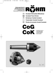
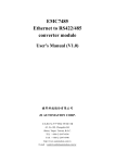
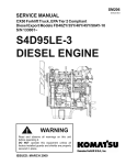
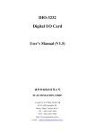
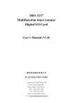
LDV-3 Low Voltage Unipolar Step Motor Driver USER’S MANUAL (V1.2) 健昇科技股份有限公司 JS AUTOMATION CORP. 台北縣汐止市中興路 100 號 6 樓 6F,No.100,Chungshin Rd. Shitsu, Taipei, Taiwan, R.O.C. TEL:886-2-2647-6936 FAX:886-2-2647-6940 http://www.automation.com.tw E-mail:[email protected] CONTENTS 1. SPECIFICATIONS............................................................................................. 2 2. LAYOUT.............................................................................................................. 2 3. JUMPER .............................................................................................................. 3 4. CURRENT ADJUST .......................................................................................... 4 5. INDICATORS ..................................................................................................... 4 6. TERMINALS ...................................................................................................... 4 1 Thank you for your purchasing LDV-3 low voltage unipolar step motor driver. The specifications and function descriptions are as follows: 1. Specifications 1.1 Max output:1.5A per phase, recommand to use any unipolar step motor with phase current less than 1.5A. 1.2 Auto power down: standby more than 2sec, auto power down to 60% of rated current 1.3 Current off: controlled by external terminal input to release motor. 2. Layout 2 3. JUMPER JUMPER function JUMPER JP1 JP2 JP3 SHORT OPEN 1 Pulse Mode HALF STEP FULL POWER Dual Pulse Mode FULL STEP HALF POWER Note:The motor maybe overheat while setting driver at full power mode. If the application need full holding torque at stand still, it is recommend to use a fan to ventilation. Function description 1. 1 Pulse Mode: 2. to control the motor rotation by clock input and the direction by direction Note: CW+,CW_ terminal used as CLOCK input in “1 pulse mode” CCW+,CCW- terminal used as DIRECTION input in “1 pulse mode” Dual Pulse Mode: 3. to control the motor clockwise rotation by CW+,CW- and counter clockwiserotation by CCW+,CCWHALF STEP: 4. to step the half rated step angle Note: 4 phase step motor rated step angle is 1.8 degree, and half step is 0.9 degree, this means 400 step per revolution at half step mode. FULL STEP: 5. to step the rated step angle FULL POWER: 6. driver supplies the step motor at adjust current in spite of runing or stand still. HALF POWER: driver supplies the step motor at adjust current in runing and half power at stand still. 3 4. Current Adjust Cw direction adjust to increase step motor current, max up to driver rated current. ccw direction adjust to decrease step motor current. Note: If you want to measure the exact current flow in the step motor, please connect the motor with the driver as follows and set driver at full power mode full step mode no pulse input (just power on ) 5. Indicators PL:power ZERO:active phase return to original state (every 4 step in full step mode or 8 steps in half step mode) CO:LED lights while motor in current off state 6. Terminals 6.1 CW+,CW-/(CLOCK+,CLOCK-): dual pulse mode: clockwise pulse input 1 pulse mode: rotation pulse input 6.2 CCW+,CCW-/(DIR+,DIR-): dual pulse mode: counter clockwise pulse input 1 pulse mode: rotation rirection input 6.3 CO+,CO-: step motor current command input 6.4 +24V:power supply input rated 24V 6.5 GND:ground of +24V 6.6 A:syep motor A phase coil 6.7 B:syep motor B phase coil 6.8 A:syep motor /A phase coil 6.9 B:syep motor /B phase coil 6.10 COM:step motor common node Note: 1. Do not make any connection change while power on. 2. Please refer to motor data sheet to confirm the phase. 4