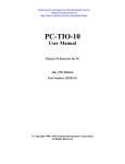
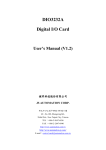
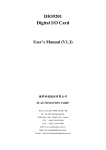
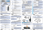
1
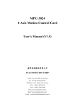
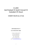
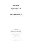
ENC-9266
Encoder/Linear Scale
Interface Card
User's Manual (V2.2)
健昇科技股份有限公司
JS AUTOMATION CORP.
台北縣汐止市中興路 100 號 6 樓
6F,No.100,Chungshin Rd.
Shitsu, Taipei, Taiwan, R.O.C.
TEL:886-2-2647-6936
FAX:886-2-2647-6940
http://www.automation.com.tw
E-mail:[email protected]
Correction record
Version
Record
1
Contents
1.
2.
3.
4.
5.
6.
7.
8.
9.
10.
11.
12.
13.
14.
Forward................................................................................................................................................4
Features................................................................................................................................................5
2.1 ENC-9266 Main card.................................................................................................................5
Specifications.......................................................................................................................................6
3.1 ENC-9266 Main card.................................................................................................................6
3.2 ADP-9266DIN Din rail mounted wiring board ......................................................................7
Layout and dimensions ........................................................................................................................8
4.1 ENC-9266 Main card layout .....................................................................................................8
4.2 ENC-9266 Main card dimension...............................................................................................8
4.3 ADP-9266DIN Din rail mounted wiring board layout ...........................................................9
4.4 ADP-9266DIN Din rail mounted wiring board dimension ....................................................9
CN1 Pin definitions ...........................................................................................................................10
5.1 CN1 Front view of connector ..................................................................................................10
I/O Interface diagram.........................................................................................................................11
6.1 Input diagram...........................................................................................................................11
External wiring diagram ....................................................................................................................12
Hardware settings ..............................................................................................................................13
8.1 Setting of counter clear condition.............................................................................................13
8.2 Polarity setting of home L/S and zero phase input...................................................................13
8.3 CARD Address setting .............................................................................................................14
Operations..........................................................................................................................................15
9.1 CARD Address setting (SW2) .................................................................................................15
Applications .......................................................................................................................................16
Programming examples (DEMO.).....................................................................................................17
11.1 “C” Language availed..............................................................................................................17
Ordering information .........................................................................................................................18
Functions of registers.........................................................................................................................19
13.1 Chip programming...................................................................................................................19
13.2 Special function of Z axis ........................................................................................................23
13.3 Status of zero phase and home.................................................................................................23
Functional diagram ............................................................................................................................24
2
Notes on hardware installation
Please follow step by step as you are installing the control cards.
1. Be sure your system is power off.
2. Be sure your external power supply for the wiring board is power off.
3. Plug your control card in slot, and make sure the golden fingers are put in right contacts.
4. Fasten the screw to fix the card.
5. Connect the cable between the card and wiring board.
6. Connect the external power supply for the wiring board.
7. Recheck everything is OK before system power on.
8. External power on.
Congratulation! You have it.
For more detail of step by step installation guide, please refer the file “installation.pdf “ on the CD
come with the product or register as a member of our user’s club at:
http://automation.com.tw/
to download the complementary documents.
3
1. Forward
Thank you for your selection of our ENC-9266 encoder/linear scale interface card.
In the field of automation, encoder and linear scale as feedback or measuring element is
common used in the microprocessor control system. But for the versatile application in PC
based control, only a few selections you can make.
We integrate 3 axes (channels) in one card and provide photo coupler isolation and
experienced functions. Low cost and high performance makes this card a better choice.
Other encoder/linear scale interface card:
LSI-2104 4 axes quadrature encoder/linear scale counter card (ISA bus)
LSI-3104 4 axes quadrature encoder/linear scale counter card (PCI bus)
LSI-3123L low cost 3 axes quadrature encoder/linear scale counter card (no touch probe
trigger latch function) (PCI bus)
LSI-3123 3 axes quadrature encoder/linear scale counter card (PCI bus)
LSI-3123A 3 axes quadrature encoder/linear scale counter card with fast coordinate rebuild
function (PCI bus)
LSI-3134 4 axes quadrature encoder/linear scale counter card with FIFO compare mode (PCI
bus)
LSI-3144 4 axes high performance encoder/linear scale counter card (PCI bus)
Any comment is welcome,
please visit our website: www.automation.com.tw for the up to date information.
4
2. Features
2.1 ENC-9266 Main card
Common to X,Y,Z channel
2.1.1 High noise immunity with photo-coupler isolation。
2.1.2 High speed of receiving pulse up to 1M pps。
2.1.3 Programmable Z (channel) counter as standard calendar clock。
2.1.4 Built-in DC-DC converter for encoder/linear scale。
2.1.5 Programmable counter in binary or decimal mode。
2.1.6 Input signal involved A, B, Z and Home sensor per channel。
2.1.7 Dip switch selectable polarity for Z and Home sensor。
2.1.8 Dip switch selectable counter clear at coincidence of Z and Home sensor
2.1.9 Programmable multiply rate at X1, X2, X4
2.1.10 Programmable single or dual pulse input mode
Special function for Z channel
2.1.11 Software programmable calendar clock (time base : 14.318MHZ)。
5
3. Specifications
3.1 ENC-9266 Main card
3.1.1
Input photo ─ coupler isolation voltage ─2500Vac 1min
3.1.2
Insulation resistance─100M Ohm(min) at 1000 Vdc
3.1.3
Data width ─ 8 Bits
3.1.4
I/O address length ─ 10 Bits per location selectable on Dip switch
3.1.5
Per I/O addressing ─ 6 locations
3.1.6
Base address with range ─ 100H to 3FFH increment by 8
3.1.7
Channels ─ X, Y, Z total 3 Channels
3.1.8
Pulse Rate ─ 0 ~ 1 M pps
3.1.9
Input pulse multiply rate ─ X1, X2, X4 programmable (quadrature signal only)
3.1.10 Counting Mode ─ Up/Down at Binary Or decimal
3.1.11 Input Mode ─ (CLOCK/DIRECTION),(UP CLOCK/DOWN CLOCK),
(QUADRATURE)
3.1.12 Counting Length ─ 3 Bytes
3.1.13 Connection ─ 25 Pins D-Type female connector
3.1.14 Per wiring board ─ 3 channels + 3 Home I/P
3.1.15 External Power Supply ─ 12V DC – 24V DC
3.1.16 Operation temperature ─ 0 to 70° C
3.1.17 Operation humidity ─ RH5~95%, non-condensing
3.1.18 Dimensions ─ 174mm*108mm , 6.85(W)*4.25(H)in
6
3.2 ADP-9266DIN
Din rail mounted wiring board
3.2.1
External Supply : DC 12V ~ 24V
3.2.2
Differential to single-end conversion for ENC-9266
3.2.3
Specific Input : 3-Axis A+, A-,B+,B-,C+,C-
3.2.4
Connector : One D-type 25-pin male connector
3.2.5
Operation Temperature : 0 to +70 degree C
3.2.6
Operation Humidity : RH5~95%, non-condensing
3.2.7
Dimension : 86(W) * 113(L)* 45(H)mm , 3.39(W)*4.45(L)*1.77(H)in
7
4. Layout and dimensions
4.1 ENC-9266 Main card layout
ON
ON
0
1
0
1
2
X-CLR
3
4
Z-CLR
Y-CLR
5
6
X-HOME
X-ZERO
7
8
1
1
2
3
ZHOME
A9
A8
4
5
6
7
8
A6
A5
A4
A3
Y-HOME
Y-ZERO
Z-ZERO
A7
Polarity setting DIP SW1
I/O Address setting DIP SW2
4.2 ENC-9266 Main card dimension
8
4.3 ADP-9266DIN
Din rail mounted wiring board layout
4.4 ADP-9266DIN
Din rail mounted wiring board dimension
9
5. CN1 Pin definitions
5.1 CN1 Front view of connector
1:X_A PHASE
2:X_B PHASE
3:X_C PHASE
4:X_HOME
5:Y_A PHASE
6:Y_B PHASE
7:Y_C PHASE
8:Y_HOME
9:Z_A PHASE
10:Z_B PHASE
11:Z_C PHASE
12:Z_HOME
13:NC
1
14
2
15
3
16
4
17
5
18
6
19
7
20
8
21
9
22
10
23
11
24
12
25
13
14:External power input (+12V~+24V)
15:External power input (+12V~+24V)
16:External power input (+12V~+24V)
17:External power input -GND
18:External power input -GND
19:External power input -GND
20:Regulated output (+5V)
21:Regulated output (+5V)
22:Regulated output (+5V)
23:Regulated outpu-GND
24:Regulated outpu-GND
25:Regulated outpu-GND
Notes:
In normal counter mode application:
A-PHASE input maybe programmed as CLOCK(for single phase clock mode) or UP
COUNT(for dual phase clock mode)。
B-PHASE input maybe programmed as DIRECTION (for single phase clock mode) or DOWN
COUNT(for dual phase clock mode)。
10
6. I/O Interface diagram
6.1 Input diagram
CARD
+5V
+24Ve
5V Regulator
External Supply
330
1
4
0V
2
3
1K
1N4148
EXT_IN
0V
11
7. External wiring diagram
12
8. Hardware settings
8.1 Setting of counter clear condition
If you wish to clear counter during home L/S and zero phase are both active, you should
set the corresponding bit of that axis to "on" position to activate the function. The
definition of each bit is as follows:
SW1:
BIT1
X-CLR
BIT2
Y-CLR
BIT3
Z-CLR
8.2 Polarity setting of home L/S and zero phase input
Both polarity of home L/S and zero phase input from encoder/linear scale are different from each
other of manufactures. This card provides polarity to adjust for different type devices. Any bit set "on"
means the polarity is "active low" , and else is "active high". The definition of each bit is looked as
follows including portion of Dip SW1 & Dip SW2.
SW1:
BIT4
BIT5
BIT6
BIT7
BIT8
X-ZERO X-HOME Y-ZERO Y-HOME Z-ZERO
SW2:
BIT1
Z-HOME
DIP SW1(Example of polarity optional setting):
ON
0
1
1
2
3
4
5
6
7
8
X-CLR
Z-CLR
X-HOME Y-HOME
Y-CLR
X-ZERO Y-ZERO Z-ZERO
13
8.3 CARD Address setting
Dip switch SW2 is used for base address setting, a ENC-9266 card occupied 8
consecutive I/O locations. The address and switch bit mapping is as follows, any bit sets "on"
means the corresponding address bit "0". For example of base address 280H needs to set as the
diagram shown.
Note: Bit1 is used as polarity setting of ZHOME. Combined as portion of Dip SW1.
SW2:
BIT1
ZHOME
BIT2
A9
1
BIT3
A8
0
BIT4
A7
1
BIT5
A6
0
DIP SW2(Example of address optional setting):
ON
0
1
1
2
3
4
5
6
7
8
ZHOME A9
A8
A7 A6
A5
A4
A3
14
BIT6
A5
0
BIT7
A4
0
BIT8
A3
0
9. Operations
9.1 CARD Address setting (SW2)
I/O BASE ADDRESS
Read
Write
Base address +0
Read data from X channel
Write data to X channel
Base address +1
Read control register of X channel Write control register of X channel
Base address +2
Read data from Y channel
Base address +3
Read control register of Y channel Write control register of Y channel
Base address +4
Read data from Z channel
Write data to Z channel
Base address +5
Read control register of Z channel
Write control register of Z channel
Base address +6
undefine
Enable Z channel special function
Base address +7
Read Home and Zero phase status
undefine
Write data to Y channel
※Note:ENC-9266card occupied consecutive eight of I/O locations and do not conflict with others
15
10. Applications
For counting pulses on the fly, such as:
-- Encoder on servo/vector motor
-- Encoder on hybrid/ micro-stepping motor
-- Encoder on DC/AC motor
-- Optical scale
-- Magnetic linear scale
-- Timing disk/sprocket
Pulse signal receiver/display
16
11. Programming examples (DEMO.)
11.1 “C” Language availed
//
short source prog. of ENC-DEMO.C
#include <dos.h>
#include <conio.h>
#include <ctype.h>
#include <stdio.h>
//
void main()
// begin
{
unsigned long counter_data;
//reading counter value, store to memory location.
clrscr(); // clear screen
printf("Please set ENC-9266 base address to 280H \n");
// initial set
MCR =20H,store initial set value to “MCR” counter
outportb(0x281,0x20);
outportb(0x281,0x48);
// initial set
ICR =48H,set phase A,B, input
outportb(0x281,0x90);
// initial set
OCR =90H,set binary mode
outportb(0x281,0xFF);
// initial set
QR =FFH,set quadrant resolution of per phase signal
printf("Press any key to preset counter value \n");
printf("set counter = 6476936 \n");
getch();
// waiting keyboard input, then load to counter as pre-setting value
outportb(0x281,0x01);
// pre-store address index to PR/OL
outportb(0x280,0x88);
// write lower portion of bytes
6476936 D=62D488 H
outportb(0x280,0xD4); // write middle portion of bytes
outportb(0x280,0x62);
// write high portion of bytes
// load to counter form pre-setting of counter.
outportb(0x281,0x08);
// reading keyboard input then display on screen
clrscr();
printf("X-CNTR
: 00000000 \n");
printf("Press any key to stop program!");
_setcursortype(_NOCURSOR);
while (!kbhit() )
// continuous reading value in counter while keyboard still inactive
{
outportb(0x281,0x03);
// write to MCR 03H,pre-store address index to PR/OL
counter_data=inportb(0x280)+inportb(0x280) * 256L+inportb(0x280) * 65536L;
// read value in counter, store to counter_data, read 3 bytes, then shift to do “ADD”
gotoxy(14,1);cprintf("%08lu",counter_data);// print on screen
}
}
// end
17
12. Ordering information
PRODUCT
ENC-9266
ADP-9266DIN
M270325X4
M270325X4S
M270325X0
M270325X0S
DESCRIPTIONS
3-axis Quadrature Encoder Counter Card
DIN rail mounted wiring board for ENC-9266, differential to single-end
D type 25p male-female cable 1.5M
D type 25p male-female cable 1.5M, shielding
D type 25p male-female cable 3.0M
D type 25p male-female cable 3.0M, shielding
18
13. Functions of registers
13.1 Chip programming
Each channel is implement with one specific designed chip, which occupies 2 I/O addresses.
Inside the chip there are several registers to control its functions:
MCR :master control register
ICR :input control register
OCR :output control register
QR :quadrature control register
SR :status register
PR :counter preset buffer (3 BYTES)
OL :counter output latched buffer (3 BYTES)
CY :CARRY
CYT :CARRY TOGGLE
BW :BORROW
BWT :BORROW TOGGLE
EQ :EQUAL
EQT :EQUAL TOGGLE
Since each channel has the same chip, we take X axis as example. (ref. Function block
diagram)
I/O address
I/O BASE ADDRESS+0
I/O BASE ADDRESS+1
R/W
Status
READ
Read OL
WRITE
Write PR
READ
Read SR
WRITE
(Write to control registers)
MCR (DATA MUST BE 00XXXXXX)
ICR
(DATA MUST BE 0100XXXX)
OCR (DATA MUST BE 10XXXXXX)
QR
19
(DATA MUST BE 111111XX)
※MCR,ICR,OCR,QR occupies same address
MCR:master control register, only the data format 00xxxxxx will accept.。
BIT7:must be 0
BIT6:must be 0
BIT5:1:MASTER RESET bit ,
set to "1" the CNTR,ICR,OCR,BWT,CYT,EQT and address pointer of PR/OL
will reset to "0". PR reset to "FFFFFF",and SIGN to "1".
BIT4:1:reset EQT (EQT=0)
BIT3:1:load CNTR from PR (24 BITS)
BIT2:1:reset CNTR,BWT,CYT (CNTR=0,BWT=0,CYT=0)
and SIGN (SIGN=1).
BIT1:1:load OL from CNTR (24 BITS)
BIT0:1:reset address pointer of PR/OL
ICR:input control register,only the data format 0100xxxx will accept.。
BIT7:must be 0
BIT6:must be 1
BIT5:must be 0
BIT4:must be 0
BIT3:1:ENABLE A/B input
0:DISABLE A/B input
BIT2:1:counter down count one pulse , i.e. CNTR-1 (if A/B input is ENABLED)
<P.S.: after set BIT2=1,if program encountered once, then “ICR”
buffer value decreased by 1.
0:null
BIT1:1:counter up count one pulse , i.e. CNTR+1 (if A/B input is ENABLED)
<P.S.: after set BIT1=1,if program encountered once, then “ICR”
buffer value increased by 1.
0:null
BIT0:1:1 - set A input as CLOCK input,B input as DIRECTION input.
While B=0 upcount,B=1 down count.。
20
OCR:output control register , only the data format 10xxxxxx will accept.。
BIT7:must be 1
BIT6:must be 0
BIT5,BIT4:don't care
BIT3:must be 0
BIT2:1:divide N mode(during CY or BW occurred CNTR will load from PR)
0:counting mode
BIT1:1:single counting mode
Load or reset CNTR begins counting,stopped while CY or BW occurred.
※Note: In this counting mode CY and BW has no output, but CYT and BWT is
available for checking end of count.
0:counting mode
BIT0:1:BCD counting mode
0:BINARY counting mode
※Note: If QR is set as quadrature mode,A/B input will become A PHASE and B
PHASE input.
0 - set A input as UP CLOCK input,B input as DOWN CLOCK inoput.
QR:quadrature control register,only the data format 111111xx will accept.。
BIT7:must be 1
BIT6:must be 1
BIT5:must be 1
BIT4:must be 1
BIT3:must be 1
BIT2:must be 1
BIT1,BIT0:
00:non quadrature counting mode
01:quadrature counting mode and multiply X 1
10:quadrature counting mode and multiply X 2
11:quadrature counting mode and multiply X 4
21
SR:status register,data read in the format 111xxxxx。
BIT7:returns 1
BIT6:returns 1
BIT5:returns 1
BIT4:(UP/DOWN)
1:currently up count (returns 1 in non quadrature mode)
0:currently down count
BIT3:(SIGN)
1:CNTR(OVERFLOW)
0:CNTR(UNDERFLOW)
BIT2:EQT
BIT1:CYT
BIT0:BWT
,toggles while CNTR=PR
,toggles while CARRY occurs
,toggles while BORROW occurs
PR:counter preset buffer, 3 byte long
Programming sequence as follows:
1. Write 00XX0X01 to MCR
;RESET PR/OL ADDRESS POINTER
2. Write to PR
;LOAD LSB INTO PR
;AND INCREMENT ADDRESS POINTER
3. Write to PR
;LOAD MIDDLE BYTE INTO PR
;AND INCREMENT ADDRESS POINTER
4. Write to PR
;LOAD MSB INTO PR
;AND INCREMENT ADDRESS POINTER
If you want to load CNTR from PR
;TRANSFER PR TO CNTR
5. Write 00001000 to MCR
OL:counter output latched buffer (3 BYTES)
Programming sequence as follows:
1. Write 00000011 to MCR ;RESET PR/OL ADDRESS POINTER
;AND TRANSFER CNTR TO OL
2. Read OL
;READ LSB OF OL
;AND INCREMENT ADDRESS POINTER
3. Read OL
;READ MIDDLE BYTE OF OL
;AND INCREMENT ADDRESS POINTER
4. Read OL
;READ MSB OF OL
;AND INCREMENT ADDRESS POINTER
22
13.2 Special function of Z axis
After power on , the Z counter of Z axis should be programmed as counter or timer.
If timer function (based on 14.318 MHZ) is required, the programming sequence is as
follows:
1. Before power on disconnect the Z axis input. ( No need any input in this mode)
2. Write XXXXXXX1 to BASE ADDRESS + 6 to enable 14.318 MHZ time base clock.
3. Other functions may program as previous sections.
If we take Z axis counter as general count (like X,Y axes)
1. Before power on connect the Z axis input.
2. Write XXXXXXX to BASE ADDRESS + 6 to switch input to external terminals.
3. Other functions may program as previous sections.
13.3 Status of zero phase and home
Status can be read from BASE ADDRESS+7
BIT7:undefined
BIT6:undefined
BIT5:Zero phase status of Z axis
BIT4:Home status of Z axis
BIT3:Zero phase status of Y axis
BIT2:Home status of Y axis
BIT1:Zero phase status of X axis
BIT0:Home status of X axis
23
14. Functional diagram
24