Transcript
Position Indicator User Manual
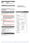
1. Model
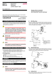
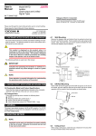
6. Wiring Diagram
SCH-2402-3
2.Product
Position Indicator
+
DC 24V
3. General
L
(A) Feature:Using the LED to light up the information on the display's surface.
Negative Trigger
-
0V
(B) Installed location:On the Hall.
J1.J2
(C) Function:Informed the passenger who are waiting for the elevators on the
hall by the lights when the elevators arrive.
DC 24V
POWER SUPPLY
PTH-2410-P
7. Dimension Diagram
4. Installation
(A)Fix the unit on the place which the lantern is normally installed.
(B) Follow the wiring diagram to connect the wires.
(C) Check the short circuit between the wires by the multi-m
41 40.6
(D)Turn oh the DC24V power and send the signal,the unit should work
correctly as the setting.
(E) The installation has been completed after above procedure.
5. Specification
Display color
Dimension(L*W*H)
Weight
Red、Green、White LED
830*170*84.6mm
6.2kg
32
153 mA(Red)
185 mA(Red)
198 mA(Red)
170
Standard input voltge 150 mA(Green) 131 mA(White)
Low input voltage
126 mA(Green) 53 mA(White)
High input voltage
158 mA(Green) 150 mA(White)
106
Standby Consumption
current
DC 24V
DC 16V~DC 30V
0mA
32
Standard Voltage
Voltage Range
Standby consumption power
21.75
71.5
643.5=P 71.5*9
71.5
21.75
3
830
Unit:mm