1
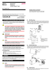
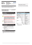
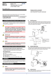
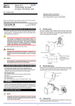
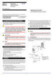
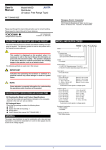
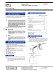
User’s
Manual
Model VJHR
Isolator
(Reverse Output Type)
(Isolated Single-output and
IM 77J01H12-01E Isolated Dual-output Types)
Network Solutions Business Divisiion
2-9-32, Naka-cho Musashino-shi, Tokyo 180-8750 Japan
Phone: +81-422-52-7179 Facsimile: +81-422-52-6793
Please read through this User’s Manual before use for correct handling.
Please keep this User’s Manual for future reference.
IM 77J01H12-01E
1st Edition Jul. 2003 (MC)
2nd Edition June 2004 (YK)
1. CAUTIONARY NOTES FOR SAFE USE OF THE PRODUCT
This User’s Manual should be carefully read before installing and operating the product. The following symbol is used on the product and in
this manual to ensure safe use.
4.1
Wall Mounting
Loosen the main unit-fixing screw of the product and pull out the main
unit from the socket. Fix the socket on the wall with screws. Next, insert the main unit into the socket and fasten the main unit with the main
unit-fixing screw.
Mounting
screws
This symbol is displayed on the product when it is
necessary to refer to the User’s Manual for information on
personnel and instrument safety. This symbol is displayed
in the User’s Manual to indicate precautions for avoiding
danger to the operator, such as an electric shock.
Main unit
Output-1
Zero-adjustment volume
Span-adjustment volume
Output-2
Zero-adjustment volume
Span-adjustment volume
The following symbols are used only in this manual.
IMPORTANT
<Mounting Dimensions>
Indicates that operating the hardware or software in a
particular manner may cause damage or result in a system
failure.
Check that the model and specifications indicated on the nameplate
attached to the side face of the main unit are as ordered.
Main
unit-fixing
screw
Unit: mm
59±0.3
Draws attention to essential information for understanding
the operations and/or functions of the product.
(1) Checking the Model and Product Specifications
Threaded hole for
fixing the main unit
29.5 or more
2-M4 or 2-ø4.5 or more
22±0.2
NOTE
2. CHECKING PRODUCT SPECIFICATIONS AND PACKAGED ITEMS
Socket
4.2
DIN Rail Mounting
Insert a DIN rail into the upper part of the DIN rail groove on the rear of
the socket, and then slide the slide lock at the lower part of the socket
upwards until the socket is fixed into position as shown below.
Fit into here
(2) Packaged Items
Check that the packing carton contains the following items:
● VJHR: 1
● Tag number label: 1 sheet
● Shunt resistor (for current input): 1
● User’s Manual (this manual: IM 77J01H12-01E): 1 copy
DIN rail
DIN rail
Push
(Rear of the socket)
3. GENERAL
This plug-in type isolator converts DC current or DC voltage signals into
isolated, and inverted DC current or DC voltage signals.
4. MOUNTING METHOD
DIN rail
Slide lock
NOTE
Insert/pull out the main unit into/from the socket vertically
to the face of socket. Otherwise the terminals are bent and
it may cause a bad contact.
4.3
Mounting Using a Multi-mounting Base
When using a multi-mounting base, see the User’s Manual for VJCE
(VJCE Mounting Base).
4.4
Using a Duct
When using a wiring duct, install the duct at leaset 30 mm away from
the top and bottom faces of the main unit.
5. INSTALLATION LOCATIONS
7. MAINTENANCE
● Avoid the following environments for installation locations:
Areas with vibration, corrosive gases, dust, water, oil, solvents, direct sunlight, radiation, a strong electric field, and/or a strong
magnetic field
● If there is any risk of a surge being induced into the power line
and/or signal lines due to lightning or other factors, a dedicated
lightning arrester should be used as protection for both this unit
and a field-installed device.
The product starts running immediately when the power is turned on;
however, it needs 10 to 15 minutes of warm-up before it meets the
specified performance.
7.1
7.2
6. EXTERNAL WIRING
To avoid the risk of an electric shock, turn off the power
supply and use a tester or similar device to ensure that no
power is supplied to a cable to be connected, before carring
out wiring work.
Wiring should be connected to the terminals on the socket of the product. The terminals for external connections are of M3 screws. Use
crimp-on terminal lugs for connections to the terminals.
● Recommended cables: A nominal cross-sectional area of 0.5 mm2
or thicker for signal cables, and that of 1.25 mm2 or thicker for
power cables.
External receiving resistor
(Shunt resistor)
for current input
Input
DC voltge/
current
standard
Input signal
+
Ri
–
3
6
2
1
5
Calibration Procedure
(1) Connect the instruments as shown below. First adjust the output-1
signal and then the output-2 signal.
(2) Use the DC voltage/current standard and apply input signals
equivalent to 0, 25, 50, 75, and 100% of the input span to the
product. Check to see the corresponding output voltages are 0,
25, 50, 75, and 100% respectively and within the specified accuracy rating. “R” is used for current output.
● If the output signals are out of the accuracy rating range, adjust
the output signal level using the zero and span adjustment volumes on front face of the product.
WARNING
External receiving resistor
(Shunt resistor)
for current input
Calibration Apparatus
● A DC voltage/current standard (Yokogawa 7651 or the equivalent)
● A digital multimater (Yokogawa 7561 or the equivalent)
● A precision resistor of 250 ± 0.01%, 1 W
3
1
Ri
3
6
Ri: External receiving resistor
for current input
(See chapter 6.)
3
2
Ro
5
9
2
5
Power Supply
11
N–
9
Output-1
Ro
–
Power supply
10
L
11
Digital
multimater
7
7
Output-1
7
L+
8
11 10
+
7
11 10
10
4
Ri: External receiving resistor for
current input (See the table below.)
4
8
1
5
Output-2
1
Output-2
9
2
8
N GND
9
Digital
multimater
Ro: 250 precision resistor
for current output
+
–
8
GND
<External Receiving Resistor (Shunt Resistor) for Current Input>
Input ragne Resistance Part No.
10 to 50 mA DC 100 E9786WD
4 to 20 mA DC
0 to 20 mA DC 250 E9786WE
0 to 16 mA DC
Input ragne Resistance Part No.
2 to 10 mA DC
500 E9786WF
0 to 10 mA DC
1 to 5 mA DC
1 k E9786WG
0 to 1 mA DC
IMPORTANT
● The power line and input/output signal lines should be
installed away from noise-generating sources. Other
wise accuracy cannot be guaranteed.
● The grounding resistance must be 100 Ω (JIS Class D
grounding). The length and thickness of the grounding
cable should be as short and thick as possible. Directly
connect the lead from the ground terminal (terminal no.
8) of the product to the ground. Do not carry out daisychained inter-ground terminal wiring.
● Use of the product ignoring the specifications may
cause overheating or damage. Before turning on the
power, ensure the following:
(a) Power supply voltage and input signal value applied
to the product should meet the required
specifications.
(b) The external wiring to the terminals and wiring to
ground are as specifications.
● Do not operate the product in the presence of
flammable or explosive gases or vapors. To do so is
highly dangerous.
● The product is sensitive to static electricity; exercise
care in operating it. Before you operate the product,
touch a nearby metal part to discharge static electricity.
2
IM 77J01H12-01E
2nd Edition June 01,2004-00