1
TM
DL
User Manual
DLTM
User Manual
Publication Number:
OM-20000035
Revision Level:
3
June 9, 2000
• MiLLennium, Narrow Correlator, NovAtel, ProPak, RT-2, RT-20 and SoftSurv are registered trademarks of NovAtel
Inc.
• DL, GPSAntenna and GPSCard are trademarks of NovAtel Inc.
• All other brand or product names are trademarks or registered trademarks of their respective holders.
Proprietary Notice
Information in this document is subject to change without notice and does not represent a commitment on the part of
NovAtel Inc. The software described in this document is furnished under a license agreement or non-disclosure
agreement. The software may be used or copied only in accordance with the terms of the agreement. It is against the law
to copy the software on any medium except as specifically allowed in the license or non-disclosure agreement.
No part of this manual may be reproduced or transmitted in any form or by any means, electronic or mechanical,
including photocopying and recording, for any purpose without the express written permission of a duly authorized
representative of NovAtel Inc.
The information contained within this manual is believed to be true and correct at the time of publication.
© Copyright 2000 NovAtel Inc. All rights reserved
Unpublished rights reserved under International copyright laws.
Printed in Canada on recycled paper. Recyclable.
2
DL™ User Manual Rev 3
Table of Contents
TABLE OF CONTENTS
WARRANTY POLICY
7
CUSTOMER SERVICE
8
NOTICE
9
FCC Notice.................................................................................................................................................................9
CE Notice ...................................................................................................................................................................9
CAUTION! ................................................................................................................................................................9
FOREWORD
10
What’s New in this Edition ......................................................................................................................................10
1 - OVERVIEW
11
Models & Features ...................................................................................................................................................12
Operating Modes ......................................................................................................................................................13
Accessories and Options...........................................................................................................................................14
2 - SET UP
15
Setting Up at the Office............................................................................................................................................15
Setting Up in the Field..............................................................................................................................................16
Choose the Right Antenna........................................................................................................................................17
Connect Cables.........................................................................................................................................................19
I/O Port & Cables ............................................................................................................................................................19
Serial Ports & Cables .......................................................................................................................................................20
Peripheral Power Supply via COM2 Port ........................................................................................................................21
RF Port & Cables.............................................................................................................................................................21
Power Port & Cable .........................................................................................................................................................22
Using the Removable Flash Memory Card...............................................................................................................23
Sleep, Power Down and the Power Switch...............................................................................................................25
Status Indicators .......................................................................................................................................................26
3 - USING THE DL
27
System Behavior ......................................................................................................................................................27
Self-Test...........................................................................................................................................................................27
Autonomous Versus Host Controlled Operation ..............................................................................................................27
Default Schedule and Group Configuration .....................................................................................................................27
Site Records in Scheduled (Automatic) Logging Sessions...............................................................................................27
Monitoring Your System .................................................................................................................................................27
Communications with the DL...................................................................................................................................28
Data Logging............................................................................................................................................................28
Schedule Logging Operation............................................................................................................................................29
File Name Convention .....................................................................................................................................................29
Data Storage Requirements..............................................................................................................................................30
Errors ...............................................................................................................................................................................31
4 - FIRMWARE UPGRADES & UPDATES
32
Upgrade or Update the MiLLennium GPSCard .......................................................................................................32
Upgrading Using the $AUTH Command.........................................................................................................................32
Updating Using the “Loader” Utility ...............................................................................................................................33
Upgrade or Update the PDC Card ............................................................................................................................35
DL™ User Manual Rev 3
3
Table of Contents
APPENDICES
APPENDIX A - DL DRAWINGS
36
APPENDIX B - DL SPECIFICATIONS
37
APPENDIX C - PC CARD SPECIFICATIONS
40
APPENDIX D - PORT & CABLE PINOUTS
41
APPENDIX E - DL COMMANDS
47
Battery ......................................................................................................................................................................48
Del ............................................................................................................................................................................48
Dir ............................................................................................................................................................................49
Dump........................................................................................................................................................................49
Group........................................................................................................................................................................50
Loggroup ..................................................................................................................................................................53
Mets..........................................................................................................................................................................54
PDC ..........................................................................................................................................................................55
Project ......................................................................................................................................................................56
PSN ..........................................................................................................................................................................57
Pversion....................................................................................................................................................................57
Rename.....................................................................................................................................................................57
Schedule ...................................................................................................................................................................57
Site............................................................................................................................................................................60
Sleep.........................................................................................................................................................................62
Status ........................................................................................................................................................................63
Vout..........................................................................................................................................................................63
Write.........................................................................................................................................................................63
APPENDIX F - DL LOGS
64
PDC Files .................................................................................................................................................................64
BATA/B ...................................................................................................................................................................65
DIRA/B ....................................................................................................................................................................66
GROUPA/B..............................................................................................................................................................66
GRPA/B ...................................................................................................................................................................69
HDRA/B...................................................................................................................................................................71
LPSTATUSA/B........................................................................................................................................................73
META/B...................................................................................................................................................................74
MSGA/B...................................................................................................................................................................75
PDCVERA/B............................................................................................................................................................77
PROJECTA/B ..........................................................................................................................................................78
PSNA/B....................................................................................................................................................................79
SCHA/B ...................................................................................................................................................................80
SITELOGA/B...........................................................................................................................................................81
STATUSA/B ............................................................................................................................................................83
4
DL™ User Manual Rev 3
Table of Contents
APPENDIX G - CONVERSIONS
86
APPENDIX H - REPLACEMENT PARTS
87
APPENDIX I - OPTIONAL MOUNTING BRACKET
88
APPENDIX J - COMMAND PROMPT INTERFACE
90
TABLES
1: Positioning Modes of Operation.....................................................................................................................................12
2: Feature Summary - DL Models......................................................................................................................................13
3: Allowable Antenna Types..............................................................................................................................................17
4: Status Indicators - Meaning ...........................................................................................................................................26
5: Auto-Generated File Name Convention.........................................................................................................................30
6: Storage Requirements per Data Record .........................................................................................................................30
7: Memory Consumption – Typical Case for RTK Survey (2 Second Rate)......................................................................31
8: Memory Consumption – Typical Case for Static Survey (15 Second Rate)...................................................................31
9: Power Connector Pin Assignment..................................................................................................................................41
10: COM2 Serial Port - Connector Pin Assignment...........................................................................................................42
11: COM1 Serial Port - Connector Pin Assignment...........................................................................................................42
12: Straight Serial Cable - Pin Assignment ........................................................................................................................43
13: Null-Modem Cable - Pin Assignment ..........................................................................................................................44
14: I/O Connector Pin Assignment.....................................................................................................................................45
15: I/O Cable – Pin Assignment.........................................................................................................................................46
16: Weekday Abbreviations ...............................................................................................................................................57
17: Group Status Word Encoding.......................................................................................................................................67
18: Log Status Word Encoding ..........................................................................................................................................68
19: MSGA Error Code Definition ......................................................................................................................................76
20: Flag Word Encoding ....................................................................................................................................................81
21: PDC Status Word Encoding .........................................................................................................................................84
22: GPS Status Word Encoding .........................................................................................................................................85
DL™ User Manual Rev 3
5
Table of Contents
FIGURES
1: NovAtel DL – Front & Rear ..........................................................................................................................................11
2: Typical DL Configuration – Office................................................................................................................................15
3: Typical DL Configuration – Field..................................................................................................................................16
4: Close-up of Ports on Rear End-cap ................................................................................................................................19
5: Removing a Connector...................................................................................................................................................19
6: Opening the Cover .........................................................................................................................................................24
7: Handling the PC Card ....................................................................................................................................................24
8: Status Indicators .............................................................................................................................................................26
9: LOADER Options..........................................................................................................................................................34
10: Views
...................................................................................................................................................................36
11: Power Cables................................................................................................................................................................41
12: Straight Serial Cable - Illustration................................................................................................................................43
13: Null-Modem Serial Cable - Illustration........................................................................................................................44
14: I/O Cable - Illustration .................................................................................................................................................45
15: Mounting Bracket.........................................................................................................................................................88
16: Mounting Bracket Drill Holes – Dimensions ...............................................................................................................89
6
DL™ User Manual Rev 3
Warranty Policy
WARRANTY POLICY
NovAtel Inc. warrants that its Global Positioning System (GPS) products are free from defects in materials and
workmanship, subject to the conditions set forth below, for the following periods of time:
DL Series
GPSAntenna Series
Cables and Accessories
Software Support
One (1) Year
One (1) Year
Ninety (90) Days
One (1) Year
Date of sale shall mean the date of the invoice to the original customer for the product. NovAtel’s responsibility
respecting this warranty is limited solely to product repair at an authorized NovAtel location only. Determination of
repair will be made by NovAtel personnel or by technical personnel expressly authorized by NovAtel for this purpose.
THE FOREGOING WARRANTIES DO NOT EXTEND TO (I) NONCONFORMITIES, DEFECTS OR ERRORS IN
THE PRODUCTS DUE TO ACCIDENT, ABUSE, MISUSE OR NEGLIGENT USE OF THE PRODUCTS OR USE IN
OTHER THAN A NORMAL AND CUSTOMARY MANNER, ENVIRONMENTAL CONDITIONS NOT
CONFORMING TO NOVATEL’S SPECIFICATIONS, OR FAILURE TO FOLLOW PRESCRIBED INSTALLATION,
OPERATING AND MAINTENANCE PROCEDURES, (II) DEFECTS, ERRORS OR NONCONFORMITIES IN THE
PRODUCTS DUE TO MODIFICATIONS, ALTERATIONS, ADDITIONS OR CHANGES NOT MADE IN
ACCORDANCE WITH NOVATEL’S SPECIFICATIONS OR AUTHORIZED BY NOVATEL, (III) NORMAL WEAR
AND TEAR, (IV) DAMAGE CAUSED BY FORCE OF NATURE OR ACT OF ANY THIRD PERSON, (V) SHIPPING
DAMAGE; OR (VI) SERVICE OR REPAIR OF PRODUCT BY THE DEALER WITHOUT PRIOR WRITTEN
CONSENT FROM NOVATEL.
IN ADDITION, THE FOREGOING WARRANTIES SHALL NOT APPLY TO PRODUCTS DESIGNATED BY
NOVATEL AS BETA SITE TEST SAMPLES, EXPERIMENTAL, DEVELOPMENTAL, PREPRODUCTION,
SAMPLE, INCOMPLETE OR OUT OF SPECIFICATION PRODUCTS OR TO RETURNED PRODUCTS IF THE
ORIGINAL IDENTIFICATION MARKS HAVE BEEN REMOVED OR ALTERED.
THE WARRANTIES AND REMEDIES ARE EXCLUSIVE AND ALL OTHER WARRANTIES, EXPRESS OR
IMPLIED, WRITTEN OR ORAL, INCLUDING THE IMPLIED WARRANTIES OF MERCHANTABILITY OR
FITNESS FOR ANY PARTICULAR PURPOSE ARE EXCLUDED.
NOVATEL SHALL NOT BE LIABLE FOR ANY LOSS, DAMAGE OR EXPENSE ARISING DIRECTLY OR
INDIRECTLY OUT OF THE PURCHASE, INSTALLATION, OPERATION, USE OR LICENSING OR PRODUCTS
OR SERVICES. IN NO EVENT SHALL NOVATEL BE LIABLE FOR SPECIAL, INDIRECT, INCIDENTAL OR
CONSEQUENTIAL DAMAGES OF ANY KIND OR NATURE DUE TO ANY CAUSE.
There are no user-serviceable parts in this device, and no maintenance is required. When the status code indicates that a
unit is faulty, replace with another unit and return the faulty unit to NovAtel Inc.
You must obtain a RETURN MATERIAL AUTHORIZATION (RMA) number by contacting Customer Service
in any of the ways described on the next page. This number is needed before shipping any product to NovAtel or
your Dealer.
Once you have obtained an RMA number, you will be advised of proper shipping procedures to return any defective
product. When returning any product to NovAtel, please return all original diskettes along with the defective product in
the original packaging to avoid electrostatic and/or shipping damage.
ANY ATTEMPT TO OPEN THE CASE WILL IMPAIR THE WATER-RESISTANT QUALITIES OF THE
ENCLOSURE, AND VOID THE WARRANTY.
DL™ User Manual Rev 3
7
Customer Service
CUSTOMER SERVICE
For customer support contact your local NovAtel dealer first. If the problem remains unresolved, contact NovAtel
directly by any of the following ways:
•
•
•
toll-free hotline: 1 800 NOVATEL (8:00 AM - 4:30 PM MST, Canada and U.S.A. only)
telephone: 1 403 295 4900 (8:00 AM - 4:30 PM MST)
fax: 1 403 295 4901
•
•
e-mail: [email protected]
web site: http://www.novatel.ca
•
regular mail:
NovAtel Inc.
Customer Service Dept.
1120 - 68 Avenue NE
Calgary, Alberta
Canada
T2E 8S5
If you require customer service, please provide the following information along with a detailed description of the problem
when you call or write:
Serial No._______________________________________ Model No. _________________________________________
Software Release No. _____________________________
Date Purchased:__________________________________
Purchased from: ____________________________________________________________________________________
User name: _____________________________________ Title: ______________________________________________
Company: _________________________________________________________________________________________
Address:___________________________________________________________________________________________
City:___________________________________________ Prov/State: _________________________________________
Zip/Postal Code: _________________________________ Country: ___________________________________________
Phone #:________________________________________ Fax #: _____________________________________________
E-mail:_________________________________________
Interface: Computer type: _______________________________________ Operating Shell: ______________________
Other interface used: _________________________________________________________________________________
Please provide a complete description of any problems you may be experiencing, or the nature of your inquiry (attach
additional sheets if needed):
__________________________________________________________________________________________________
__________________________________________________________________________________________________
__________________________________________________________________________________________________
__________________________________________________________________________________________________
__________________________________________________________________________________________________
8
DL™ User Manual Rev 3
Notices
NOTICE
FCC NOTICE
The United States Federal Communications Commission (in 47 CFR 15) has specified that the following notices be
brought to the attention of users of this product.
“This equipment has been tested and found to comply with the limits for a class A digital device, pursuant to Part 15 of
the FCC rules. These limits are designed to provide reasonable protection against harmful interference when the
equipment is operated in a commercial environment. This equipment generates, uses, and can radiate radio frequency
energy and, if not installed and used in accordance with the instruction manual, may cause harmful interference to radio
communications. Operation of this equipment in a residential area is likely to cause harmful interference in which case
the user will be required to correct the interference at his own risk.”
“Changes or modifications not expressly approved by the party responsible for compliance could void the user’s authority
to operate the equipment.”
IMPORTANT: In order to maintain compliance with the limits of a Class A digital device, it is required to use properly
shielded interface cables (such as Belden #9539 or equivalent) when using the serial data ports, and double-shielded
cables (such as Belden #9945 or equivalent) when using the I/O strobe port.
CE NOTICE
WARNING: This is a Class A product. In a domestic environment this product may cause radio interference in which
case the user may be required to take adequate measures.
CAUTION!
1.
This device incorporates circuitry to absorb most static discharges. However, severe static shock may cause
inaccurate operation of the unit. Use anti-static precautions where possible.
2.
This device is a precision instrument. Although it is designed for rugged operating conditions, it performs best when
handled with care.
3.
When the cover for the PC Card ATA mass storage card (PC Card) is closed and latched, the enclosure is sealed to
provide protection against adverse environmental conditions. To minimize the possibility of damage, always keep
this cover closed and latched except when exchanging PC Cards. Any attempt to remove this cover or the endcaps impairs the water-resistant qualities of the enclosure, and void the warranty.
4.
Do not eject the PC Card while the DL is logging data, as you may lose part of or your entire data file.
5.
The DL can accept an input supply voltage in the range +10.7 to +18 V DC. This may not be the same range as other
NovAtel products with which you are familiar. Operating the DL below 10.7 V DC causes the unit to suspend
operation. An input voltage above +18 V DC may physically damage the unit.
6.
The DL is not compatible with the ProPak series of power supplies and power cables.
7.
Drawing more than the specified maximum current (2 amps) from COM2 will cause an internal fuse to interrupt the
current. Restoring normal operation will require returning the unit to NovAtel.
DL™ User Manual Rev 3
9
Foreword
FOREWORD
Congratulations on your purchase of the DL, a GPS receiver with exceptional flexibility.
NovAtel is an industry leader in state-of-the-art GPS receiver design. We believe that our DL will meet your high
expectations, and are working hard to ensure that future products and enhancements will maintain that level of
satisfaction.
Scope
This manual provides sufficient information to allow you to set up and effectively use the DL. For any customer-service
problems or inquiries, please contact your dealer. If additional help is needed, contact Customer Service by any of the
means outlined on Page 8.
The following may provide you with additional valuable reference information:
• SoftSurv User Manual - a description of the SoftSurv suite of GPS surveying programs and utilities. SoftSurv and DL
are complementary products designed to work together. SoftSurv software provides a user-friendly graphical interface
to the DL, allowing you to focus on your work without needing to learn about the MiLLennium’s commands and logs.
SoftSurv contains all that you would typically need to interact with and configure the DL.
• MiLLennium GPSCard Command Descriptions Manual - a comprehensive description of every GPSCard command
and log available to you. You would only need to become familiar with this manual if you wished to interact with the
DL from the command-prompt interface, or in any other way chose not to use SoftSurv.
Throughout this document, metric SI (Système Internationale) units are used. Appendix G is included to assist you with
conversions to imperial units.
Wherever software commands are listed or described, certain conventions are followed. These are explained in the
section titled Syntax Conventions, Page 47.
WHAT’S NEW IN THIS EDITION
1.
Peripheral equipment power can now be provided through the receiver’s COM2 port. The output voltage is the same
as the connected active battery, with up to 2A of current available. This new definition of COM2 is fully compatible
with COM1, NovAtel cabling and other NovAtel ProPak receivers. Refer to the new VOUT command, Page 63 and
pinout description, Page 42.
2.
GPS receiver firmware has been enhanced to provide superior stand-alone base station operation.
3.
The DIR command, Page 49, has been modified to display previously supplied additional group information.
4.
There is a new WRITE command, Page 63, that allows data to be written to a specified data file on the PC Card.
5.
There is a new description of the PDC LOG command, Page 55, as well as a new PDC log, STATUSA/B, Page 83.
6.
A PROJECT command, Page 56, and a PROJECTA/B log, Page 78, has been added for project-related parameters.
7.
The GROUP command, Page 50, has been modified and a GROUPA/B log, Page 66, has been added to provide
support for additional group data.
10
DL™ User Manual Rev 3
1 – Overview
1 - OVERVIEW
The NovAtel DL is a high-performance GPS receiver. In applications when continuous user interaction is required, such
as in GIS surveying, a simple handheld controller, that does not require its own data logging memory, can be used with
DL. The reduced handheld data logger or controller requirements simplify your system and reduce its total cost and
power consumption. Depending on which model you purchase, it is capable of receiving and tracking the L1 C/A-code,
L1 and L2 carrier phase, and L2 P-code (or encrypted Y-code) of up to 12 GPS satellites. The DL can be used for either
single-point or differential applications. Patented Narrow Correlator tracking technology circuits combined with a
powerful 32-bit microprocessor make possible multipath-resistant processing at high data update rates. Excellent
acquisition and re-acquisition times allow this receiver to operate in environments where very high dynamics and
frequent interruption of signals can be expected. It features a rugged, reliable design for use in adverse environments.
The DL is engineered to provide years of reliable operation.
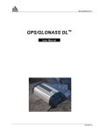
Figure 1 shows front (left photo) and rear (right photo) views of the DL.
Figure 1: NovAtel DL – Front & Rear
#
1
2
3
4
5
6
7
Description
PC Card access door
Power status indicator
Door latch
Position status indicator
Logging status indicator
Power switch
COM2 port indicator
#
Description
8
9
10
11
12
13
COM1 port indicator
I/O port
COM2/PWR serial/power port
COM1 serial port
Power port
Antenna connector
Once you connect the DL to an antenna and power supply, it begins operating as a fully functional GPS receiver (see
Chapter 2, Set Up, for more information on this topic). The DL is then ready for the most demanding applications – such
as survey, flight inspection, hydrographic survey and dredging, photogrammetry, agricultural applications, GIS and
differential reference station applications.
See CAUTION!, Page 9, for a list of items of which you should be aware as you set up and use the DL.
DL™ User Manual Rev 3
11
1 – Overview
MODELS & FEATURES
Table 1 lists the four available DL models available, each capable of multiple positioning modes of operation:
Table 1: Positioning Modes of Operation
Positioning Modes of Operation
DL Model
DL-L1
DL-RT20S
DL-L2
DL-RT2
Single point
√
√
√
√
Waypoint navigation
√
√
√
√
Pseudorange differential corrections (TX & RX)
√
√
√
√
Trimble CMR differential corrections (TX versions ≤ 3 & RX
version 3)
√
√
√
√
RTK pseudorange & carrier-phase double differencing: < 20
cm RMS accuracies (floating)
×
√
×
√
RTK pseudorange & carrier-phase double differencing: < 2
cm RMS accuracies (fixed)
×
×
×
√
Reverse-RTK
×
√
×
√
Each model has the following standard features:
• rugged shock, water, and dust-resistant enclosure
• NovAtel’s advanced MiLLennium L1/L2 GPS technology
• capability to log data to a removable Type II or Type III PC Card ATA mass storage card (PC Card) – eliminates
the need to purchase additional data logger peripheral equipment when continuous user interaction is not required
• capability to perform autonomous scheduled data collection, with the ability to go into low-power “sleep” mode
between scheduled data-collection sessions
• smart power sensing from two independent batteries, which permits automatic switchover
• two bi-directional serial ports, one of which has power, which support data transfer rates of up to 115,200
bit/second
• obsolescence prevention due to field-upgradeable firmware (program software). What makes one DL model
different from another is software, not hardware. This unique feature means that the firmware can be updated
anytime, anywhere, without any mechanical procedures whatsoever. For example, a DL model with L1-only
capabilities can be upgraded to a model with L1/L2 RT-2 in only a few minutes in your office; instead of in the
days or weeks that would be required if the receiver had to be sent to a service depot. All that is required to
unlock the additional features is a special authorization code. See Chapter 4 for further detail on this topic.
The DL features integrated memory (PC Card) for data logging, eliminating your need to purchase additional expensive
peripheral equipment
In addition, each model has unique features. These are summarized in Table 2 on the following page:
12
DL™ User Manual Rev 3
1 – Overview
Table 2: Feature Summary - DL Models
General
DL-L1
DL-RT20S
DL-L2
DL-RT2
L1 Channels (C/A code) & L2 Channels (P code)
12 & 0
12 & 0
12 & 12
12 & 12
Pseudorange measurements
√
√
√
√
Full-wavelength L2 carrier measurements
×
×
√
√
Ionospheric corrections in position calculations
√
√
√
√
2.5-bit sampling
√
√
√
√
Patented Narrow Correlator tracking technology
√
√
√
√
5 Input / Output strobe signals: mark input (position & time), 1PPS
timing output, measure output, programmable variable-frequency
output, solution status output
√
√
√
√
Fast re-acquisition
√
√
√
√
√
√
√
√
DL-L1
DL-RT20S
DL-L2
DL-RT2
NovAtel-proprietary ASCII and binary
√
√
√
√
NMEA Standard
√
√
√
√
RINEX Standard
√
√
√
√
RTCM Standard: Types 1,2,3,9,16,59N
√
√
√
√
Peripheral power supply output COM2
Output Data Log Formats
√
√
√
√
DL-L1
DL-RT20S
DL-L2
DL-RT2
Computed Data: Position, speed, direction, & clock offset
10
10 / 5
5
5
Measured Data (Observations): Pseudorange & carrier phase
20
20
10
10
Receiver Control
DL-L1
DL-RT20S
DL-L2
DL-RT2
Clock drift correction
√
√
√
√
Ability to save receiver configuration settings, & almanac
√
√
√
√
Reset (hardware or software activated)
√
√
√
√
Serial port control
√
√
√
√
Datum (table or user-definable)
√
√
√
√
Magnetic variation correction
√
√
√
√
Undulation (table or user-definable)
√
√
√
√
Position, height & velocity constraints
√
√
√
√
Satellite lockout, elevation cut-off and health control
√
√
√
√
RTCA Standard: Types 1,7
Data Logging Rates (per second)
OPERATING MODES
Whenever the DL is connected to a power source (regardless of whether the DL is turned “on” or “off”), it detects
whether there is a host computer connected to one of its serial ports. For example, this host computer could be a PC
running NovAtel SoftSurv Utilities software, or a data logger running suitable software. If a host computer is found, the
DL enters Manual mode and waits for a command; otherwise, the DL enters Automatic mode and operates according to
stored commands.
• Manual Operation: Among other things, a host computer can transmit scheduling and logging parameters,
receive collected data, and turn the DL on or off. In this mode, the DL does not need to be tracking satellites, or
even have an antenna connected to it.
• Automatic Operation: Once the DL receives configuration commands from a host computer, it operates
according to these parameters. Up to a week’s worth of data collection can be configured in advance.
DL™ User Manual Rev 3
13
1 – Overview
ACCESSORIES AND OPTIONS
The NovAtel DL can be used with the following accessories:
• SoftSurv software – a suite of programs that allows you to plan your data collection trip, configure your DL or
handheld data logger, post-process your collected data, and archive your information sets
• PC Card for data storage
• NovAtel GPSAntenna Model 501, 511, 521, or 531 – single frequency, active antennas designed for highaccuracy applications
• A choke ring is available for the 501 antenna (model A031) and the 531 antenna (model A032)
• NovAtel GPSAntenna Model 502, 503, or 512 - dual frequency, active antennas designed for high-accuracy
applications
• A choke ring is available for the 502 antenna (model A032) while the 503 antenna includes one
• NovAtel Model C005, C015, or C030 (5, 15 or 30 m length) coaxial antenna cable
• power cable to connect the DL to an automotive cigarette-lighter adapter
• battery
• bracket to allow the DL to be mounted to a surface or tripod
• 25-pin straight serial cable for compatibility with certain data communications devices
• power cable to connect the DL to one battery (33.5 cm or 75 cm lengths)
• power cable to connect the DL to two batteries (Y-cable)
Should you need to order an accessory or a replacement part, NovAtel part numbers are shown in Appendix H.
14
DL™ User Manual Rev 3
2 – Set Up
2 - SET UP
Setting up the DL is a straightforward process, whether you are in the field (collecting data) or back at the office
(configuring the DL, or transferring collected data to your PC for post-processing).
See CAUTION!, Page 9, for a list of items you should be aware of as you set up and use the DL.
SETTING UP AT THE OFFICE
Figure 2 displays how you might typically set up the DL at the office – for example, to load a schedule, or to transfer
collected data to a PC. In this situation, the PC is connected to the COM1 port, and energy is supplied by means of an
AC/DC converter that is connected to the Power port.
Figure 2: Typical DL Configuration – Office
For office work, a typical configuration would result from the following steps:
1.
2.
3.
4.
5.
Place the DL on a desk or other suitable work surface.
Connect an RS232C communication terminal (e.g. PC, data logger) to one of the serial ports of the DL. The supplied
null-modem cables are intended for RS232C communications only. See Serial Ports & Cables, Page 20.
Connect the output of a power source (e.g. AC/DC converter) to the input power port of the DL. Once power is
supplied, the DL turns on automatically and begins an initialization sequence. See Power Port & Cable, Page 22.
Press the power button or, if you are connected to the DL via a terminal, hit the <Enter> key and wait for a MSGA
log with a BOOTOK message to appear. If you are you are using SoftSurv to communicate with the DL, this initial
communication is handled by the software.
Communicate with the DL, transfer data to the PC (if you have inserted a PC Card containing previously recorded
data), or set up a data-collection schedule.
The sections of this chapter give further details on Steps #2 & #3, while Chapter 3 is devoted to Step #4.
DL™ User Manual Rev 3
15
2 – Set Up
SETTING UP IN THE FIELD
Figure 3 displays how you might typically use the DL in the field – for example, collecting data while receiving
differential information over a radio modem from a base station. In this situation, the GPS antenna is connected to the RF
port, the radio modem is connected to the COM1 port, and power is supplied by means of two batteries that are connected
to the Power port.
Figure 3: Typical DL Configuration – Field
For differential data collection in the field, a typical configuration is described below. This assumes that schedule and
logging parameters have already been loaded to the DL (see Chapter 3), and that a portable terminal is not being used. If
a portable terminal was being used, then at Step #7, when power was supplied, the DL would accept configuration
commands from the terminal.
1.
3.
Mount or place the DL on a secure, stable structure that will not sway or topple. For example, attach the DL to a
tripod leg using the optional mounting bracket (see Figure 14: Mounting Bracket and Figure 15, Appendix I).
Although the unit has a moisture and dust-resistant enclosure, shelter it from adverse environmental conditions when
possible.
Position the antenna at the desired location – e.g. on a tripod over a survey marker. The recommended antenna
depends on which model of the DL you purchased (see Choose the Right Antenna, Page 17). For maximum
positioning precision and accuracy, as well as to minimize the risk of damage, ensure that the antenna is securely
mounted on a stable structure that will not sway or topple. Where possible, select a location with a clear view of the
sky to the horizon so that each satellite above the horizon can be tracked without obstruction. The location should
also be one that minimizes the effect of multipath interference. For a discussion on multipath, please refer to the
appendix on Multipath Elimination Technology in the MiLLennium GPSCard Command Descriptions Manual.
Route and connect RF coaxial cable between the antenna and DL (see RF Port & Cables, Page 21).
16
DL™ User Manual Rev 3
2.
2 – Set Up
4.
The receiver provides battery power output (BAT) through COM2. It is possible to turn the supply On or Off using
the VOUT command, see Page 63. The BAT output is the switched output of the input power supply so that 12V
output requires 12V input.
5. RF Port & Cables (see RF Port &Cable, Page 21).
6. Connect an RS232C communication device to one of the serial ports of the DL (see Serial Ports & Cables, Page 20).
For example, this might be a radio modem, for receiving differential GPS messages from a base station. The
supplied null-modem cables are intended for RS232C communications only.
7. Insert a PC Card into the DL (see Using the Removable Flash Memory Card, Page 23).
8. Connect the output of a power source (e.g. battery) to the input power port of the DL (see Power Port & Cable, Page
22). Once power is supplied, the DL turns on automatically, begins an initialization sequence, and then enters lowpower mode. See also System Behavior, Page 27.
9. Exit low power mode by pressing the power button, or if connected via a terminal, by hitting the <Enter> key. If you
are going to configure the unit via DL commands, wait for a MSGA log with a BOOTOK message to appear first.
Otherwise, the DL will begin logging according to the stored configuration.
10. Monitor the status indicators (see Status Indicators, Page 26).
The sections of this chapter give further details on these steps.
CHOOSE THE RIGHT ANTENNA
The purpose of an antenna is to convert electromagnetic waves into electrical signals. An active antenna is required. It
has a Low Noise Amplifier (LNA) that boosts the strength of received signals to help offset the cable losses. The LNA
can be energized directly by the DL, or by another source. NovAtel recommends the use of active antennas only.
The recommended antenna depends on which model of the DL you purchased. Table 3 lists the allowable antenna types
for each of the DL models.
Table 3: Allowable Antenna Types
DL Model
Allowable Antenna
DL-L1
L1-only or L1/L2
DL-RT20S
L1-only or L1/L2
DL-L2
L1/L2
DL-RT2
L1/L2
GPS satellites transmit at two frequencies, 1227.60 MHz (L2) and 1575.42 MHz (L1). NovAtel offers a variety of
antenna models for GPS-only operation. All use low-profile microstrip technology and include band-pass filtering and an
LNA.
All active GPSAntennas can compensate for up to 13 dB of cable loss. Higher cable loss can be used but you should then
expect an increased degradation in signal strength.
The following are L1-only GPSAntennas:
• Model 501 - for use in surveying and other kinematic positioning applications; model A031 choke ring available
• Model 511 - for use in airborne, marine, ground vehicle or backpack applications
• Model 521 - for use in ground vehicle, backpack, or handheld applications
• Model 531 - for use in surveying and other kinematic positioning applications; water proof; model A032 choke ring
available
The following are L1/L2 GPSAntennas:
• Model 502 - for use in surveying and other kinematic positioning applications; model A032 choke ring available
DL™ User Manual Rev 3
17
2 – Set Up
•
•
Model 503 - for use with high-performance position-reference stations (features a built-in choke-ring ground plane
to minimize the effects of multipath interference)
Model 512 - for installation on aircraft (features aerodynamic styling)
Each of these models offers exceptional phase-center stability as well as a significant measure of immunity against
multipath interference. Each one has an environmentally sealed radome.
A choke ring’s unique construction substantially reduces the multipath effect on the GPS signal. The choke ring actually
reduces the antenna gain at low elevation, where the multipath is more prone to affect system accuracy. By reducing
measurement errors due to multipath, the result is greater accuracy in your positioning calculations.
WARNING: While there may be other antennas on the market that might also serve the purpose, please note that
the performance specifications of the DL are guaranteed only when it is used with a NovAtel model 531 (L1) or model
502 (L1/L2) GPSAntenna.
18
DL™ User Manual Rev 3
2 – Set Up
CONNECT CABLES
As shown in Figure 4, on the rear end-cap there are four labeled ports – I/O, COM2/PWR, COM1, and RF. There is also
an unlabelled power input port.
Figure 4: Close-up of Ports on Rear End-cap
Each connector is keyed to ensure that the cable can be inserted in only one way, to prevent damage to both the DL and
the cables. Furthermore, the connectors that are used to mate the cables to the DL have a locking mechanism that
requires careful insertion and removal. Observe the following when handling the cables.
• To insert a cable, make certain you are using the appropriate cable for the port – the serial cable has a different
connector (10 pin) than the I/O cable (8 pin).
• Line up the red dot on the connector shell with the red index mark on the receptacle on the DL.
• Insert the connector until it seats with a click; it is now locked in place.
• To remove a cable, grasp the connector by the knurled ring and pull (see Figure 5). DO NOT PULL DIRECTLY
ON THE CABLE.
Figure 5: Removing a Connector
I/O PORT & CABLES
DL incorporates an input/output (I/O) port, which allows access to the Mark input, Measure output, VARF output, 1PPS
output, and STATUS output signals. These are specialized signals that are used when the DL is part of an interconnected
DL™ User Manual Rev 3
19
2 – Set Up
system composed of devices that need to be synchronized with each other. For example, you could connect the DL to an
aerial camera in such a way that the DL recorded its position whenever the shutter button was pressed. This port is not
typically used for stand-alone applications. The five signals are described further in Table 14: I/O Connector Pin
Assignment, Page 45, as well as in the Input / Output Strobes section of Appendix B.
The I/O strobe lines can be accessed by inserting the 8-pin LEMO connector of the I/O strobe port cable into the I/O port.
Figure 13, Page 45, and Table 15: I/O Cable – Pin Assignment, Page 46 contains wiring and pin-out information on this
cable. The other end of the cable is provided without a connector so that you can provide an application-specific one; the
jacket insulation is cut away slightly from the end but the insulation on each wire is intact.
This port incorporates filters to suppress electromagnetic interference.
See Appendix H - Replacement Parts if you need to consult the list of NovAtel and LEMO part numbers.
SERIAL PORTS & CABLES
The two serial ports (COM1 and COM2) are bi-directional. There is a multicolor indicator above each of these serial
ports. If it glows red, data is being received on that port, while if it glows green, data is being transmitted on that port. If
it glows yellow, data is being received and transmitted simultaneously on that port. The features present for each serial
port is listed following:
FEATURES
COM1
COM2
300, 1200, 4800, 9600, 19200, 38400, 57600 and 115,200 BPS data rates
√
√
RS-232C signal levels
√
√
Electromagnetic interference suppression filters
√
√
Hardware and Software flow control operation
√
√
BAT voltage output
×
√
For communication to occur, the DL serial port configuration must match that of the external device’s. The DL’s default
port settings are [RS232C, 9600 BPS, no parity, 8 data bits, 1 stop bit, no handshaking, and echo off]. Changing the
default settings can be easily accomplished using SoftSurv UTILITIES software module, or by means of the COMn
command (which is described in the MiLLennium GPSCard Command Descriptions Manual).
On either serial port, only the RX, TX, and GND lines need to be used. Handshaking is not required, although it can
optionally be used.
Two serial data cables are supplied to connect the DL to a PC or modem. They are described as follows:
• null-modem cable: 10-pin LEMO plug to 9-pin D-connector (DE9S socket); it is described further in Figure 12 &
Table , Appendix D, Page 44. This is used to connect the DL to a serial (RS232C) communication port on a
terminal or PC.
• straight cable: 10-pin LEMO plug to 9-pin D-connector (DE9P plug); it is described further in Figure 11 & Table
, Appendix D, Page 43. This is used to connect the DL to a modem or radio transmitter to propagate differential
corrections.
The 10-pin plug on each cable can be plugged into either the COM1 or COM2 port on the DL.
For further information on the signals or connector pin-outs for the serial ports or cables, please see the Input / Output
Data Interface section of Appendix B, Page 37, and Table , Page 42, in Appendix D.
20
DL™ User Manual Rev 3
2 – Set Up
See Appendix H - Replacement Parts, Page 87, if you need to consult the list of NovAtel and LEMO part numbers.
PERIPHERAL POWER SUPPLY VIA COM2 PORT
The receiver provides battery power output (BAT) through the COM2 port. It is possible to turn the supply On or Off
using the VOUT command, see Page 63. The BAT output is the switched output of the input power supply so that 12V
output requires 12V input.
NOTE: When using peripheral output, it is important to note that the BAT output has a 2-amp fuse. This fuse is nonuser replaceable, and if you blow the fuse by trying to draw power greater than 2-amps, you will have to return the
receiver to the factory for repair.
Power Control Operation
After initial connection of the power supply to the receiver, the BAT output is turned on.
When the power switch is used to turn the receiver Off, the BAT output is turned on before going to sleep. This ensures
that power is available to a potential host system for turning the receiver On again by starting communication with the
receiver.
If the power input to the receiver falls below the minimum operating level (both batteries, in the case of a dual battery
system), the BAT output is turned Off before the receiver goes to sleep. In this case, both COM activity or the power
button will wake the receiver up and BAT remains Off. If the battery input from at least one battery recovers then BAT
is turned On again and the unit wakes up as a result of COM activity or by pressing the power button.
RF PORT & CABLES
The radio frequency (RF) port is bi-directional in that it accepts RF signals from the antenna, and it supplies DC power to
the low-noise amplifier (LNA) of an active antenna. It has a TNC female connector.
The purpose of an antenna is to convert electromagnetic waves into electrical signals. An active antenna is required. It
has a LNA that boosts the strength of received signals to help offset the cable losses. The LNA can be energized directly
by the DL, or by another source. NovAtel recommends the use of active antennas only.
For further information on the signals or connector type for the RF port, please see the RF Input / LNA Power Output
section in APPENDIX B - DL Specifications, Page 37.
RF Coaxial Cable
The RF (radio frequency) coaxial cable that you require depends mostly on the distance between the antenna and the DL.
Electromagnetic signals are attenuated as they travel along a length of coaxial cable; thus, a long cable introduces more
loss in signal strength than a short one of the same type. Good-quality cable introduces lower losses than low-quality
cable. If the cable loss becomes too great, excessive signal degradation occurs and the DL may be unable to meet its
performance specifications.
An active antenna incorporates a low-noise amplifier (LNA) that boosts the strength of received signals to help offset the
cable losses. The LNA can be energized directly by the DL. NovAtel’s GPSAntennas can compensate for up to 13 dB of
cable loss (see Choose the Right Antenna, Page 17).
NovAtel offers high-quality coaxial cable in the following lengths: 5 m (Model C005), 15 m (Model C015) and 30 m
(Model C030); these come with a TNC male connector at each end. These cables can be used with all GPSAntennas.
Should your application require the use of cable longer than 30 m, before you proceed you may wish to contact your
dealer or NovAtel Customer Service representative and request Application Note APN-003, “Extended-Length Antenna
Cable Runs”, or acquire it directly from the Customer Service page of NovAtel’s Web site.
DL™ User Manual Rev 3
21
2 – Set Up
NOTE: The coaxial cable should be connected to the antenna and DL before power is supplied. If the antenna cable
becomes disconnected from the antenna or DL, turn the DL off before reconnecting the cable; this prevents the DL’s
antenna current-limiting circuit from unnecessarily activating.
Coaxial cables should be handled with care. They should not be routed over surfaces where they could be stepped on,
pinched, or cut. A cable that has been stretched, has nicks in its outer jacket, or has crimps resulting from being bent too
tightly, generally has higher losses than otherwise.
While there may be other coaxial cables on the market that might also serve the purpose, please note that the performance
specifications of the DL are guaranteed only when it is used with NovAtel-supplied RF cables.
POWER PORT & CABLE
The DL requires an input supply voltage that can come from batteries, a wall outlet adapter (AC/DC converter), or an
automotive power source. The DL has an internal power module that does the following:
• filters and regulates the supply voltage
• protects against over-voltage, over-current, and high-temperature conditions
• provides automatic reset circuit protection
WARNING: Supplying the DL with an input voltage that is below +10.7 will cause the unit to suspend operation.
An input voltage above +18 V DC may physically damage the unit.
The 4-pin power connector allows power to be supplied from two independent sources, although only one is used at a
time. If two power sources are available, the DL monitors their supply voltages independently, and on power-up, chooses
the one with the higher voltage. If the current power source becomes unusable, the DL then switches to the second one
(if available) without any interruption in its logging activities.
Consider the case where the DL is connected to two 12 V DC batteries. As described in Table 4, Page 26, as the voltage
drops on the first battery, the Power indicator color changes from green to amber, then to red. Warning messages are sent
on the serial port indicating that battery power is becoming exhausted (see the description of the LPSTATUSA log, Page
73 and MSGA log, Page 75 if you require further information). Then, the DL switches to the second battery. Once both
batteries are depleted, the DL shuts itself off. To maximize a battery’s lifetime, the DL does not use it once it is
discharged.
As is also described in Table 4: Status Indicators - Meaning, Page 26, when the DL is connected to two batteries, the
Power indicator is pulsed (in the appropriate color) to distinguish between battery A and battery B. One long “blink”
corresponds to battery A, and two short blinks in rapid succession correspond to battery B. Only the status of the active
battery is indicated.
The data logging mechanism is designed to be robust and to endure power interruptions (and similar disruptive events)
with minimum loss of data. In these situations, less than 5 minutes of data (prior to the disruptive event) are lost. To the
extent possible, error messages attempt to describe the problem. If you require further information on this topic, see the
description of MSGA log, Page 75.
As shown in Figure 10: Power Cables, Appendix D, Page 41 there may be up to four power cables used with the DL.
These cables allow you to energize the DL by either an AC source or a DC source:
•
•
•
•
22
4-pin LEMO plug connector to cigarette-lighter plug, complete with a 3-amp slow-blow fuse
4-pin LEMO plug connector to autoranging AC/DC converter/battery charger, and AC power cord
optional power cable connecting the DL to a battery (33.5 cm or 75 cm lengths)
optional Y-cable to power the DL from two batteries
DL™ User Manual Rev 3
2 – Set Up
For further information on the following topics, see the following sections of this manual:
• For a listing of the required input supply voltages, and the typical power consumption in logging and “sleep”
modes, see the Power Requirements section of Appendix B, Page 37.
• For pin-out information on the 4-pin power connector, see Table 9: Power Connector Pin Assignment, Page 41.
• For a listing of the voltage levels at which the Power indicator changes color, or at which the DL switches from
one source to another, or at which the DL shuts off, see the Power Management section of Appendix B. These
events are described in Table 4: Status Indicators - Meaning, Page 26.
• See Appendix H - Replacement Parts, Page 87, if you need to consult the list of NovAtel and LEMO part
numbers.
Using a Non-NovAtel Power Cable
If you decide to use a power cable that was not supplied by NovAtel, or make your own, there are a few things that you
should keep in mind. There will always be a drop in voltage between the power source and the power port that is due to
cable loss. Improper selection of wire gauge can lead to an unacceptable voltage drop at the DL. A paired wire run
represents a feed and return line; therefore, a 2-m wire pair represents a total wire path of 4 m. For a DL operating from a
12 V DC battery system, a power cable longer than 2.1 m (7 ft) should not use a wire diameter smaller than that of 24
AWG.
USING THE REMOVABLE FLASH MEMORY CARD
Data can be logged to a PC Card, a flash-memory module which you can access, exchange and replace when needed.
The need for a companion handheld data logger is avoided when continuous user interaction is not required, since DL is
capable of logging data according to pre-configured parameters without any user intervention. In applications when
continuous user interaction is required, such as in GIS surveying, a simple handheld controller can be used with DL, as
the controller does not require its own data logging memory. The reduced handheld data logger or controller
requirements simplify your system and reduce its total cost and power consumption.
The access door on the DL’s front end cap provides a water and dust-resistant seal around the PC Card. The cover latch
must be rotated a ¼-turn in order for the cover to seal properly. When the cover is closed and latched, the enclosure is
sealed to provide protection against adverse environmental conditions.
WARNING: To minimize the possibility of damage, always keep this cover closed and latched except when
exchanging PC Cards.
Collected data can either be transmitted to a host computer over a serial port, or stored on the PC Card. If you choose to
log data to the PC Card, each logging session is stored in a single, unique file. These files can then be transferred to a
host computer, for data analysis or other types of post-processing, by one of two methods:
• transfer the data by means of serial communications
• physically remove the PC Card from the DL and insert it into the host computer, provided that it is also suitably
equipped with a PC Card port
You have the flexibility of choosing the PC Card with the storage capacity that is the most appropriate for your needs,
based on the selected logging rate. This is discussed in greater detail in Data Storage Requirements, Page 30.
Figure 6 illustrates the procedure to unlock the cover. In the photo on the left, the latch is in the “locked” position. In the
photo on the right, the latch is being rotated counter-clockwise into the “unlocked” position. To lock the cover, rotate the
latch clockwise. If it resists turning, do not force it; rather, open and close the cover, then try again.
DL™ User Manual Rev 3
23
2 – Set Up
Figure 6: Opening the Cover
Figure 7 illustrates the procedure to remove the PC Card. In the photo on the left, below, the cover has been unlocked
and opened, and the PC Card is visible. Note the arrow pointing to the eject button to the left of the card in this view.
You must push this button to partially eject the card; then grasp the card as illustrated in the photo on the right, below,
and pull it all the way out. To insert the card, ensure that it is correctly aligned before gently sliding it into the slot.
When the card slides all the way in and locks in place, the eject button will extend. If you attempt to insert the card
incorrectly, it will not go all the way in, and the eject button will not extend. In this case, do not force the card! Remove
it, orient it properly, and then insert it. After the card is locked in place, close the cover again.
Figure 7: Handling the PC Card
24
DL™ User Manual Rev 3
2 – Set Up
The data logging mechanism is designed to be robust and to endure power interruptions (and similar disruptive events)
with minimum loss of data. In these situations, less than 5 minutes of data (prior to the disruptive event) are lost. When
possible, error messages are generated to identify problems as they arise; a description of the MSGA log is contained in
Appendix F, Page 75.
WARNING: Ejecting the PC Card during a data-recording session will cause data to be lost. When no data is
being recorded, however, it is not necessary to turn the DL off before inserting or extracting a PC Card.
SLEEP, POWER DOWN AND THE POWER SWITCH
DL incorporates a power switch on its front end-cap. Pushing this switch sends a signal to the microprocessor to turn on
or off the GPS receiver and system peripherals.
The DL has two low-power modes: sleep mode and power-down mode. The modes do not differ in the amount of power
consumed, but rather in the way in which the modes are entered into and terminated.
An internal clock, synchronized to GPS time, allows the DL to go into “sleep mode” between scheduled data-collection
sessions. This permits the DL to operate reliably while using power sparingly. This is especially important when
conducting scheduled data-collection sessions over a period of several days, while using a battery power source. The
DL’s GPS receiver will “wake” up early enough so that satellite tracking is established prior to the scheduled logging
session. Note, however, that exceptional conditions may delay the acquisition of satellites beyond the start of the logging
session. For more information on the clock, please see Real-Time Clock, Appendix B, Page 37.
Mode
How to achieve mode
Outcome
Sleep
The DL will go into sleep mode by itself
between scheduled events, if a command is
not received through either serial port for 5
minutes or a SLEEP command is issued,
unless a scheduled event is about to take
place.
The DL scheduler is still enabled and the DL will wake
up from sleep mode prior to a scheduled event.
Power-Down
To enter the low-power mode, press the
button until the three status indicators turn
red and begin to flash, then release it.
This is also the mode entered into after
applying the power.
In the power down mode all schedule and logging events
are disabled. Note that while power consumption in
power-down mode is minimal the DL is not
completely off. If power conservation is very important,
then disconnect the battery from the DL when it is not in
use.
In either the sleep mode or power-down mode, pressing the power button momentarily will “wake” up the DL. Also, the
DL monitors its serial ports, and becomes fully operational a short while after as serial port activity is detected – for
example, if a key is pressed on a handheld data logger that is plugged into one of the DL’s serial ports. The time required
to wake up is only a few seconds, but it may require an additional few minutes to initialize the GPS receiver and allow it
to establish an initial time and position. During the sleeping and wake-up time, the serial ports will not process data. You
must wait until receiving the MSGA log with a BOOTOK message (see Appendix G - Conversions, Page 86, and
Appendix J - Command Prompt Interface, Page 90) before typing any commands.
The automatic power-down feature is disabled when logging is in progress. However, if the power switch is pressed
while the DL is logging data autonomously, the DL saves any open data files and then goes into power-down mode. For
related information see Autonomous Versus Host Controlled Operation, Page 27.
An additional function of the power switch is that it resets the DL if it is held depressed for at least 15 seconds. This
‘system reset’ clears stored logging parameters and reverts to a factory configuration when the power switch is released.
DL™ User Manual Rev 3
25
2 – Set Up
STATUS INDICATORS
As shown in Figure 8, the DL’s front endcap has three multicolor lights to indicate the status of Power, Position, and
Logging, respectively, from left to right. For a labeled view, see also Figure 1, Page 11.
Figure 8: Status Indicators
Table 4 shows what the colors of each indicator signify. When the DL is connected to two batteries, the Power indicator
is pulsed (in the appropriate color) to distinguish between battery A and battery B. One long “blink” corresponds to
battery A, and two short blinks in rapid succession correspond to battery B. Only the status of the active battery is
indicated.
Note that during initial power up of the DL or upon wake up from sleep mode, the lights on the DL indicate self-test
conditions and therefore the following table does not apply at that time.
Table 4: Status Indicators - Meaning
Indicator
Power
Position
Logging
Color
Status Description
Green
Input voltage is good. The light blinks in a single-blink pattern (e.g.
a double-blink pattern (e.g.
) if Battery B is good.
Amber blink
The light blinks in a single-blink pattern (e.g.
10.7 Volts.
Amber double
blink
The light blinks in a double-blink pattern (e.g.
than 10.7 Volts.
RR RR RR
R R R) if Battery A is good, and in
R R R) if Battery A is low – battery voltage is less than
RR RR RR) if Battery B is low – battery voltage is less
Amber
Switching batteries.
Red
There are no good batteries available. Operation is disabled.
Amber fast blink
High temperature warning.
Red fast blink
High temperature shutdown.
Amber slow blink
High temperature shutdown. Temperature returning to normal (blinks once every five seconds).
Red slow blink
High temperature shutdown. Waiting for temperature to return to normal (blinks once every five seconds).
Dark
No power, or DL in sleep mode.
Green
Valid position solution; fine time reference set.
Green blink
Valid position solution; fine time reference not set.
Amber
Position fixed; fine time reference set.
Amber blink
Position fixed; fine time reference not set.
Red
Insufficient satellites for position.
Dark
No power, or DL in sleep mode.
Green
PC Card in, memory capacity OK.
Green blink
PC Card in, logging to PC Card in progress and memory capacity OK.
Amber
PC Card in; memory capacity below 10%.
Amber blink
Logging to PC Card in progress, less than 10% capacity remaining at current logging rate.
Amber slow blink
Sleeping: waiting for scheduled event (blink once every 5 seconds).
Red
PC Card in; memory capacity full.
Red Blink
PC Card in; error encountered while trying to access the PC Card.
Dark
Power off or PC Card not detected, or initialized.
When the DL is connected to an AC/DC converter, the Power indicator may be ignored as long as the color is green; if it
turns red, then you should investigate whether there is a problem with either the AC supply or the converter itself.
26
DL™ User Manual Rev 3
3 – Using the DL
3 - USING THE DL
Before using the DL for the first time, ensure that you have followed the installation instructions of Chapter 2 - Set Up,
Page 15.
See CAUTION!, Page 9, for a list of items of which you should be aware as you use the DL.
SYSTEM BEHAVIOR
SELF-TEST
When power is applied, the DL performs the first phase of self-test functions. If no problems are detected, it enters the
power-down mode. Self-test functions are continued when the unit awakes from the power-down mode. Self-test failure
of the power data collector module is indicated via front panel indicators and/or MSGA logs. Successful self-test of the
power data collector module is indicated by a MSGA log with a BOOTOK message. Self-test status of the MiLLennium
GPSCard can then be examined via the self-status word in the RGEA/B/D and RVSA/B data logs.
If the DL fails its self-test, please refer the problem to your dealer or NovAtel Customer Service.
AUTONOMOUS VERSUS HOST CONTROLLED OPERATION
The DL enters the autonomous operation mode whenever it exits the power-down mode (see the table on Page 25). In
the autonomous operation mode, upon acquisition of time the DL will execute a group named POWERUP, or if such a
group does not exist, stop any current manual logging and enable the scheduler. Execution of the POWERUP group
implicitly disables the scheduler.
If a host-controlled mode is desired, the host should enter the POWERUP DISABLE command. This will ensure that
autonomous operation mode behavior does not take effect upon acquisition of time.
DEFAULT SCHEDULE AND GROUP CONFIGURATION
The default software configuration for the scheduling and group information includes only a group named "DEFAULT".
You must manually add a POWERUP group if this function is desired. Holding down the power switch for
approximately 15 seconds restores the factory configuration. All indicator lights flash yellow to indicate that the default
configuration has been restored.
NOTE: Only a group named POWERUP is automatically logged.
convenience only.
The "DEFAULT" group is provided for your
SITE RECORDS IN SCHEDULED (AUTOMATIC) LOGGING SESSIONS
SITELOG logs, described in Appendix F - DL Logs, Page 64, contain site record information.
MONITORING YOUR SYSTEM
After the initialization, you may find the following logs useful for observing the DL activities. While using SoftSurv
UTILITIES is the easiest way to set up these logs (refer to the SoftSurv User Manual), you can also use DOS or a
Windows-based communications program (see Appendix J - Command Prompt Interface, Page 90). In the latter case, see
DL™ User Manual Rev 3
27
3 – Using the DL
Appendix F - DL Logs, Page 64 or refer to the MiLLennium Command Descriptions Manual for procedures and
explanations related to data logging and for further information on each of these logs.
•
•
•
•
•
•
•
DOPA - reports the dilution of precision of the current satellite constellation
ETSA - reports the GPS receiver’s channel tracking status
LPSTATUS and MSGA – report DL status messages. For example, the DL monitors the internal temperature of the
receiver enclosure. A warning message is issued once per minute when the internal temperature is in excess of a
preset threshold. If the internal temperature exceeds the design limit, the DL shuts itself off and stays off until the
internal temperature drops 10 degrees below the design limit.
POSA - reports the current computed position solutions
RCCA - lists the default command settings. After the DL has been operational for a while, the RCCA log is useful
for indicating the status of all current command settings. Displaying the RCCA log after a reset displays the saved
configuration; refer to the description of SAVECONFIG in the MiLLennium Command Descriptions Manual.
RVSA - reports the GPS receiver’s status
SATA - reports satellite-specific data
COMMUNICATIONS WITH THE DL
Communication with the DL consists of issuing commands through the COM1 or COM2 serial port from an external
serial communications device. This could be either a terminal or an IBM-compatible PC that is directly connected to a
DL serial port using a null-modem cable.
For maximum ease, use a user-friendly graphical interface such as SoftSurv UTILITIES to configure and communicate
with your DL. However, you can also issue commands manually; the DL’s command prompt interface is described in
Appendix J, Page 90. For specific information about any of the DL’s commands and logs, please consult Appendix E DL Commands, Page 47, and Appendix F - DL Logs, Page 64 of this manual.
DATA LOGGING
The most basic activity is logging raw data. Each logging session (one uninterrupted period of time) is stored in a single,
unique file on a PC Card. This file can subsequently be transferred to a PC for post-processing using NovAtel’s SoftSurv
package.
DL records raw data in the form of logs, which are written to the data file on a periodic basis. NovAtel’s SoftSurv postprocessor automatically interprets these logs and the data that they contain. If you wanted to analyze the data in these
logs yourself, the details of the logs are documented in Appendix F - DL Logs, Page 64 of this manual.
The best way to configure the DL for data logging, or to manipulate log files (e.g. transfer or manage files), is using
NovAtel’s SoftSurv UTILITIES. This software, running on a PC, offers a user-friendly interface to your DL, and allows
you to carry out typical activities without having to learn to use the MiLLennium’s native-language commands and logs.
A file header is included with each logged data file. This header is designed to expedite post-processing when using
NovAtel’s SoftSurv post-processor package. The data file’s header consists of a GRPA log and a HDRA log (described
in detail on Pages 69 and 71 respectively) which includes the following:
•
•
•
•
•
•
•
28
antenna height
antenna serial number
receiver serial numbers
model numbers
elevation cutoff
minimum number of satellites
start and end time
DL™ User Manual Rev 3
3 – Using the DL
•
log types and rates
Site record logs support kinematic surveying. The site record log (SITELOGA, described in detail on Page 81) records
this information at each occupation:
•
•
•
•
•
•
site number, site name, attribute code
antenna height
antenna height measurement method code
site start GPS time
site end GPS time
data logging flag
The meteorological log (META, described in detail on Page 74) records this information at each occupation:
•
•
•
•
•
•
GPS time
data flag
temperature
humidity
pressure
file offset to previous MET log
SCHEDULE LOGGING OPERATION
Logging can be either immediate or delayed according to a pre-configured schedule which allows both repetitive events
(for example, every day from 15:00 to 17:00) and custom events (for example, tomorrow from 10:00 to 11:00, and the
day after from 17:00 to 18:00). If a session is predefined or a manual session is started, a new file opens and the initial
file closes.
You can schedule data logging on up to seven days in a one-week period, with up to 36 sessions per day. The scheduler
operates perpetually; i.e. if an event is scheduled to occur on a Monday, this event is serviced every Monday that the
system is in operation. Start and stop times must be provided with a resolution of 1 minute. The minimum time interval
per logging session is 5 minutes. If you do not provide file names in advance, a unique file name is automatically
generated for each set of recorded logs. Only one schedule can be active at any time. If there is sufficient time between
sessions, the DL will go into “sleep” mode to conserve power.
You may not specify overlapping time intervals. All scheduled entries rely on day of the week and UTC time references.
FILE NAME CONVENTION
You can either provide a name for each data file in advance, or allow DL to generate them automatically.
You can only provide a file name when you are scheduling a single data collection event. If you are scheduling a series
of events, you have to accept the DL’s auto-generated names. An acceptable file name consists of a base of up to eight
characters, followed by a .PDC extension. The first character of the name that you specify cannot be numeric; this
prevents conflicts with auto-generated names, which always start with a number.
Auto-generated filenames consist of an eight-character base followed by a .PDC extension. The eight characters are
derived as shown in Table 5 on the following page:
DL™ User Manual Rev 3
29
3 – Using the DL
Table 5: Auto-Generated File Name Convention
####$$$%.PDC
Comments
####
last 4 digits of the DL’s serial number
$$$
UTC day of the year (001 – 366)
%
Session ID assigned in sequence (0 .. 9, A .. Z) based on the
presence of files previously logged on a particular day.
For example, a DL might have a serial number such as CGN95450087. A date such as January 25 has an UTC day-ofth
year representation of 025. The 15 schedule of the day would have an entry index of E. Thus, this file would have a
name such as 0087025E.PDC.
Should a conflict occur between an auto-generated file name or a file name specified in a scheduled entry, the DL will
resolve the conflict by creating a file name whose first character is a tilde (“~”), followed by a 7-digit random number,
and a .PDC extension (e.g. ~9368412.PDC).
DATA STORAGE REQUIREMENTS
Based on default settings (using RGED logs for observations, and PRTKB logs for positions), Table 6 displays the
amount of data storage required for a single data record for scenarios of 6, 9, or 12 satellites in view.
Table 6: Storage Requirements per Data Record
L1-only
L1 & L2
Single-point
Observations
(Bytes)
Single-point or Differential
Observations & Positions
(Bytes)
Single-point
Observations
(Bytes)
Single-point or Differential
Observations & Positions
(Bytes)
6 SV
144
268
264
388
9 SV
204
328
384
508
12 SV
264
388
504
628
The number in a specific cell in this table represents the memory consumption (in bytes) per recorded GPS point, for a
given number of visible satellites and a given recording mode. The following relationship, based on Table 6, yields an
estimate of the data storage requirements for a data-recording session:
• Minimum file size (in bytes) ≈ (bytes per record) x (records per hour) x (number of hours)
This is an approximation - the actual file size will be a few kilobytes larger, due to file headers and other information
(e.g. satellite ephemeris and almanac data). Also, feature tagging increases the file size by an amount that depends on the
number of features tagged, and the number of attributes for each feature.
Example from Table 6:
You wish to record single-point observations, once every 2 seconds, for 8 hours, with 9 satellites visible, during L1/L2
operation. The file size will be no less than (384 bytes/record) x (1800 records/hour) x (8 hours) = 5,529,600 bytes =
5529.6 kBytes ≈ 5.3 MBytes. At this rate, a 20 MByte PC Card could hold approximately 30 hours of data.
Based on the values in Table 6, one can calculate how much data is generated in one hour if the RGED and PRTKB logs
are collected every two seconds. This is the typical data-logging rate for real-time kinematic (RTK) survey applications.
The cells of Table 7 reflect the memory consumption, in kilobytes per hour, for scenarios of 6, 9, or 12 satellites in view.
30
DL™ User Manual Rev 3
3 – Using the DL
Table 7: Memory Consumption – Typical Case for RTK Survey (2 Second Rate)
L1-only
L1 & L2
Single-point
Observations
(kBytes/hour)
Single-point or Differential
Observations & Positions
(kBytes/hour)
Single-point
Observations
(kBytes/hour)
Single-point or Differential
Observations & Positions
(kBytes/hour)
6 SV
253
471
464
682
9 SV
359
577
675
893
12 SV
464
682
886
1104
The following relationship, based on Table 7, yields an estimate of the data storage requirements for a typical RTK datarecording session:
• Minimum file size (in kilobytes) ≈ (kilobytes per hour) x (number of hours)
Example from Table 7:
You wish to record single-point observations, once every 2 seconds, for 8 hours, with 9 satellites visible, during L1/L2
operation. The file size will be no less than (675 kBytes/hour) x (8 hours) = 5400 kBytes = 5.4 MBytes. At this rate, a 20
MByte PC Card could hold approximately 30 hours of data.
Based on the values in Table 6, one can calculate how much data is generated in one hour if the RGED and PRTKB logs
are collected every 15 seconds. This is the typical data-logging rate for static survey (post-processing) applications. The
cells of Table 8 reflect the memory consumption, in kilobytes per hour, for scenarios of 6, 9, or 12 satellites in view.
Table 8: Memory Consumption – Typical Case for Static Survey (15 Second Rate)
L1-only
L1 & L2
Single-point
Observations
(kBytes/hour)
Single-point or Differential
Observations & Positions
(kBytes/hour)
Single-point
Observations
(kBytes/hour)
Single-point or Differential
Observations & Positions
(kBytes/hour)
6 SV
34
63
62
91
9 SV
48
77
90
119
12 SV
62
91
118
147
The following relationship, based on Table 8, yields an estimate of the data storage requirements for a typical datarecording session intended for post-processing:
• Minimum file size (in kilobytes) ≈ (kilobytes per hour) x (number of hours)
Example from Table 8:
You wish to record differential observations and positions, once every 15 seconds, for 8 hours, with 9 satellites visible,
during L1/L2 operation. The file size will be no less than (119 kBytes/hour) x (8 hours) = 952 kBytes ≈ 0.9 MBytes. At
this rate, a 20 MByte PC Card could hold approximately 177 hours of data.
ERRORS
The data logging mechanism is designed to be robust and to endure power interruptions (and similar disruptive events)
with minimum loss of data. In these situations, less than 5 minutes of data (prior to the disruptive event) are lost. To the
extent possible, error messages (see the description on MSGA log on page 75) attempt to describe the problem.
DL™ User Manual Rev 3
31
4 - Firmware Upgrades & Updates
4 - FIRMWARE UPGRADES & UPDATES
The DL includes two distinct processors in its enclosure:
•
a GPS receiver (MiLLennium GPSCard)
•
an integrated power supply and data controller (PDC card)
Each of these components has its own microprocessor, and each microprocessor has its own firmware (program
software), which is stored in non-volatile memory. What makes one DL model different from another is software, not
hardware. This unique feature means that upgrading the firmware is equivalent to getting a DL with an entirely different
set of features! This can be done anytime, anywhere, without any mechanical procedures whatsoever. New firmware can
be transferred to the DL through a serial port, immediately making the unit ready for operation at a higher level of
performance. This also prevents rapid obsolescence.
The first step in upgrading your receiver is to contact your dealer or NovAtel Customer Service as described in Customer
Service, Page 8. When you call, be sure to have available your DL model numbers, serial numbers, and program revision
levels. You can obtain this information by generating HDRA and PSNA logs.
After establishing which new model/revision level would best suit your needs, and having discussed the terms and
conditions, your dealer or NovAtel Customer Service will issue to you the authorization code (“auth-code”) which is
required to unlock the desired new features.
The following sections will assist you in this procedure. Go to the appropriate section, depending on whether you are
dealing with the GPS receiver or the PDC card.
UPGRADE OR UPDATE THE MILLENNIUM GPSCARD
There are two procedures to choose from, depending on the type of upgrade/update you require:
1.
2.
If you are upgrading to a higher performance model at the same firmware revision level (e.g. upgrading from a
MiLLennium Standard rev. 4.50, to a MiLLennium RT-2 rev. 4.50), you can use the $AUTH special command.
If you are updating to a higher firmware revision level of the same model (e.g. updating a MiLLennium Standard
rev. 4.50 to a higher revision level of the same model), you need to transfer new program firmware to the
MiLLennium using the Loader utility program. As the Loader and update programs are generally provided in a
compressed file format, you will also be given a file decompression password. The Loader and update files can be
found on NovAtel’s FTP site, or can be sent to you on floppy disk or by e-mail.
These procedures are described more completely in this chapter.
UPGRADING USING THE $AUTH COMMAND
The $AUTH command is a special input command which authorizes the enabling or unlocking of the various model
features. Use this command when upgrading to a higher performance MiLLennium model available within the same
revision level as your current model (e.g., upgrading from a MiLLennium Standard rev. 4.50, to a MiLLennium RT-2
rev. 4.50). This command only functions in conjunction with a valid auth-code.
The upgrade can be performed directly from Loader’s built-in terminal emulator, or any other communications software.
The procedure is as follows:
1) Turn on the DL and establish communications over a serial port (see Communications with the DL, Page 28)
2) Issue the VERSION command to verify the current firmware model number, revision level, and serial number.
3) Issue the $AUTH command, followed by the auth-code and model type. The syntax is as follows:
32
DL™ User Manual Rev 3
4 - Firmware Upgrades & Updates
Syntax:
$AUTH auth-code
where
$AUTH
auth-code
is a special command that allows program model upgrades
is the upgrade authorization code, expressed as hhhh,hhhh,hhhh,hhhh,hhhh,model# where the
h characters are an ASCII hexadecimal code, and the model# would be ASCII text
Example:
$auth 17cb,29af,3d74,01ec,fd34,millenrt2
Once the $AUTH command has been executed, the MiLLennium resets itself. Issuing the VERSION command produces
a response confirming the new upgrade model’s type and version number.
UPDATING USING THE “LOADER” UTILITY
Loader is required (instead of the $AUTH command) when updating previously released firmware with a newer version
of program and model firmware (e.g., updating a MiLLennium Standard rev. 4.50 to a higher revision level of the same
model). Loader is a DOS utility program designed to facilitate program and model updates. Once Loader is installed and
running, it allows you to select a host PC serial port, bit rate, directory path, and file name of the new program firmware
to be transferred to the MiLLennium.
Acquire Firmware Files
You must first acquire the latest firmware revision, which comes as a file with a name such as OEMXYZ.EXE (where
XYZ is the firmware revision level). This file is available from NovAtel’s FTP site (ftp.novatel.ca), or via e-mail
([email protected]). Alternately, the file can be mailed to you on floppy disk.
At least 1 MB of space should be available on the PC’s hard drive. For convenience, you may wish to copy this file to a
GPS sub-directory (e.g., C:\GPS\LOADER).
The file is available in a compressed format with password protection; you will receive the required password. After
copying the file to your computer, it must be decompressed. The syntax for decompression is as follows:
Syntax:
filename -s[password]
where
filename
-s
password
is the name of the compressed file (but not including the .EXE extension)
is the password command switch
is the password required allowing decompression
Example:
oem442 -s12345678
The self-extracting archive then generates the following files:
•
•
•
LOADER.EXE
LOADER.TXT
XYZ.BIN
Loader utility program
Instructions on how to use the Loader utility
Firmware version update file, where XYZ = program version level (e.g. 442.BIN)
Run “Loader”
The Loader utility can operate from any DOS directory or drive on your PC. The program is comprised of three parts:
Program Card (authorization procedure), Setup (communications configuration) and Terminal (terminal emulator). The
choices on the main screen are shown in Figure 9 below:
DL™ User Manual Rev 3
33
4 - Firmware Upgrades & Updates
Figure 9: LOADER Options
If you are running Loader for the first time, be sure to access the Setup menu (step 3 below) before proceeding to
Program Card (step 4 below); otherwise, you can go directly from step 2 below to step 4. The procedure is as follows:
1.
Turn off the DL.
2.
Start the Loader program.
3.
From the main menu screen, select Setup to configure the PC serial port over which communication is to occur
(default: COM1), and the data transfer rates for both programming (default: 115 200 bits per second) and terminal
emulation (default: 9600 bps). To minimize the time required, select the highest serial bit rate your PC can reliably
support. Loader verifies and saves your selections in a file named LOADER.SET, then returns to the main menu
screen.
4. From the main screen, select Program Card.
5.
Select the disk drive (e.g., A, B, C, D) in which the update file (e.g. 442.BIN) is located. Select the path where the
update program file is located (e.g., C:\GPS\LOADER); the directory from which you started Loader is the default
path. Select the required update file (e.g. 442.BIN).
6.
At the prompt, enter your update auth-code (e.g. 17b2,32df,6ba0,92b5,e5b9,millenrt2).
7.
When prompted by the program, turn on the DL. Loader automatically establishes communications with the DL.
The time required to transfer the new program data depends on the bit rate which was selected earlier.
8.
When the transfer is complete, use the terminal emulator in Loader (select Terminal), or any other one, to issue
the VERSION command; the response serves to verify your new program version number. When using the terminal
emulator in Loader, a prompt does not initially appear; you need to enter the command first, which then produces a
response, after which a prompt appears.
9.
Exit Loader (select Quit).
This completes the procedure required for field-updating a MiLLennium.
34
DL™ User Manual Rev 3
4 - Firmware Upgrades & Updates
UPGRADE OR UPDATE THE PDC CARD
Ensure your PC and DL are properly connected, see Setting Up At The Office, Page 15. The serial data cable should go
from any COM port on the PC to COM2 on the DL. Have all power cables in place but do not turn on the DL just yet.
Power the DL using the AC adapter. Do not use batteries, as power interruptions during the process may damage the DL,
see the warning below.
Execute PDCLOAD.exe in Windows. A PDC Loader dialog will appear. Click on the Browse button to bring up a file
browser in order to locate the update/upgrade file to be downloaded to the DL’s PDC card.
Once the appropriate file has been selected, check your COM setup by clicking on the Com Setup button. Choose the
COM port and then the highest baud rate that your PC and DL can handle. Click OK.
Turn on the DL. As soon as the Power indicator light on the front of the DL becomes red, click once on the Write Flash
button in the PDC Loader dialog on your PC.
A progress bar will appear in the PDC Loader dialog, shown above. The display box in this dialog will show a list of
what is happening as it happens. If you wish to see more information, click on the View Stats button. When Loader is
finished the last line will tell you whether or not the download was successful.
Please contact your local NovAtel dealer or NovAtel Customer Service, see CUSTOMER SERVICE, Page 8, for more
information on how to upgrade or update the PDC card in your DL.
WARNING: Do not turn off power to the DL or PC until this process is completed. If you do turn off power
before Loader is finished, the DL may have to be returned to NovAtel for repair.
DL™ User Manual Rev 3
35
Appendix A – DL Drawings
APPENDIX A - DL DRAWINGS
Figure 10: Views
117.45
SECTION
A-A
82.1
130.0
252.2
A
All dimensions are expressed as millimeters.
36
DL™ User Manual Rev 3
Appendix B – DL Specifications
APPENDIX B - DL SPECIFICATIONS
PHYSICAL
Size
245 mm x 130 mm x 59 mm
Description of Enclosure
The enclosure is constructed of extruded anodized aluminum. It is sealed by two
end-caps, made of molded ABS plastic. The entire unit is closed with five
mounting screws. An access cover on the front end-cap allows the insertion and
removal of PC Cards. Seals are made of electrically conductive rubber.
Weight
1.5 kg
Operating Temperature
-40° C to +55° C
Storage Temperature
-40°C to +85°C
Resistance Characteristics
Dust and water resistant
Humidity
5% to 95% RH (non-condensing) at +40°C
Altitude
Sea level to 5,000 m [may operate above 5,000 m in a controlled environment,
however is not certified as such.]
ENVIRONMENTAL
VIBRATION (Random Profile)
The DL can acquire and track satellites while undergoing vibration levels as shown below. It assumes that C/No > 45
dB-Hz and that the DL is in high-dynamics mode. Assuming appropriate mounting, the DL conforms to random
vibration templates for RTCA/DO-160C, Section 8.6.2 (Curve C template), MIL-STD-202F, Test Condition I (Letter A
nominal template), and ASAE EP455, Section 5.15.1 nominal template; contact your dealer or NovAtel Customer
Service for information on the effect of the mounting bracket.
Frequency
< 10 Hz
10 Hz
40 Hz
1000 Hz
2000 Hz
> 2000 Hz
Magnitude (g2/Hz)
+ 80 dB/decade
0.00125
0.02
0.02
0.005
- 80 dB/decade
ACCELERATION (DYNAMICS)
Acceleration
6g maximum (sustained tracking)
POWER REQUIREMENTS
Voltage
+10.7 to +18 V DC
Power
11 W (typical while logging), 0.25 W (sleep mode)
PERIPHERAL POWER OUTPUT
Voltage
≅ supplied voltage
Current
≤ 2 A (internal fuse), non-user replaceable
POWER MANAGEMENT
If the DL is connected to two batteries, it begins using the one with the higher voltage across its terminals. When this
voltage drops to 10.7 V DC, the Power indicator color changes from green to amber. When the voltage drops below
10.0 V DC, the battery is unusable; the Power indicator color changes from amber to red, and the DL switches to the
second battery (if available). Once battery reserves are depleted, the DL shuts itself off.
DL™ User Manual Rev 3
37
Appendix B – DL Specifications
REAL-TIME CLOCK
A real-time internal clock allows the DL to go into low-power “sleep mode” between scheduled data-collection
sessions. When the DL is turned on, this clock is initialized using the GPS time reference, and will indefinitely maintain
an accuracy of +1 second and a resolution of 1 second. When the DL is turned off, the clock begins to drift. To
compensate for this drift, the DL emerges from sleep mode in advance of the next scheduled data-collection session
in order to re-initialize itself.
PERFORMANCE (Subject To GPS System Characteristics)
Frequency
1575.42 MHz (L1) & 1227.60 MHz (L2)
Codes tracked
C/A & P codes
Channels
12 L1/L2 channel pairs, or 12 L1-only (depending on model)
Time to First Fix
100 s (95% probability)
70 s typical (cold start: no initial time or almanac)
Re-acquisition
L1: 3 s typical
L2: 10 s typical
Computed Data Update Rate
5 solutions per second
Measured Data Update Rate
10 data records per second
Position Accuracy
Stand-alone:
40 m CEP (SA on, GDOP < 2)
Differential:
Without choke ring, GDOP < 4
CEP < 1.25 m
SEP < 1.85 m
With choke ring, GDOP < 4
CEP < 0.75 m
SEP < 1.00 m
RT-2 differential:
2 cm ± 1 ppm baseline CEP
L1/L2 post-processing differential:
2 cm ± 1 ppm baseline CEP
Position Latency
175 ms
Pseudorange Code
Measurement Accuracy
C/A code phase = 10 cm RMS with C/No > 42.0 dB-Hz
P code phase = 40 cm RMS with C/No > 36.0 dB-Hz
Velocity Accuracy
0.03 m/s nominal (differential);
Single Channel Carrier Phase
Measurement Accuracy
L1 carrier phase = 3 mm RMS, C/No > 42.0 dB-Hz
L2 carrier phase = 5 mm RMS, C/No > 36.0 dB-Hz
Differential Channel Carrier
Phase Measurement Accuracy
L1 carrier phase = 0.75 mm RMS, 1 s smoothed, C/No > 42.0 dB-Hz
L2 carrier phase = 4.0 mm RMS, 1 s smoothed, C/No > 36.0 dB-Hz
RT-20
The RT-20 system uses pseudorange and carrier-phase double differencing to
provide nominal 20-cm accuracy (CEP) after 5 minutes of continuous lock (in
static mode, on a 100 m baseline). After an additional period of continuous
tracking (from 10 to 20 minutes), the system reaches steady state and position
accuracies in the order of 3 to 4 cm are typical. The time to steady state is about
3 times longer in kinematic mode. These double-difference accuracies are based
on PDOP < 2 and continuous tracking of at least 5 satellites (6 preferred) at
elevations of at least 11.5°. All accuracy values refer to horizontal RMS error,
and are based on low-latency positions. The level of position accuracy at any
time will be reflected in the standard deviations output with the position.
38
0.20 m/s nominal (single point)
DL™ User Manual Rev 3
Appendix B – DL Specifications
PERFORMANCE (Subject To GPS System Characteristics)
RT-2
Pseudorange & carrier-phase double differencing (fixed < 2 cm RMS accuracies
with RTK carrier-phase positioning). Conditions: <10 km baseline length; ≥ 6
satellites at an elevation > 12°; after 2 minutes convergence; with choke-ring
ground plane at base station.
Time Accuracy (relative)
250 ns (SA on) – does not include delays due to cable on RF section
Height Limit
Up to 18,288 m (60,000 feet), in accordance with export licensing
Velocity Limit
Up to 515 m/s (1000 Nmi/hr), in accordance with export licensing
RF INPUT / LNA POWER OUTPUT
Connector on DL
Standard 50 Ω TNC female type
RF Input
1575.42 MHz, 1227.60 MHz
Power Output to LNA
4.25 - 5.25 V DC @ 0 - 90 mA. Note: if the antenna draws current above this
limit, power to the antenna is disabled and the antenna self-test status flag is set
to zero. Refer to the documentation for the RVSA log for more information.
INPUT/OUTPUT DATA INTERFACE
Dual RS-232C Serial
Bit rates: 300, 1200, 4800, 9600, 19200, 57600, 115200 bps (9600 bps default)
Signals supported
TX, RX, RTS, CTS, DTR, DSR, DCD
Electrical format
EIA RS232C Standard
INPUT/OUTPUT STROBES
A programmable variable frequency output ranging from 0 - 5 MHz (refer to
VARF Output
FREQUENCY_OUT command), with pulse width = 1 ms. This is a normally high,
active low pulse. There may be as much as 50 ns jitter on this signal.
A one-pulse-per-second time synchronization output. This is a normally high,
PPS Output
active low pulse (1 ms ± 50 ns) where the falling edge is the reference.
Measure Output
4 pulses-per-second output, normally high, active low where the pulse width is 1
ms. The falling edge is the receiver measurement strobe.
An input mark (negative pulse > 55 ns), time tags output log data to the time of
Mark Input
the falling edge of the mark input pulse (refer to LOG command syntax –
ONMARK).
Indicates a valid GPS position solution is available. A high level indicates a valid
Status Output
solution or that the FIX POSITION command has been set.
The electrical specifications of the strobe signals are as follows:
Output
Input
DL™ User Manual Rev 3
Voltage:
Standard TTL levels
Sink Current:
64 mA
Source Current:
15 mA
Voltage:
Standard TTL levels
Current:
≤ 5 mA
39
Appendix C – PC Card Specifications
APPENDIX C - PC CARD SPECIFICATIONS
PC CARD SOCKET
The socket on the DL accommodates one Type II or Type III PC Card. The socket specification conforms to the PC Card
Standard release 2.1+, except that 12 V operation and programming is not supported. Only 3.3 V and 5 V operation and
programming are supported.
PC CARD
The memory card socket is compatible with a Type II PC Card ATA mass storage card, and has been tested with 4 MB,
20 MB, 40 MB and 85 MB PC Cards. Please contact your local NovAtel dealer, or the NovAtel Customer Service
Department (see
CUSTOMER SERVICE on Page 8), for a list of supported PC Cards. You can also obtain memory cards directly from
NovAtel, please see Appendix H - Replacement Parts on Page 87.
An industrial temperature grade PC Card is recommended for operation within the full DL operating temperature range.
More information is also available from your local NovAtel dealer, or the NovAtel Customer Service Department.
40
DL™ User Manual Rev 3
Appendix D – Port & Cable Pinouts
APPENDIX D - PORT & CABLE PINOUTS
POWER
POWER CONNECTOR
The power connector on the DL is a LEMO HGM.0B.304.CLAP, with the pins assigned as shown in the following table.
The two possible independent power sources are designated A and B:
Table 9: Power Connector Pin Assignment
Battery A
Pin
Battery B
Description
Pin
Description
1
Negative Supply A Input
3
Positive Supply B Input
2
Positive Supply A Input
4
Negative Supply B Input
POWER CABLES
Figure 10: Power Cables
6
7
4 (-)
1 (-)
3 (+)
2 (+)
7
10
7
+
+
-
1
2
3
4
11
5
12
13
9
8
7
15
14
8
7
14
Reference
1
2
3
4
5
6
7
8
Description
Reference Description
Brown (GND)
9
Optional power cable (33.5 cm or 75 cm)
Orange (+10.7 to +18 V DC)
10
Automotive cigarette-lighter adapter
Red (+10.7 to +18 V DC)
with 3-amp slow-blow fuse
Black (GND)
11
Auto-ranging AC/DC converter/battery charger
4 conductor cable
12
AC socket
Red marker at top of connector
13
AC plug
Female LEMO plug
14
Battery
Male LEMO socket
15
Optional Y cable
DL™ User Manual Rev 3
41
Appendix D – Port & Cable Pinouts
DATA COMMUNICATIONS
SERIAL PORT CONNECTORS
The two serial ports (COM1 and COM2) on the DL use LEMO EEG.IK.310.CLN sockets, with the pins assigned as
given in Table 10: COM2 Serial Port - Connector Pin Assignment and Table 11: COM1 Serial Port - Connector Pin
Assignment:
Table 10: COM2 Serial Port - Connector Pin Assignment
Pin
Name
Description
1
DCD
Data Carrier Detect input
2
RXD
Receive Data input
3
TXD
Transmit Data output
4
GND
Battery return
5
GND
Signal ground
6
-
No Connection
7
RTS
Ready to Send output
8
CTS
Clear to Send input
9
BAT
Battery
10
N/C
N/C
Table 11: COM1 Serial Port - Connector Pin Assignment
Pin
42
Name
Description
1
DCD
Data Carrier Detect input
2
RXD
Receive Data input
3
TXD
Transmit Data output
4
DTR
Data Terminal ready
5
GND
Signal ground
6
DSR
Data Set ready
7
RTS
Ready to Send output
8
CTS
Clear to Send input
9
NULL
NULL
10
N/C
N/C
DL™ User Manual Rev 3
Appendix D – Port & Cable Pinouts
STRAIGHT SERIAL CABLE
Figure 11: Straight Serial Cable - Illustration
Reference
1
2
3
4
5
6
7
Description
Brown
Black
Red
Orange
Yellow
Green
Blue
Reference
8
9
10
11
12
13
14
Description
Violet
Grey
White
Red marker at top of connector
Male LEMO 10-pin plug
DE9P (male)
10-conductor cable
Table 12: Straight Serial Cable - Pin Assignment
LEMO Pin No.
RS232C Signal
COM1
RS232C Signal
COM2
Wire Color Code
DE9P Pin No.
Pin 1
DCD
DCD
Brown
Pin 1
Pin 2
RXD
RXD
Black
Pin 2
Pin 3
TXD
TXD
Red
Pin 3
Pin 4
DTR
GND
Orange
Pin 4
Pin 5
GND
GND
Yellow
Pin 5
Pin 6
DSR
DSR
Green
Pin 6
Pin 7
RTS
RTS
Blue
Pin 7
Pin 8
CTS
CTS
Violet
Pin 8
Pin 9
NULL
BAT
Grey
Pin 9
Pin 10
DL™ User Manual Rev 3
White (Not used)
43
Appendix D – Port & Cable Pinouts
NULL-MODEM SERIAL CABLE
Figure 12: Null-Modem Serial Cable - Illustration
Reference
1
2
3
4
5
6
7
Description
Brown
Black
Red
Orange
Yellow
Green
Blue
Reference
8
9
10
11
12
13
14
Description
Violet
Grey
White
Red marker at top of connector
Male LEMO 10 pin plug
DE9S (female)
10-conductor cable
Table 13: Null-Modem Cable - Pin Assignment
LEMO Pin No.
RS232C Signal
COM2
Wire Color Code
DE9S Pin No.
Pin 1
DCD
DCD
Brown
Pin 4
Pin 2
RXD
RXD
Black
Pin 3
Pin 3
TXD
TXD
Red
Pin 2
Pin 4
DTR
GND
Orange
Pin 6
Pin 5
GND
GND
Yellow
Pin 5
Pin 6
DSR
DSR
Green
Pin 4
Pin 7
RTS
RTS
Blue
Pin 8
Pin 8
CTS
CTS
Violet
Pin 7
Pin 9
NULL
BAT
Pin 10
44
RS232C Signal
COM1
Grey
Pin 9
White (Not used)
Pin 1 jumpered to Pin 6
DL™ User Manual Rev 3
Appendix D – Port & Cable Pinouts
INPUT / OUTPUT
I/O CONNECTOR
The input/output (I/O) port on the DL uses a LEMO EEG.1K.308.CLN double-keyed socket, with the pins assigned as
given in the following table:
Table 14: I/O Connector Pin Assignment
Pin
Name
Description
1
VARF
Variable frequency output: a user-programmable, variable-frequency sequence of pulses
2
1PPS
Pulse per second output: a 1 ms pulse repeating at a 1 Hz rate that is used to synchronize
the board with external devices.
3
MSR
Measure Output
4
MKI
Mark input: this signal provides a time tag to the signal processors, which respond to a
falling edge of the signal provided from an external device. It can be enabled by the user
to provide a precise time and data output event.
5
STATUS
Status output: an output that changes logic states when a valid GPS position is obtained
by the GPSCard
6
GND
Signal ground
7
GND
Signal ground
8
GND
Signal ground
I/O CABLE
Figure 13: I/O Cable - Illustration
Reference
1
2
3
4
5
6
Description
Brown
Black
Red
Orange
Yellow
Green
DL™ User Manual Rev 3
Reference
7
8
9
10
11
Description
Blue
White
8 conductor cable
Female LEMO 8-pin plug
Red marker at top of connector
45
Appendix D – Port & Cable Pinouts
Table 15: I/O Cable – Pin Assignment
LEMO Pin
Number
Pin Description
Wire Color Code
Pin 1
VARF, variable frequency
Brown
Pin 2
1 PPS, one pulse per second
Black
Pin 3
MSR, measure output
Red
Pin 4
MKI, mark input
Orange
Pin 5
STATUS , valid solutions available
Yellow
Pin 6
GND
Green
Pin 7
GND
Blue
Pin 8
GND
White
Y CABLE
5
5
5
Reference
Description
1
2
3
4
5
Brown
(-ve)
Orange
(+ve)
Red
(+ve)
Black
(-ve)
Female LEMO Plug
1
2
3
4
1
2
3
4
1
2
3
4
46
DL™ User Manual Rev 3
Appendix E – DL Commands
APPENDIX E - DL COMMANDS
The DL firmware implements the following commands in addition to the MiLLennium GPSCard command set.
Command
Description
battery
Control battery source
del
Remove stored logs from memory
dir
Display stored log summary information
dump
Transfer stored logs to host
group
Modify log group definitions
loggroup
Manual group logging control
mets
Enter meteorological information
pdc
Logs PDC parameters, PDC factory reset
powerup
Default operation mode control
project
Project-related parameters
psn
Retrieve system serial numbers
pversion
Retrieve PDC serial, version and model numbers
rename
Rename a file stored in PC Card module
schedule
Modify the logging schedule
site
Site record interface
sleep
Enable low-power mode
status
Return system status information
vout
Control peripheral power output
write
Write data to a specified file on the PC Card
The arguments to each of these commands are described in the following sections.
For a complete listing and description of the other commands that the DL is capable of processing, please consult the
MiLLennium GPSCard Command Descriptions Manual.
NOTE:
At the command prompt, type <HELP> or <help> to get online help about the various commands.
SYNTAX CONVENTIONS
The following rules apply when entering commands, at the command prompt, from a keyboard.
1.
2.
3.
4.
5.
6.
The commands are not case sensitive. For example, you could type either <BATTERY A> or <battery a>.
Except where noted, either a space or a comma can separate commands and their required entries. For example, you
could type either <group del alpha p20a> or <group,del,alpha,p20a>.
At the end of a command, a carriage return is required. For example, press <Enter> or <Return>.
Most command entries do not provide a response to the entered command. There are exceptions to this statement,
for example the VERSION and HELP commands. Otherwise, successful entry of a command is verified by receipt
of the serial port prompt (i.e. COM1> or COM2>).
Optional parameters are indicated by square brackets.
Courier font is used to illustrate program output or user input.
DL™ User Manual Rev 3
47
Appendix E – DL Commands
BATTERY
This command allows you to select the power source for the system and display battery status. For example, you can
override the DL’s method of selecting the active battery, when two batteries are connected. To do this the desired battery
identifier (A or B) must be specified in the command. Also see Table 9: Power Connector Pin Assignment, Page 41.
Syntax:
BATTERY
Command
[option]
Option
BATTERY
-
option
Description
Command
(none)
If no battery is specified, the status of the currently selected
battery is displayed via a BATA log.
a
Select power source A.
b
Select power source B.
Examples:
battery
battery b
DEL
This command removes one or more files from the list of stored files on the PC Card. The space occupied by the
referenced file(s) is made available for future logging sessions. This operation is irreversible.
Syntax:
option
DEL
Command
Option
DEL
option
-
Description
Command
filename
This command removes the named file entry from the list of stored log
files. If the specified file is currently open for logging, access will be
denied.
ALL
This command removes all file entries from the log storage memory. Even
in the case where a file named ‘all’ exists, this command still removes all
file entries. This command will fail if a log file is open.
Examples:
del 31240201.pdc
del all
48
DL™ User Manual Rev 3
Appendix E – DL Commands
DIR
This command either displays a list of stored files on the PC Card, or the file header information for the specified log file.
It also displays additional group information when it has been supplied as part of a group definition.
Syntax:
DIR [option]
Command
Option
DIR
option
-
Description
Command
(none)
If no filename is specified, this command displays a list of stored files
using the DIRA log. The final entry returned by this command displays
the logging memory available as the size of a file named ‘FREEMEM’.
filename
When invoked with a filename argument, this command displays the
file header information for the specified log file using a HDRA log
followed by a GRPA log or a GROUPA log if the group contains
information which cannot be displayed with the GRPA log. Finally a
PROJECTA log is displayed if project information has been given using
the PROJECT command. An error message is displayed if the file
does not exist.
Examples:
dir
dir 31240201.pdc
DUMP
This command displays the contents of the named file. Header information precedes the actual logged data.
Syntax:
DUMP filename
Example:
dump 31240201.pdc
DL™ User Manual Rev 3
49
Appendix E – DL Commands
GROUP
This command is used to maintain a set of log specifiers that would normally be used together in a specific scenario, e.g.
for base-station logging. Up to ten groups can be defined. The group name can be up to nine characters in length. If a
group named “POWERUP” is defined, this group’s log specification is executed when the DL determines what time it is,
after the DL is turned on. In that case, any other scheduled activity would be excluded.
There are four major syntactical forms, as shown below.
Syntax 1:
This command is used to display information about one or more existing groups.
[option]
GROUP
Command
GROUP
option
Option
-
Description
Command
(none)
Entered without arguments, this command displays the current groups as
a set of GRPA logs, followed by MSGA with Code=3001, Error=CMDFAIL,
SubCode=1001, SubCodeMsg=ENDGRPLIST.
group name
If a valid group name (e.g. “alpha”) is given as an argument, only that log
group is displayed. The display is as described above.
Examples:
group
group alpha
NOTE:
Use the PDC log, GROUPA/B, which contains extended group information that the GRPA/B log does not.
Syntax 2:
These commands are used to create and configure groups. Groups that are added are automatically saved to non-volatile
memory. If ten groups already exist, an error message is returned.
50
DL™ User Manual Rev 3
Appendix E – DL Commands
GROUP ADD groupname
Command
Option
GROUP ADD
-
[arguments & data]
Description
Default
Command
groupname
group name
The name of a group (e.g. “alpha”) which is either being created or
modified
arguments &
data
logname,trigger,
period,
destination override
Add or change a log directive within a group by means of these
fields, which are interpreted exactly as stated in the MiLLennium
GPSCard Command Descriptions Manual except for destination
override which may be a specified file as well as COM1 or COM2,
see the Destination Override section following this table. Commas
must be used; here, spaces are not acceptable. If the log trigger
does not require a rate (such as ONCE or ONCHANGED), then
zero (0) must be used as the rate. Offset log times are not
supported. A group can support a maximum of ten log directives.
ECUTOFF,value
The parameter ECUTOFF (elevation cut-off, in degrees) is entered
by specifying the appropriate optional argument and a value. This
value is sent to the GPS receiver at the start of the group’s logging
session.
POS, option
The options are:
FIX lat,lon,hgt [,stnid[,stnhlth]]
for a fixed position
or
AVE maxtime,maxhor,maxver
for position averaging
See the POS notes following this table.
MODE, option
SATLIMIT,value
The options are STATIC or KINEMATIC
STATIC
Specifying KINEMATIC disables autogeneration of site records on
opening a log file. Specifying STATIC results in site records being
autogenerated every time a log file is opened (if it is not already at
a site). The current mode can be viewed in the GROUPA/B log and
is indicated by the GROUP_ST_KINEMATIC bit in the GroupStatus
field.
You can specify the minimum number of satellites desired while
logging any of the following logs: RGEA/B/D, MKPA/B, POSA/B,
PRTKA/B, PXYA/B, RTKA/B or SPHA/B, by entering this optional
argument and a value. Logging of these logs is suspended if less
than the required number of satellites are being used in the position
solution. This value is different from the “minsats” field in the
header log (HDRA), which describes the minimum number of
satellites used in the positions solution for any of these logs
actually recorded in a log file.
ASN,value
Enter the antenna serial number by specifying this optional
argument and a value of up to 16 alphanumeric characters. It is
stored for information purposes only and is not used further.
ATYPE,value
Enter the antenna type by specifying this optional argument and a
value of up to 16 alphanumeric characters. It is stored for
information purposes only and is not used further.
AHEIGHT,value
Enter the nominal antenna height (in meters) by specifying this
optional argument and a value. It is stored for information
purposes only and is not used further.
Note: The GROUP command lists the group table information as a series of GRPA logs, which do not include the extended group information. Extended group
information can be viewed by issuing a PDC LOG GROUPA command.
DL™ User Manual Rev 3
51
Appendix E – DL Commands
Examples:
group
group
group
group
group
group
group
add
add
add
add
add
add
add
alpha
alpha
alpha
alpha
alpha
alpha
alpha
com1,p20a,ontime,5
ecutoff,3
satlimit,6
asn,25674337
atype,502NK
aheight,1.67
DESTINATION OVERRIDE
GROUP ADD groupname logname,trigger,period,[com1][,com2][,file]
The following destination override information should be noted for the above command syntax:
•
If the destination override (COM1, COM2 or FILE) is not specified by the scheduler or by using the
LOGGROUP command, the logname specified is sent to the default destination. The default destination
override is a log file destination for a scheduled or POWERUP session and a user-specified destination for
a LOGGROUP session.
If only the FILE destination override is specified, then the log specification will only be used if the default
destination is also FILE. In other words, a manual logging session with a COM-port destination will
ignore all log specifications for which the destination override is specified only as FILE.
If the destination override is specified as either COM1 or COM2, the log specification will only be used if
no other session for which the default destination is COM1 or COM2, respectively, is in progress at the
instant the group is executed. This is only relevant if more than one LOGGROUP sessions are in progress
at the same time.
Previous logging to the default destination is stopped before the beginning of a logging session. Previous
logging to any useable destination, subject to the above restrictions, as specified in the optional destination
override in the particular group, is stopped. In other words, any previous logging on the channel is only
stopped if the group is actually going to use the channel.
At the end of the logging session, logging is only stopped on the session default destination. In other
words, log specifications with a port override that differs from the default port are not unlogged at the end
of the logging session.
•
•
•
•
POS NOTES
GROUP ADD groupname pos fix lat,lon,hgt[,stnid[,stnhlth]]
GROUP ADD groupname pos ave maxtime,maxhor,maxver
•
•
•
•
Either FIX or AVE configurations can be specified in the group but not both.
Specifying the POS option without any other following arguments cancels any previous POS requests.
The AVE configuration must have all the options maxtime, maxhor, and maxver specified where hor and
ver denote horizontal and vertical. If you do not wish to enter maxver or maxver and maxhor, then 0
(zero) should be entered in these fields instead. It is not possible to enter a non-zero maxver parameter
without entering a valid maxhor parameter.
GPS receiver requests are cancelled for position averaging and fixing position on the completion of a
logging session that includes the POS configuration. In case of multiple simultaneous manual logging
sessions that include the POS configuration, the parameters from the session that is the last to start is in
effect for all the sessions. This configuration persists until the last session that includes the POS
configuration is stopped.
Syntax 3:
This function deletes group information from the non-volatile memory. It is possible to remove an entire log group, or
only an individual log from a group.
52
DL™ User Manual Rev 3
Appendix E – DL Commands
GROUP DEL
Command
Option
GROUP DEL
-
groupname
[log name]
Description
Command
groupname
group name
The name of a group (e.g. “alpha”) which is either being deleted
or modified
log name
log name
An individual log, currently an element of the named group,
which is to be removed from this group
Examples:
group del alpha
group del alpha p20a
Syntax 4:
This command is used to delete all group information from the non-volatile memory.
GROUP CLEAR
Syntax 5:
This command is used to copy group information from group groupname_from to group groupname_to. If groupname_to
already exists, groupname_from overwrites it.
GROUP COPY groupname_from
groupname_to
LOGGROUP
This command provides a means of manually specifying immediate logging commands; this command disables scheduled
operation. Logging can be directed to a specific file, or to a specific serial port. The filename is rejected if it conflicts
with an existing filename. One of the serial ports may be specified in lieu of a filename, in which case the logs are
transmitted from the specified port. If no filename or serial port is specified, a file is opened with an auto-generated
filename and data is logged to it. If a serial port is designated as the destination, no SoftSurv header or HDRA log is
issued; rather, a GRPA log is issued to give the logging parameters.
If a filename is specified, the extension .PDC is automatically added. A path cannot be specified; that is, the file is
created in the default working directory.
There are two syntactical forms, as shown below:
Syntax 1:
The system allows you to select multiple log groups to be active simultaneously, but not to the same port. For example,
“loggroup test testfile” and “loggroup default com1” will result in the “test” group being logged to a file named
TESTFILE.PDC, and the “default” group being logged through the COM1 serial port. However, the commands
“loggroup test com1” and “loggroup default com1” will result in the first loggroup session being cancelled and the second
started.
LOGGROUP
Command
LOGGROUP
groupname
Option
-
[keyword]
Description
Command
groupname
group name
The name of a group (e.g. “alpha”) which is to be logged.
keyword
filename
The name of the file (without the .PDC ending) in which data
will be recorded.
COM1 or COM2
The serial port to which data will be sent.
DL™ User Manual Rev 3
53
Appendix E – DL Commands
Examples:
loggroup alpha
loggroup alpha test
loggroup alpha com2
Syntax 2:
This form of the command terminates manual logging, allowing scheduled logging to resume. If no argument is given,
all logging is disabled, and scheduled operation resumes. Note that to disable logging to a file, you would enter
“loggroup disable file” without mentioning a specific file name. Similarly, to disable logging to a serial port, you would
enter “loggroup disable com1” or “loggroup disable com2”.
If multiple log groups are active, and subsequently some are disabled individually, scheduled operation resumes when no
active log groups remain.
To stop scheduled logging, use the "schedule abort" command that disables logging for the remainder of a scheduled
event. The next schedule event will then start normally.
LOGGROUP DISABLE
Command
Option
LOGGROUP
keyword
[keyword]
Description
-
Command
FILE
Enter this word to disable logging to a file. Do not enter a
specific file name.
COM1 or COM2
Enter one of these words to disable logging to a serial port.
Examples:
loggroup disable
loggroup disable file
loggroup disable com1
METS
This command is used to control the display and logging of meteorological conditions. Upon receipt of a METS
command, a META log is inserted into the current log file.
If the command is issued without any of the optional fields, the 10 most recent meteorological records are displayed
(most recent first) as a sequence of META logs. If there are fewer than 10 records, a MSGA log containing a CMDFAIL
message follows the META logs.
You can also use this command to specify the ambient meteorological conditions. Enter up to 3 of the optional fields in
any order, provided that the syntax is observed.
Syntax:
[temp=degrees]
METS
Command
METS
Option
-
[press=hPa]
[humid=percent]
Description
Default
Command
temp=
temperature
Specify ambient temperature, in degrees centigrade
press=
pressure
Specify ambient barometric pressure, in hectopascals (1 hPa = 1 mbar)
humid=
humidity
Specify ambient relative humidity, as a percentage
Examples:
mets
mets press=996.5
mets humid=89 temp=28 press=996.5
54
DL™ User Manual Rev 3
Appendix E – DL Commands
PDC
The PDC LOG, PDC UNLOG and PDC UNLOGALL commands are used to control logging of PDC parameters to
either a COM port or to a data file. The behavior of PDC LOG, PDC UNLOG and PDC UNLOGALL commands are
consistent with the behavior of the Millennium GPSCard LOG, UNLOG and UNLOGALL commands, respectively, with
the following notes:
• The PDC LOG command is restricted to a maximum log rate of 1Hz, and supports only the ONCE,
ONTIME and CONTINUOUSLY triggers. A trigger specification of CONTINUOUSLY is equivalent to
a trigger specification of ONTIME, 1.
• Only selected PDC logs are supported by the pdc command (see datatype in Syntax 1). PDC log structure
is described on Page 64.
The PDC FRESET command (Syntax 4) restores the factory configuration of the PDC parameters.
Syntax 1:
PDC LOG [destination] datatype [trigger] [period] [offset] {hold}
Syntax
Description
PDC LOG
Example
PDC LOG
destination
COM1 or COM2 or FILE
COM1
datatype
Enter one of the valid ASCII or Binary PDC logs, see Page 64.
STATUSA
trigger
ONTIME [period] [offset], ONCE or CONTINUOUSLY
ONTIME
period
Used with the ONTIME trigger (seconds).
60
offset
Used with the ONTIME trigger (seconds). It provides the ability to offset the logging
events. If you wished to log data at 1 second after every minute you would set the
period to 60 seconds and the offset to 1 second (the default is 0).
1
hold
Will prevent a log form being removed when the PDC UNLOGALL command is
issued.
Syntax 2:
This command permits you to remove a specific log request from the system.
If [destination] is not specified, it is defaulted to the port that the command was received on. This feature eliminates the
need for you to know which port you are communicating on if you want logs to come back to the same destination you
sent commands to.
PDC UNLOG
[destination] datatype
Syntax
UNLOG
Range Value
-
Description
Command
destination
COM1, COM2, FILE COMn port or log file from which PDC log originated
datatype
Any valid PDC log
The name of the log to be disabled
Example:
pdc unlog com1 statusa
Syntax 3:
If [destination] is specified (COM1, COM2 or FILE) this command disables all logs on the specified destination only.
All other ports are unaffected. If [destination] is not specified, this command disables all logs on all ports.
PDC UNLOGALL [destination]
Example:
pdc unlogall
DL™ User Manual Rev 3
55
Appendix E – DL Commands
Syntax 4:
This command restores the factory configuration of the PDC parameters and causes the receiver to enter power-down
mode.
PDC FRESET
PROJECT
The PROJECT command defines project-related parameters and causes the insertion of a PROJECTB log, see Page 78,
into the header of the log file prior to the start of the logging session. The PROJECT command without any arguments
causes the output of a PROJECTA log. A project defined using the PROJECT command spans multiple logging sessions,
until the receipt of a PROJECT CLEAR command.
Syntax 1:
Displays the current project as a PROJECTA log.
PROJECT
Command
[option]
Option
PROJECT
Description
-
option
Command
(none)
Entered without arguments, this command displays the current
project as a PROJECTA log.
Examples:
project
Syntax 2:
Cancels the current project. This command does not delete project data from a file that is already open or from
previously logged files.
PROJECT CLEAR
Command
Option
PROJECT CLEAR
-
Description
Command
Example:
project clear
Syntax 3:
Defines the current project parameters.
PROJECT ADD
Command
PROJECT ADD
[project] [agency] [observer]
Option
-
Description
Command
project
Project description
agency
Agency description
observer
Observer description
Example:
Project add demo_city company Mr_Smith
56
DL™ User Manual Rev 3
Appendix E – DL Commands
PSN
This command displays serial number information by issuing a PSNA log.
Syntax:
PSN
PVERSION
This command displays PDC serial, version and model numbers by issuing a PDCVERA log.
Syntax:
PVERSION
RENAME
This command changes the name of a file on a PC Card. Wildcards are not permitted. The file’s name cannot incorporate
a file path. The name of an open log file cannot be changed. Refer to File Name Convention, Page 29, for information
on naming files.
Syntax:
RENAME old name
Command
new name
Option
RENAME
-
Description
Example
Command
old name
Specify the existing name of the file, including the extension
test.pdc
new name
Specify the new name of the file, including the extension
i98feb20.pdc
Example:
rename test.pdc i98feb20.pdc
SCHEDULE
This command allows you to display the current logging schedule, alter the schedule, delete the schedule, and turn
scheduled data logging on or off. All day and time specifications are given and interpreted in universal time coordinates
(UTC). Only one schedule can be active at any time. Schedule entries assign a one-character code to each of seven days,
as shown in the following table:
Table 16: Weekday Abbreviations
Weekday
Sunday
Monday
Tuesday
Wednesday
Thursday
Friday
Saturday
Abbreviation
d
m
t
w
r
f
s
The scheduler operates perpetually; i.e. if an event is scheduled to occur on a Monday, this event is serviced every
Monday that the system is in operation. See Schedule Logging Operation, Page 29, for more information on this topic. If
no day-of-week specifier is given, the event occurs every day.
No file extensions are needed when specifying a file. For user-specified filenames, the first character must be nonnumeric to avoid conflicts with auto-generated names, which always have a number as the first character. See also File
Name Convention, Page 29, for more information on this topic.
There are multiple syntactical forms, as shown following.
DL™ User Manual Rev 3
57
Appendix E – DL Commands
Syntax 1:
SCHEDULE
Command
Option
SCHEDULE
-
keyword
[keyword]
Description
Command
ABORT
Terminate a scheduled logging operation prior to its normal completion. The DL then
resumes normal operation at the completion of the aborted event. For manual logging, see
the LOGGROUP command, Page 53. This command stores the current data file; thus, all
data is saved up to the time when the command is issued.
CLEAR
Delete the entire schedule table from non-volatile memory. Not reversible.
DISABLE
Temporarily suspend scheduled operation. If scheduled logging is taking place when this
command is issued, the logging operation is suspended until system control is returned to the
DL by means of the SCHEDULE ENABLE command, or by restarting the DL.
ENABLE
Restore system and logging control to the DL. This command causes the DL to start logging
as required by the stored schedule events.
Examples:
schedule
schedule
schedule
schedule
schedule
abort
clear
disable
enable
Invoked without optional arguments, this command displays the current logging schedule. The output format is a set of
SCHA logs, followed by MSGA log with Code=3001, Error=CMDFAIL, SubCode=1002, SubCodeMsg=ENDSCDLIST
Example:
Com1> schedule
SCHA,1,rt_logs,1700,1800*xx[CR][LF]
SCHA,2,diff_set,mwrf1200,1215*xx[CR][LF]
SCHA,3,my_data,1400,1530*xx[CR][LF]
MSGA,3001,CMDFAIL,1002,ENDSCDLIST,,19971105,1325,*66[CR][LF]
Syntax 2:
This form of the command allows you to delete a specific schedule entry from non-volatile memory. The entry number
identifier must be specified. To find the entry number, issue a “schedule” command to get a listing of all entries and their
respective entry numbers. Once this entry is removed, the remaining schedule entries are renumbered.
SCHEDULE DEL
Command
SCHEDULE DEL
entry
Option
-
entry
Description
Default
Command
Specify the schedule entry number that you wish removed.
This is not reversible.
Example:
schedule del 4
Syntax 3:
This form of the command is used to create additional table entries in the non-volatile memory. The group identifier must
be a valid log group. The time specification gives the day and time of the week that logging is to take place on; the days
are abbreviated as indicated in Table 16: Weekday Abbreviations, Page 57.
The start and end times are specified in 24-hour notation. If the end time is less than the start time, the logging wraps
over to the next day. All day and time specifications are given and interpreted in universal time coordinates (UTC). Up
to 7 days can be specified.
58
DL™ User Manual Rev 3
Appendix E – DL Commands
SCHEDULE ADD groupname
Command
Option
SCHEDULE ADD
-
scheduling
[filename]
Description
Default
Command
groupname
group name
The name of a group (e.g. “alpha”) which is being
modified
scheduling
dddddddhhmm,dhhmm
The start and stop time between which logging is to
occur. For the start time, enter the day of week (up to
seven specifiers can be selected), then the hour of the
day (2-digit number), followed by the minute of the hour
(2-digit number). After the comma, enter the stop time
in the same way, except that only one day specifier is
allowed, for the case where recording starts on one day
and ends on a subsequent day. If no day-of-week
specifier is given, the event occurs every day.
filename
filename
The name of the file (without the .PDC extension) in
which data will be recorded. You can only provide a file
name when you are scheduling a single data collection
event; if you are scheduling a series of events, you have
to accept the DL’s auto-generated names. If you specify
a single recurring event with a named file (e.g. log data
on Mondays between 1600 and 1700, and place the
data in file TEST.PDC), the first Monday this would
occur. If you did nothing, the following Monday a filename conflict would occur; in that case, the DL creates
a file name whose first character is a tilde (“~”), followed
by a 7-digit random number, and a .PDC extension (e.g.
~9368412.PDC).
Examples:
schedule add alpha 1600,1700 i98feb20
• An entry is added to the “alpha” group, causing logging to occur every day between the times 1600 to 1700. The
data is directed to the I98FEB20.PDC file, although the data could have also been directed to a file with an autogenerated name.
schedule add alpha m1600,1700 i98feb20
• An entry is added to the “alpha” group, causing logging to occur on Mondays between the times 1600 to 1700.
The data is directed to the I98FEB20.PDC file, although the data could have also been directed to a file with an
auto-generated name.
schedule add alpha m1600,w1700
• An entry is added to the “alpha” group, causing logging to occur between 1600 on Mondays and 1700 on
Wednesdays. The data is directed to a file with an auto-generated name, although a named file is allowable in this
case.
schedule add alpha mwf1600,1700
• An entry is added to the “alpha” group, causing logging to occur on Mondays, Wednesdays, and Fridays, between
the times 1600 to 1700. The data is directed to files with auto-generated names; a named file is not allowable in
this case
DL™ User Manual Rev 3
59
Appendix E – DL Commands
SITE
This command is used to control the display and logging of site logs, and to control site information. It causes data fields
to be recorded in the SITELOGA message.
Use of the LEAVE option causes the site data to be recorded in the form of a SITELOGB log.
•
•
•
•
The FIRSTGPSWEEK and FIRSTGPSSEC fields of the SITELOGB log correspond to the time of the
first position log (RGEA/B, MKPA/B, POSA/B, POSA/B, PRTKA/B, PSYA/B, RTKA/B or SPHA/B)
received, with the number of Space Vehicles (SV) used in the position solution greater than zero, between
the SITE ADD and SITE LEAVE commands. The accuracy of the field is 5 seconds.
The LASTGPSWEEK and LASTGPSSEC fields of the SITELOGB log correspond to the time of the last
position log received, with the number of SVs used in the position solution greater than zero, between the
SITE ADD and SITE LEAVE commands. The accuracy of the field is 5 seconds.
If no position logs are received, with the number of SVs used in the position solution greater than zero,
between the SITE ADD and SITE LEAVE commands:
• the FIRSTGPSWEEK, FIRSTGPSSEC, LASTGPSWEEK and LASTGPSSEC fields of
the SITELOGB log are set to correspond to the times at which the SITE ADD and
SITE LEAVE commands were issued, respectively,
•
the SITE_ST_INVALID bit (0x01) will be set in the flags field of the SITELOGB log
•
if a manual SITE LEAVE is being performed (rather than an automatic one), a MSGA
log with Code = 3001, Error = CMDFAIL, SubCode = 65 and SubCodeMsg = "site
record marked invalid" are issued to the COM port where the SITE LEAVE
originated.
If no position logs are received with the number of SVs used in the position solution greater than zero,
within 30 (+5) seconds after a SITE ADD, but received before a SITE LEAVE command:
• the SITE_ST_STARTTRUNCATE bit (0x02) is set in the Flags field of the
SITELOGB log
•
•
If no position logs are received with the number of SVs used in the position solution greater than zero,
within 30 (+5) seconds before a SITE LEAVE but received at some time after a SITE ADD command:
• the SITE_ST_ENDTRUNCATE bit (0x04) is set in the Flags field of the SITELOGB
log
•
•
if a manual SITE LEAVE is being performed (rather than an automatic one), a MSGA
log with Code = 3001, Error = CMDFAIL, SubCode = 63 and SubCodeMsg = "site
leave time truncated" are issued to the COM port where the SITE LEAVE originated.
If both of the above conditions apply, (i.e. if no position logs are received with the number of SVs used in
the position solution greater than zero, within 30 (+5) seconds after a SITE ADD but received before a
SITE LEAVE command and if no position logs are received with the number of SVs used in the position
solution greater than zero, within 30 (+5) seconds before a SITE LEAVE but received at some time after
a SITE ADD command):
• both, the SITE_ST_STARTTRUNCATE and SITE_ST_ENDTRUNCATE bits are set
in the Flags field of the SITELOGB log
•
60
if a manual SITE LEAVE is being performed (rather than an automatic one), a MSGA
log with Code = 3001, Error = CMDFAIL, SubCode = 62 and SubCodeMsg = "site
start time truncated" are issued to the COM port where the SITE LEAVE originated.
if a manual site leave is being performed (rather than an automatic one), a MSGA log
with Code = 3001, Error = CMDFAIL, SubCode = 64 and SubCodeMsg = "site start
and leave times truncated" are issued to the COM port where the site leave originated
DL™ User Manual Rev 3
Appendix E – DL Commands
If no SITE LEAVE or SITE CANCEL command is issued prior to a the completion of a logging session (schedule,
POWERUP or manual), a SITE LEAVE command is performed automatically once the logging session is complete.
There are multiple syntactical forms, as shown below:
Syntax 1:
[keyword]
SITE
Command
SITE
keyword
Option
-
Description
Command
(none)
This command causes the 10 most recent site records to be displayed (most recent first) as a
sequence of SITELOGA messages. If there are fewer than 10 logs, a MSGA log containing a
CMDFAIL message will follow the SITELOGA logs. There is no limit on the number of
SITELOGA logs entered into a single log file.
LEAVE
This command causes the current time to be entered in the site record as the departure time,
and the site data to be written to the log file. Attempting to perform a SITE ADD when a SITE
LEAVE command for a previously added site has not been issued, is an error.
CANCEL This serves to undo the SITE ADD command for the current site, deleting it. This operation is
not reversible.
Examples:
site
site leave
site cancel
Syntax 2:
This command creates a new site in the system, with a time stamp corresponding to the current time. This command is
used to announce arrival at a site. DL assigns an identification code to each site; up to 999 sites can be defined, with the
first one being numbered 1. Specific site information can be entered or updated using the SITE UPDATE command.
Attempting to perform a SITE ADD when a SITE LEAVE command for a previously-added site has not been issued, is
an error.
If no SITE ADD command is issued prior to a logging session (scheduled, POWERUP or manual), a SITE ADD
command is performed automatically at the beginning of the logging session with the parameters “name” and “attribute”
set to the log filename and 0, respectively.
SITE ADD
Command
SITE ADD
name
attribute
Option
-
[aheight[ameasure]]
Description
Command
name
Enter a descriptive name (up to 32 alphanumeric characters, no spaces)
to define the site where data collection occurs.
attribute
Enter an integer code (an integer up to 4 digits long, of your choosing)
that describes this type of site.
aheight
(Optional) Enter the antenna’s height, in meters.
ameasure
(Optional) Enter a code (up to 16 alphanumeric characters, no spaces)
that describes how the antenna’s height was determined.
DL™ User Manual Rev 3
Default
61
Appendix E – DL Commands
Examples:
site add hilltop 4
site add SW_corner_of_fence 143 1.402 tape_measure
Syntax 3:
Specific site information can be entered or updated using this command. You can enter 1 to 4 of the optional fields in any
order, provided that the syntax is observed. If no value is specified after the ‘=’ sign of a field, its value is cleared, that is,
a default value is assigned to it.
SITE UPDATE
Command
Option
SITE UPDATE
-
[number=site number] [name=site name]
[ameasure=mcode] [attrib=attribute]
Description
Default
Command
number=
Enter a site number (up to 8 alphanumeric characters, no spaces) to
identify a set of collected data.
name=
Enter a descriptive name (up to 32 alphanumeric characters, no spaces)
to define the site where data collection occurs.
aheight=
Enter the antenna’s height, in meters.
ameasure=
Enter a code (up to 16 alphanumeric characters, no spaces) that
describes how the antenna’s height was determined.
attrib=
Enter an integer code (an integer up to 4 digits long, of your choosing)
that describes this type of site.
Examples:
site update name=bridge
site update aheight=1.52 name=NE_corner_of_pier attrib=2
site update ameasure=502-TRUE number=7ABCD8 aheight=1.203 name=statue
SLEEP
This command allows you to enable or disable the power-saving mode. SLEEP, entered with no arguments, causes the
DL to disable manual logging (if active), then enter low-power mode and wait for scheduled events. If a logging event is
scheduled to start within a short amount of time, the DL will not enter low-power mode.
Syntax:
SLEEP
Command
SLEEP
keyword
[keyword]
Option
OFF
Description
Command
Disable the low-power mode and cause the DL to stay fully powered between
scheduled events.
Examples:
sleep
sleep off
62
DL™ User Manual Rev 3
Appendix E – DL Commands
STATUS
This command displays current system status information by issuing a LPSTATUS log.
Syntax:
STATUS
VOUT
This command turns On or Off the battery (BAT) peripheral power output on the COM2 port. BAT is always turned On
whenever a battery is first connected to the receiver, and it is also turned On whenever the receiver is turned off with the
power button. See the section on Peripheral Power Supply, Page 21.
Syntax:
VOUT
option
periph
Command
Option
VOUT
-
Description
Command
periph
BAT
option
On or Off
Examples:
vout BAT on
vout BAT off
WRITE
This command causes the data to be written to a specified filename on the PC Card. The maximum length of data is 200
characters.
If hex is not specified then only printable ASCII characters can be used, except for a $ sign which cannot be used.
If hex is specified, the data is treated as a string of pairs of hexadecimal characters, with each pair representing a byte to
be written to the file (the pairs must be linked together in the data string, giving a maximum of 100 hex characters.
A new file is created if the specified filename does not exist. If the specified filename already exists, data is appended to
the end of the file. Only simple filenames with a maximum of 8 characters and an optional 3-character extension are
supported.
Syntax:
WRITE
[hex]
filename
“data”
Examples:
write myfile.dat “Hello World”
write hex myfile.dat “3B2F9DB3”
DL™ User Manual Rev 3
63
Appendix F – DL Logs
APPENDIX F - DL LOGS
The DL firmware generates the following logs in addition to those of the MiLLennium GPSCard log set:
Log
Description
BATA/B
Battery system information
DIRA/B
Summary of stored logs in memory
GROUPA/B
An extension of the GRPA/B log for a log file
GRPA/B
DL logging configuration for a file
HDRA/B
DL system set-up information
LPSTATUSA/B
DL system status information
META/B
Meteorological information
MSGA/B
Error messages
PDCVERA/B
Display PDC serial, version and model numbers
PROJECTA/B
Project related parameters
PSNA/B
System serial numbers
SCHA/B
Schedule entry information
SITELOGA/B
Information about an observation site
STATUSA/B
An extension of the LPSTATUS log
For a complete listing and description of the other logs that the DL is capable of generating, please consult the
MiLLennium GPSCard Command Descriptions Manual. It also contains procedures and explanations related to data
logging.
Before proceeding to describe these logs, mention should be made of the DL data file format (*.PDC).
PDC FILES
In a PDC file, the sequence of data exists in the following format:
SoftSurv Header
HDRB
GRPB (or GROUPB if
extended group features used
PROJECTB (if defined)
GPS Logs
SITELOGB #1
GPS Logs
:
.
GPS Logs
SITELOGB #n
GPS Logs
EOF
Site records meteorological logs (MET) may occur at arbitrary locations throughout the file. The records are linked to
allow easy extraction. The SoftSurv Header information block consists of 128 bytes:
64
DL™ User Manual Rev 3
Appendix F – DL Logs
Item
Type
Size
Description
Range
Description
char
60
File Description. ^Z can be included to indicate that
the description is less than 60 characters.
EOF
byte
1
C:\ TYPE will not pass this point (artificial end of file)
Offset
0
^Z
60
Signature
char
7
“NOVATEL”
61
FileCode
byte
1
Indicates the type of file.
68
Version
byte
1
Version number
0+
Revision
byte
1
Revision number
0 to 99
Reserved
byte
57
Reserved for future use
69
70
71
The HDRB and GRPB logs are binary versions of the HDRA and GRPA logs described in the following sections.
BATA/B
The BATA/B log is used to display information about the battery system.
BATA
Structure:
Field #
Field type
Data Description
Example
1
$BATA
Log header
$BATA
2
Source
Which battery is selected
A
3
BattA
Battery A voltage (in mV)
10950
4
BattB
Battery B voltage (in mV)
11685
6
*xx
Checksum
*55
7
[CR][LF]
Sentence terminator
[CR][LF]
Example:
$BATA,A,10950,11685*55[CR][LF]
BATB
Message ID = 1032; Message byte count = 24
Format:
Field #
Data
Bytes
Format
Units
Offset
1
Sync
3
Char
0
(header)
Checksum
1
Char
3
Message ID
4
Integer
4
Message byte count
4
Integer
8
2
Source
1
Char
12
3
Filler
3
Char
13
4
BattA
4
Integer
milliVolts
16
5
BattB
4
Integer
milliVolts
20
DL™ User Manual Rev 3
65
Appendix F – DL Logs
DIRA/B
The DIRA/B log is used to present a summary of stored logs in the DL memory module.
DIRA
Structure:
Field #
Field type
Data Description
Example
1
$DIRA
Log header
$DIRA
2
FileName
Name of stored log file (8.3 format)
31240201.PDC
3
FileSize
Size of stored log file in bytes
412514
4
Date
Date file was last updated (yyyymmdd)
19971022
5
*xx
Checksum
*43
6
[CR][LF]
Sentence terminator
[CR][LF]
Example:
$DIRA,31240201.PDC,412514,19971022*43[CR][LF]
DIRB
Message ID = 1027; Message byte count = 36
Format:
Field #
1
(header)
Data
Sync
Bytes
3
Format
Units
Offset
Char
0
3
Checksum
1
Char
Message ID
4
Integer
4
Message byte count
4
Integer
8
2
FileName
13
Char
12
3
Filler
3
Char
4
FileSize
4
Unsigned long
5
Date
4
Unsigned long
25
Bytes
28
32
GROUPA/B
The GROUPA/B log captures the GPSCard logging configuration used to generate a particular log file, containing Group
Status and Log Status information, important site information, and differential corrections base station parameters.
66
DL™ User Manual Rev 3
Appendix F – DL Logs
GROUPA
Structure:
Field #
Field type
Data Description
Example
1
$GROUPA
Log header
$GROUPA
2
GroupName
Log group
DIFFBASE
3
SessionName
Session Name
8ABC9
4
AntSN
Antenna serial number
CGA95040020
5
AntType
Antenna type
502NK
6
AHeight
Antenna height (m)
2.050000
7
ECutoff
Elevation cutoff (degrees)
5.000000
8
SatLimit
Satellite observations limit
5
9
GroupStatus
Group status flag (hexadecimal), see Table .
01
10
StnHealth
Station health
4
11
StnID
Station ID
1
12
Lat_Time
Latitude (degrees) or Time (s)
51.116321
13
Long_Horz
Longitude (degrees) or Horizontal (m)
-114.038336
14
Height_Vert
Height (m) or Vertical (m)
1048.207
15
SiteNumber
Site number
7ABCD8
16
SiteName
Site name
Company Building
17
Ameasure
Antenna height measurement method
502-TRUE
18
Res1
Reserved for future use
19
Res2
Reserved for future use
20
Res3
Reserved for future use
21
LogID
Log identifier
P20A
22
LogTrigger
Trigger event for log
ONTIME
23
LogRate
Repetition period for log
10.00
24
LogStatus
Log status flag (hexidecimal), see Table 18: Log Status Word
Encoding, Page 68.
01
25
Res4
Reserved for future use
26 …n-2
…
Additional log specifications
…
n-1
*xx
Checksum
*23
n
[CR][LF]
Sentence terminator
[CR][LF]
Example:
$GROUPA,DIFFBASE,8ABC9,CGA95040020,502NK,2.050000,5.000000,5,01,4,1,
51.116321,-114.038336,1048.207,7ABCD8,Company Building,502-TRUE,,,,
P20A,ONTIME,10.00,01,,RGEA,ONTIME,2,01,,REPA,ONCHANGED,0,02,*23[CR][LF]
Table 17: Group Status Word Encoding
Field
Bit Mask
Description
GROUP_ST_FIX
0x01
GROUP_ST_AVE
0x02
GPS Position averaged, 1 = averaged, 0 = not averaged
GROUP_ST_KINEMATIC
0x04
Survey type, 1 = kinematic, 0 = static
DL™ User Manual Rev 3
GPS Position fixed, 1 = fixed, 0 = unfixed
67
Appendix F – DL Logs
Table 18: Log Status Word Encoding
Field
Bit Mask
Description
LOG_ST_COM1
0x01
Log is being logged to COM port 1.
LOG_ST_COM2
0x02
Log is being logged to COM port 2.
LOG_ST_FILE
0x04
Log is being logged to log file on PDC card.
GROUPB
Message ID = 1037; Message byte count = 180+X*36
Format:
Field #
1
(header)
Data
Sync
Bytes
3
Format
Units
Offset
Char
0
3
Checksum
1
Char
Message ID
4
Integer
Message byte count
4
Integer
2
GroupName
10
Char
12
3
SessionName
9
Char
22
4
AntSN
17
Char
31
5
AntType
17
Char
48
4
Bytes
8
6
Filler
3
Char
7
AHeight
4
Float
Meters (m)
68
65
8
ECutoff
4
Float
Degrees
72
9
SatLimit
4
Integer
76
10
GroupStatus
1
Unsigned char
80
11
StnHealth
1
Unsigned char
81
12
StnID
2
Unsigned short
13
Lat_Time
8
Double
14
Long_Horz
8
15
Height_Vert
8
16
SiteNumber
9
Char
17
SiteName
33
Char
117
18
Ameasure
17
Char
150
82
Degrees or (s)
84
Double
Degrees or (m)
92
Double
(m) or (m)
100
108
19
Res1
1
Char
167
20
Res2
4
Integer
168
172
21
Res3
8
Double
22
Log Specification
X*36
Structure
9
Char
LogID
68
180,180+X*36…
LogTrigger
17
Char
189,189+X*36…
Filler
2
Char
206,206+X*36…
LogRate
4
Float
Seconds
208,208+X*36…
LogStatus
1
Unsigned char
212,212+X*36…
Res4
3
Char
213,213+X*36…
DL™ User Manual Rev 3
Appendix F – DL Logs
GRPA/B
The GRPA log captures the GPSCard logging configuration used to generate a particular file.
The group name may have up to and including nine characters. If the log trigger does not require a rate, (such as ‘ONCE’
or ‘ONCHANGED’), then zero (0) must be specified as the rate.
GRPA
Structure:
Field #
Field type
Data Description
Example
1
$GRPA
Log header
$GRPA
2
GroupName
Log group
DIFFBASE
3
SessionName
Session Name
8ABC9
4
AntSN
Antenna serial number
CGA95040020
5
AntType
Antenna type
502NK
6
AHeight
Antenna height (in metres)
2.050000
7
ECutoff
Elevation cutoff (degrees)
5.000000
8
SatLimit
Satellite observations limit
5
9
LogID
Log identifier
P20A
10
LogTrigger
Trigger event for log
ONTIME
11
LogRate
Repetition period for log
10.00
12 …n-2
…
Additional log specifications
…
n-1
*xx
Checksum
*23
n
[CR][LF]
Sentence terminator
[CR][LF]
Example:
$GRPA,DIFFBASE,8ABC9,CGA95040020,502NK,2.050000,5.000000,5,P20A,ONTIME,
10.00,RGEA,ONTIME,2,REPA,ONCHANGED,0,*23[CR][LF]
DL™ User Manual Rev 3
69
Appendix F – DL Logs
GRPB
Message ID = 1026; Message byte count = 80+X*32
Format:
Field #
Data
Bytes
Format
Units
Offset
1
Sync
3
Char
0
(header)
Checksum
1
Char
3
Message ID
4
Integer
4
Message byte count
4
Integer
8
2
GroupName
10
Char
12
3
SessionName
9
Char
22
4
AntSN
17
Char
31
5
AntType
17
Char
48
6
Filler
3
Char
65
7
AHeight
4
Float
Meters
68
8
ECutoff
4
Float
Degrees
72
9
SatLimit
4
Integer
10
LogSpec
X*32
Structure
9
Char
80,80+X*32…
89,89+X*32…
LogID
70
LogTrigger
17
Char
Filler
2
Char
LogRate
4
Float
76
106,106+X*32…
Seconds
108,108+X*32…
DL™ User Manual Rev 3
Appendix F – DL Logs
HDRA/B
The HDRA/B log is used to capture system set-up information in a log file.
HDRA
Structure:
Field #
Field type
Data Description
Example
1
$HDRA
Log header
$HDRA
2
FileName
Name of stored log file (8.3 format)
31240201.PDC
3
FileSize
Size of stored log file in bytes
412514
4
Date
Date file was last updated (yyyymmdd)
19971022
5
DL SN
DL serial number
CNN98160050
6
GPSSN
Receiver serial number
CGN97120038
7
GPSModel
Receiver firmware model
MILLENSTD
8
GPSVersion
Receiver firmware/boot version
4.437/2.03
9
PDCSN
PDC serial number
CNM97510010
10
PDCModel
PDC firmware model
DLSTD
11
PDCVersion
PDC firmware/boot version
1.053/1.01
12
MinSats
Minimum satellites in log
6
13
Start GPSWeek
GPS Week of first log
912
14
Start GPSSec
GPS Time of first log (s)
602500.000000
15
End GPSWeek
GPS Week of last log
913
16
End GPSSec
GPS Time of last log (s)
102345.000000
17
SiteLogP
File offset to last Site Record
200312
18
MetLogP
File offset to last Met Record
184300
19
UTCOffset
UTC offset
-12
20
Res1
Reserved for future use
21
Res2
Reserved for future use
22
Res3
Reserved for future use
23
Res4
Reserved for future use
24
Res5
Reserved for future use
25
*xx
Checksum
*22
26
[CR][LF]
Sentence terminator
[CR][LF]
Affected only by RGEA/B/D, MKPA/B, POSA/B, PRTKA/B, PXYA/B, RTKA/B, SPHA/B logs.
Example:
$HDRA,31240201.PDC,412514,19971022,CNN98160050,CGN97120038,MILLENSTD,
4.437/2.03,CNM97510010,DLSTD,1.053/1.01,6,912,602500.000000,913,
102345.000000,200312,184300,-12,,,,,*22[CR][LF]
DL™ User Manual Rev 3
71
Appendix F – DL Logs
HDRB
Message ID = 1025; Message byte count = 228
Format:
Field #
Data
Bytes
Format
Units
Offset
1
Sync
3
Char
0
(header)
Checksum
1
Char
3
Message ID
4
Integer
4
Message byte count
4
Integer
8
2
FileName
13
Char
3
Filler
3
Char
Bytes
25
4
File size
4
Unsigned long
Bytes
28
5
Date
4
Unsigned long
yyyymmdd
32
6
DLSN
16
Char
7
GPSSN
16
Char
52
8
GPSModel
20
Char
68
9
GPSVersion
20
Char
88
10
PDCSN
16
Char
108
11
PDCModel
20
Char
124
12
13
PDCVersion
MinSats
20
4
Char
Unsigned long
144
164
14
StartGPSWeek
4
Unsigned long
15
StartGPSSec
8
Double
GPS Seconds
172
16
EndGPSWeek
Filler
4
Unsigned long
GPS Week
180
4
8
Char
Double
GPS Seconds
184
188
4
4
4
4
4
4
4
4
Unsigned long
Unsigned long
Integer
Unsigned long
Unsigned long
Unsigned long
Unsigned long
Unsigned long
17
18
19
20
21
22
23
24
25
26
EndGPSSec
SiteLogP
MetLogP
UTCOffset
Res1
Res2
Res3
Res4
Res5
12
36
GPS Week
Bytes
Bytes
Seconds
Bytes
168
196
200
204
208
212
216
220
224
Affected only by RGEA/B/D, MKPA/B, POSA/B, PRTKA/B, PXYA/B, RTKA/B, SPHA/B logs.
72
DL™ User Manual Rev 3
Appendix F – DL Logs
LPSTATUSA/B
The LPSTATUS log is used to display system status information. The PDC State and GPSCard Status are represented as
hexadecimal digits, which are described in Table 21: PDC Status Word Encoding and Table 22: GPS Status Word
Encoding (see the STATUSA/B log, Page 83). The GROUP command does not support this log. LPSTATUSA/B is now
obsolete in that it is still supported for backward compatibility but will disappear in the next major revision of software
due to having been superseded by a superior log (STATUSA/B).
LPSTATUSA
Structure:
Field #
Field type
Data Description
Example
1
$LPSTATUSA
Log header
$LPSTATUS
2
Source
Battery used
A
3
BattA
Battery A voltage (milliVolts)
11750
4
BattB
Battery B voltage (milliVolts)
10890
5
CardIn
PC Card indicator (1=inserted)
1
6
CardFree
Unused bytes remaining on PC Card
1992403
7
PDC Status
Current PDC status (see Table 21: PDC Status Word Encoding, Page
84)
3AF
8
GPS Status
GPSCard status (see Table 22: GPS Status Word Encoding, Page 85)
1
9
FileName
Name of current log file
01929383.PDC
10
*xx
Checksum
*55
11
[CR][LF]
Sentence terminator
[CR][LF]
Example:
$LPSTATUS,A,11750,10890,1,1992403,3AF,1,01929383.PDC*55[CR][LF]
LPSTATUSB
Message ID = 1029; Message byte count = 56
Format:
Field #
Data
Bytes
Format
Units
Offset
1
Sync
3
Char
0
(header)
Checksum
1
Char
3
Message ID
4
Integer
4
Message byte count
4
Integer
8
2
Source
1
Char
12
3
Filler
3
Char
13
4
BattA
4
Integer
milliVolts
5
BattB
4
Integer
milliVolts
6
CardIn
4
Boolean
7
CardFree
4
Unsigned long
8
PDCStatus
4
Unsigned long
9
GPSStatus
4
Unsigned long
36
10
FileName
13
Char
40
11
Filler
3
Char
53
DL™ User Manual Rev 3
16
20
24
Bytes
28
32
73
Appendix F – DL Logs
META/B
The META/B log is used to display meteorological information.
META
Structure:
Field #
Field type
Data Description
Example
1
$META
Log header
$META
2
GPSWeek
GPS week
512
3
GPSSec
GPS seconds
220400.000000
4
Flag
Valid fields (binary 000 – 111)
7
5
Temp
Temperature (degrees Celsius)
23.000000
6
Press
Pressure (hPa)
1013.250000
7
Humid
Relative humidity (%)
55.200000
8
MetLogP
Pointer to Previous Mets Log
1536
9
*xx
Checksum
*55
10
[CR][LF]
Sentence terminator
[CR][LF]
Example:
$META,512,220400.000000,7,23.000000,1013.250000,55.200000,1536*55,[CR][LF]
METB
Message ID = 1031; Message byte count = 52
Format:
Field #
Data
Bytes
Format
Units
Offset
1
Sync
3
Char
0
(header)
Checksum
1
Char
3
Message ID
4
Integer
4
Message byte count
4
Integer
8
2
GPSWeek
4
Unsigned Long
3
Filler
4
Char
4
GPSSec
8
Double
5
Flag
4
Unsigned Long
6
Temp
4
Float
7
Press
4
Float
hPa
36
8
Humid
4
Float
Percent
40
Bytes
9
MetLogP
4
Unsigned Long
10
Filler
4
Char
74
Week
12
16
Seconds
20
28
Celsius
32
44
48
DL™ User Manual Rev 3
Appendix F – DL Logs
MSGA/B
This log displays messages in response to system events or user commands.
MSGA
Structure:
Field #
Field type
Data Description
Example
1
$MSGA
Log header
$MSGA
2
code
Error code (see Table 19: MSGA Error Code Definition,
Page 76)
3001
3
error
Error description (see Table 19: MSGA Error Code
Definition, Page 76)
CMDFAIL
4
subCode
Error sub code
0041
5
subCodeMsg
Error sub code message
SYNTAX ERROR
6
subCodeArg
Error sub code argument
DIR [FILENAME]
7
date
Date of error event (yyyymmdd)
19971105
8
time
Time of error event, UTC (hhmm)
1325
9
*xx
Checksum
*66
10
[CR][LF]
Sentence terminator
[CR][LF]
Example:
$MSGA,3001,CMDFAIL,0041,SYNTAX ERROR,DIR [FILENAME],19971105,1325,
*66[CR][LF]
The error codes that appear in Fields 2 & 3 above are described in Table 19: MSGA Error Code Definition, Page 76.
They are generated in response to system events:
DL™ User Manual Rev 3
75
Appendix F – DL Logs
Table 19: MSGA Error Code Definition
Code
Error
System event
2001
BISTFAIL
Built-in Self Test failed
2002
PWRFAIL
Power Failed
2003
BATTLOWA
Low Voltage from battery A (< 10.7V)
2004
BATTLOWB
Low Voltage from battery B (< 10.7V)
2005
SWBATT
Battery switch performed
2006
TEMPWARN
High temperature warning
2007
TEMPFAIL
High temperature shutdown
2008
DISKLOW
Low storage space remaining (< 10% of card capacity)
2009
DISKFULL
No storage space remaining
2010
DISKGONE
PC Card removed
3001
CMDFAIL
User-command feedback
3003
DISKERR
An error occurred while trying to access the PC Card
3007
BOOTOK
System boot successful
3008
PWRLOW
Entering low-power mode
3010
LOGNAME
Specified filename already exists
3025
DISKIN
PC Card detected and configured
3026
DISKCAPOK
Storage space OK (> 10% of card capacity)
MSGB
Message ID = 1024, Message byte count = 96
Format:
Field #
1
(header)
Data
Sync
Bytes
3
Format
Units
Offset
Char
0
Checksum
1
Char
3
Message ID
4
Integer
4
Message byte count
4
Integer
8
2
Code
4
Integer
12
3
Error
10
Char
16
4
Filler
2
Char
26
5
SubCode
4
Integer
28
6
SubCodeMsg
32
Char
32
7
SubCodeArg
24
Char
64
8
Date
4
Unsigned long
88
9
Time
4
Unsigned long
92
76
DL™ User Manual Rev 3
Appendix F – DL Logs
PDCVERA/B
This log is used to display PDC serial, version and model numbers.
PDCVERA
Structure:
Field #
Field type
1
Data Description
Example
$PDCVERA
Log header
$PDCVERA
2
PDCVersion
PDC Version Number
0.28
3
PDCDateTime
PDC S/W Compile Date/Time
May 3 1998 12:16:52
4
PDCModel
PDC Model
PDCSTD
5
PDCSN
PDC Serial Number
CNM7053000
6
*xx
Checksum
*4A
7
[CR][LF]
Sentence terminator
[CR][LF]
Example:
$PDCVERA,0.28,May 3 1998 12:16:52,PDCSTD,CNM7053000*4A[CR][LF]
PDCVERB
Message ID = 1034; Message byte count = 89
Format:
Field #
1
(header)
Data
Sync
Bytes
3
Format
Units
Offset
Char
0
Checksum
1
Char
3
Message ID
4
Integer
4
Message byte count
4
Integer
8
PDCVersion
20
Char
12
3
PDCDateTime
21
Char
32
4
PDCModel
20
Char
53
5
PDCSN
16
Char
73
2
DL™ User Manual Rev 3
77
Appendix F – DL Logs
PROJECTA/B
The PROJECT command, see Page 56, defines project-related parameters and causes the insertion of a PROJECTB log
into the header of the log file prior to the start of the logging session. The PROJECT command without any arguments
causes the output of a PROJECTA log. A project defined using the PROJECT command may span multiple logging
sessions.
PROJECTA
Structure:
Field #
Field type
Data Description
Example
1
$PROJECTA
Log header
$PROJECTA
2
Project
Project description
Demo_city
3
Agency
Agency description
Company
4
Observer
Observer description
Mr_Smith
5
*xx
Checksum
*55
6
[CR][LF]
Sentence terminator
[CR][LF]
Example:
$PROJECTA,Demo_city,Company,Mr_Smith*55[CR][LF]
PROJECTB
Message ID = 1036; Message byte count = 111
Format:
Field #
1
(header)
Data
Sync
Bytes
3
Format
Units
Offset
Char
0
Checksum
1
Char
3
Message ID
4
Integer
4
Message byte count
4
Integer
8
Project
33
Char
12
3
Agency
33
Char
45
4
Observer
33
Char
78
2
78
DL™ User Manual Rev 3
Appendix F – DL Logs
PSNA/B
The PSNA/B log is used to display system serial numbers.
PSNA
Structure:
Field #
Field type
1
Data Description
Example
$PSNA
Log header
$PSNA
2
PDCSN
PDC Serial number
SNM98070012
3
GPSSN
GPSCard Serial number
SGL98050098
4
DLSN
DL System Serial number
CNN98080044
5
*xx
Checksum
*55
6
[CR][LF]
Sentence terminator
[CR][LF]
Example:
$PSNA,SNM98070012,SGL98050098,CNN98080044*55[CR][LF]
PSNB
Message ID = 1033; Message byte count = 60
Format:
Field #
1
(header)
Data
Sync
Bytes
3
Format
Units
Offset
Char
0
Checksum
1
Char
3
Message ID
4
Integer
4
Message byte count
4
Integer
8
2
PDCSN
16
Char
12
3
GPSSN
16
Char
28
4
DLSN
16
Char
44
DL™ User Manual Rev 3
79
Appendix F – DL Logs
SCHA/B
The SCHA/B log is used to display entry information for scheduled logging. Refer to File Name Convention, Page 29,
for information on file names. See also Table 16: Weekday Abbreviations, Page 57, for a description of weekday
abbreviations.
SCHA
Structure:
Field #
Field type
1
$SCHA
2
3
4
5
Data Description
Example
Log header
$SCHA
Index
Schedule index
2
GroupName
Log group name
diff_set
StartTime
Time of week to start logging, UTC (dddddddhhmm)
mwrf1200
EndTime
Time of week to stop logging, UTC (dddddddhhmm)
1215
6
FileName
Name of log file in which to store data
01225402.PDC
7
*xx
Checksum
*55
8
[CR][LF]
Sentence terminator
[CR][LF]
Example:
$SCHA,2,diff_set,mwrf1200,1215,01225402.PDC*55[CR][LF]
SCHB
Message ID = 1028; Message byte count = 64
Format:
Field #
1
(header)
Data
Sync
Bytes
3
Format
Units
Offset
Char
0
3
Checksum
1
Char
Message ID
4
Integer
4
Message byte count
4
Integer
8
Index
4
Integer
12
3
GroupName
10
Char
16
4
StartTime
12
Char
26
5
EndTime
12
Char
38
6
FileName
13
Char
50
7
Filler
1
Char
63
2
80
DL™ User Manual Rev 3
Appendix F – DL Logs
SITELOGA/B
The SITELOGA/B log is used to display information about an observation site.
SITELOGA
Structure:
Field #
Field type
Data Description
Example
1
$SITELOGA
Log header
$SITELOGA
2
SiteNumber
Site Number (8 char)
7ABCD8
3
SiteName
Site Name (32 char)
NovAtel Building
4
Attrib
Attribute code (User defined)
2
5
AHeight
Antenna height
2.000000
6
AMeasure
Ant height measure method (user defined, 16 char)
502-TRUE
7
FirstGPSWeek
Date of arrival
892
8
FirstGPSSec
Time of arrival
500405.000000
9
LastGPSWeek
Date of departure
893
10
LastGPSSec
Time of departure
250450.000000
11
Flags
Data logging flags, see Table 20: Flag Word
Encoding, Page 81
1
12
SiteLogP
File offset from previous SITELOGB log
1536
13
*xx
Checksum
*55
14
[CR][LF]
Sentence terminator
[CR][LF]
Example:
$SITELOGA,7ABCD8,NovAtel Building,2,2.000000,502-TRUE,892,500405.000000,
893,250450.000000,1,1536,*55[CR][LF]
Table 20: Flag Word Encoding
Field
Bit Mask
Description
SITE_ST_INVALID
0x01
0 = Valid, 1 = Invalid
SITE_ST_STARTTRUNCATE
0x02
0 = Did truncate start time, 1 = Did not truncate start time
SITE_ST_ENDTRUNCATE
0x04
0 = Did truncate end time, 1 = Did not truncate end time
DL™ User Manual Rev 3
81
Appendix F – DL Logs
SITELOGB
Message ID = 1030; Message byte count = 124
Format:
Field #
1
(header)
82
Data
Bytes
Format
Units
Offset
Sync
3
Char
0
Checksum
1
Char
3
Message ID
4
Integer
4
Message byte count
4
Integer
8
2
SiteNumber
9
Char
12
3
SiteName
33
Char
21
4
Filler
2
Char
54
5
Attrib
4
Integer
6
AHeight
4
Float
56
7
AMeasure
17
Char
64
8
Filler
3
Char
81
9
FirstGPSWeek
4
Unsigned Long
10
Filler
4
Char
11
FirstGPSSec
8
Double
GPS Seconds
12
LastGPSWeek
4
Unsigned Long
GPS Week
13
Filler
4
Char
14
LastGPSSec
8
Double
15
Flags
4
Integer
116
16
SiteLogP
4
Unsigned Long
120
Meters
GPS Week
60
84
88
92
100
104
GPS Seconds
108
DL™ User Manual Rev 3
Appendix F – DL Logs
STATUSA/B
The STATUS log is used to display system status information and is an extension of the LPSTATUSA/B log. The PDC
State and GPSCard Status are represented as hexadecimal digits, which are described in Table 21: PDC Status Word
Encoding and Table 22: GPS Status Word Encoding, Page 85.
STATUSA
Structure:
Field #
Field type
Data Description
Example
1
$STATUSA
Log header
$STATUSA
2
Source
Battery used
A
3
BattA
Battery A voltage (milliVolts)
11750
4
BattB
Battery B voltage (milliVolts)
10890
5
CardIn
PC Card indicator (1=inserted)
1
6
CardFree
Unused bytes remaining on PC Card
1992403
7
PDC Status
Current PDC status (see Table 21: PDC Status
Word Encoding, Page 84)
3AF
8
GPS Status
GPSCard status (see Table 22: GPS Status Word
Encoding, Page 85)
1
9
FileName
Name of current log file
01225402.PDC
10
Temperature
Internal temperature (°C)
60
11
Date
Current date (yyyymmdd)
19981229
12
Time
Current time (hhmmss)
093525
13
Reserved 1
Reserved for future use
14
Reserved 2
Reserved for future use
15
Reserved 3
Reserved for future use
16
Reserved 4
Reserved for future use
17
*xx
Checksum
*55
18
[CR][LF]
Sentence terminator
[CR][LF]
Example:
$STATUS,A,11750,10890,1,1992403,3AF,1,01225402.PDC,60,19981229,093525,,,,*55
[CR][LF]
DL™ User Manual Rev 3
83
Appendix F – DL Logs
Table 21: PDC Status Word Encoding
Field
84
Bit Mask
Description
PDC_ST_HW
0x001
Hardware status, 1 = OK
PDC_ST_LINK
0x002
GPSCard link established, 1 = OK
PDC_ST_BATT
0x004
Battery status, 1 = OK, 0 = warn/fail
PDC_ST_TEMP
0x008
Temp status, 1 = OK, 0 = warn/fail
PDC_ST_SLEEP
0x010
Sleep mode, 1 = enabled
PDC_ST_LOGGING
0x020
Logging, 1 = active
PDC_ST_ONSITE
0x040
Site state, 1 = onsite (“site add” command received but not “site leave”)
PDC_ST_TIMESET
0x080
Time established, 1 = OK
PDC_ST_CARDIN
0x100
PC Card presence, 1 = PC Card inserted
PDC_ST_SCHEDON
0x200
Scheduled data collection status, 1 = enabled
PDC_ST_NVMVALID
0x400
NVM valid, 1=OK
PDC_ST_COMBATON
0x800
BAT peripheral power output enabled
PDC_ST_COM5VON
0x1000
5V peripheral power output enabled
PDC_ST_CARDOK
0x2000
No disk-access errors, 1 = no errors
DL™ User Manual Rev 3
Appendix F – DL Logs
STATUSB
Message ID = 1035; Message byte count = 84
Format:
Field #
1
(header)
Data
Bytes
Format
Units
Offset
Sync
3
Char
0
Checksum
1
Char
3
Message ID
4
Integer
4
Message byte count
4
Integer
8
2
Source
1
Char
12
3
Filler
3
Char
13
4
BattA
4
Integer
milliVolts
5
BattB
4
Integer
milliVolts
6
CardIn
4
Boolean
7
CardFree
4
Unsigned long
8
PDCStatus
4
Unsigned long
16
20
24
Bytes
28
32
9
GPSStatus
4
Unsigned long
36
10
FileName
13
Char
40
11
Filler
3
Char
12
Temperature
4
Integer
13
Date (yyyymmdd)
4
Unsigned long
60
53
Celsius
56
14
Time (hhmmss)
4
Unsigned long
64
15
Res1
4
Integer
68
16
Res2
4
Integer
72
17
Res3
4
Unsigned long
76
18
Res4
4
Unsigned long
80
Table 22: GPS Status Word Encoding
Field
Bit Mask
Description
GPS_ST_ACTIVE
0x1
GPSCard active, 1 = active
GPS_ST_POSITION
0x2
GPS Position status, 1 = OK
GPS_ST_FIXED
0x4
GPS Position fixed, 1 = fixed, 0 = unfixed
DL™ User Manual Rev 3
85
Appendix H – Replacement Parts
APPENDIX G - CONVERSIONS
Listed below are several commonly used equivalents between the SI (Système Internationale) units of weights and
measures used in the metric system, and those used in other systems.
Distance
1 metro (m) = 100 centimeters (cm) = 1000 millimeters (mm)
1 kilometer (km) = 1000 metros (m)
1 international foot = 0.3048 metro
1 US survey foot = 0.3048006096 metro
1 statute mile = 1609.3 metros
1 nautical mile = 1852 metros
Volume
1 liter (l) = 1000 cubic centimeters (cc)
1 gallon (Imperial) = 4.546 litters
1 gallon (US) = 3.785 litters
Weight
1 kilogram (kg) = 1000 grams
1 pound = 0.4536 kilogram (kg)
Temperature
degrees Celsius = (5/9) x [(degrees Fahrenheit) - 32]
degrees Fahrenheit = [(9/5) x (degrees Celsius)] + 32
Decimal, Hexadecimal & Binary Equivalents
0
1
2
3
4
5
6
7
8
9
10
11
12
13
14
15
0
1
2
3
4
5
6
7
8
9
A
B
C
D
E
F
0000
0001
0010
0011
0100
0101
0110
0111
1000
1001
1010
1011
1100
1101
1110
1111
GPS Time of Week (e.g. 511 306 seconds) to Calendar Day
1. (511 306 seconds) / (86 400 seconds / day) = 5.917893519 days
2. (0.917893519 days) x (24 hours / day) = 22.02944444 hours
3. (0.02944444 hours) x (60 minutes / hour) = 1.76666667 minutes
4. (0.76666667 minutes) x (60 seconds / minute) = 46 seconds
5. So, 511 306 seconds = Day 5 (Thursday) + 22 hours, 1 minute, 46 seconds into Friday.
Calendar Date
E.g. 11:30 hours, January 22, 1995 (before GPS week rollover August 22, 1999)
Days from January 6, 1980 to January 22, 1995 = 15 years x 365 days / year = 5475 days
Add a day for each leap year (a year that is divisible by 4 but not by 100; every 100 years a leap year is skipped) = 4 days
nd
Days into 1995 (22 is not finished) = 21 days
Total days = 5500 days
st
th
Deduct 5 days: January 1 through to January 5 , 1980 = 5495
GPS Week: 5495 x 86400 seconds per day = 474768000 seconds/604800 seconds per week = 785
nd
Seconds into week: 22 day: 11.5 hrs x 3600 seconds/hr = 41400
GPS time of week: Week 785, 41400 seconds
E.g. 13:30 hours, January 28, 2005 (after GPS week rollover August 22, 1999)
Days from August 22, 1999 to January 28, 2005 = 6 years x 365 days / year = 2190 days
Add a day for each leap year = 2 days
th
Days into 2005 (28 is not finished) = 27 days
Total days = 2219 days
st
st
Deduct 21 days: August 1 through to August 21 , 1999 = 2198
GPS Week: 2198 x 86400 seconds per day = 189907200 seconds/604800 seconds per week = 314
th
Seconds into week: 28 day: 13.5 hrs x 3600 seconds/hr = 48600
GPS time of week: Week 314, 48600 seconds
86
DL™ User Manual Rev 3
Appendix G - Conversions
APPENDIX H - REPLACEMENT PARTS
The following is a list of the replacement parts available for the DL. Should you require assistance or need to order
additional components, please contact your dealer or NovAtel Customer Service representative.
Part Description
NovAtel Part
Number
I/O strobes cable (Figure 13: I/O Cable - Illustration)
01016330
Straight serial data cable (Figure 11: Straight Serial Cable - Illustration)
01016383
Optional 25-pin straight serial data cable
01016384
Null-modem serial data cable (Figure 12: Null-Modem Serial Cable - Illustration)
01016329
Power cable assembly: LEMO 4-pin plug to cigarette-lighter plug (Figure 10: Power Cables)
01016622
Optional power cable : LEMO 4-pin plug to LEMO 4-pin plug (Figure 10: Power Cables)
Camel pack size: 33.5 cm
DL base case size: 75.0 cm
01016665
01016666
Optional power assembly: autoranging AC/DC converter/battery charger to LEMO 4-pin
socket and AC power cord (Figure 10: Power Cables)
GPS-ACDL
Optional Y-cable (Figure 10: Power Cables)
01016690
Optional battery assembly (Figure 10: Power Cables)
01016698
4 MB Sandisk PC Card
20023715
SoftSurv User Manual
OM-20000023
MiLLennium GPSCard Command Description Manual
OM-20000041
Optional mounting bracket
70015024
The following original manufacturers’ part numbers are provided for information only; they are not available from
NovAtel as separate parts.
Part Description
4-pin plug connectors on power cable (Figure 10: Power Cables)
8-pin plug connector on I/O cable (Figure 13: I/O Cable - Illustration)
10-pin plug connector on both serial data cables (Figure 11: Straight Serial
Cable - Illustration & Figure 12: Null-Modem Serial Cable - Illustration)
DL™ User Manual Rev 3
LEMO Part Number
FGM.0B.304.CLLD52Z
FGJ.1K.308.CLLC45Z
FGG.1K.310.CLAC55Z
87
Appendix I – Optional Mounting Bracket
APPENDIX I - OPTIONAL MOUNTING BRACKET
This appendix includes drawings, photographs, and installation instructions for the optional mounting bracket. This
bracket can be used to attach the DL to a surface or tripod.
Figure 14: Mounting Bracket
1
2
3
5
6
7
4
9
8
Reference
1
2
3
4
5
Description
Thread for flat screw
Rectangular nut
Grub screw
Channel
Quick mounting holes to
mount assembly to surface
using wood screws
Reference
6
7
8
9
Description
Holes to mount plate to enclosure
using flat screw
Holes to mount assembly to a surface
using self-tapping screws
Bottom of DL enclosure
Front of mounting plate
The mounting kit includes the following materials:
•
•
•
•
four self-tapping screws (#10-16 x ½″ LG)
two wood screws (#10 x ¾″ LG)
four flat screws (M3 x 8, 90° countersink)
aluminum mounting plate (see Figure 15 for exact dimensions)
First, the mounting plate needs to be attached to the DL enclosure. There are two channels running the length of the
bottom of the DL enclosure. In each of these channels there are two rectangular nuts, held in place by grub screws.
88
DL™ User Manual Rev 3
Appendix I – Optional Mounting Bracket
These four nuts are factory-positioned so that the mounting plate can be attached to the DL enclosure using the four flat
screws. Please ensure that the four flat screws are mounted from the countersunk side of the mounting plate.
Once the plate has been attached to the DL enclosure, the entire assembly can then be mounted onto a surface using either
the four self-tapping screws through the screw-mount holes, or the two wood screws through the quick-mount holes.
WARNING: The mounting kit is not designed for use in high-dynamics or high-vibration environments. Contact
your dealer or NovAtel Customer Service if your application requires the DL to be mounted in these types of
environments.
Figure 15: Mounting Bracket Drill Holes – Dimensions
Reference
1
2
3
NOTE:
Description
Radius 6.0, 2 places
4 x 3.1 diameter, 6.0 x 90 degrees countersink, far side
4 x 5 diameter through
All dimensions in Figure 15 are in millimeters.
DL™ User Manual Rev 3
89
Appendix J – Command Prompt Interface
APPENDIX J - COMMAND PROMPT INTERFACE
Although the recommended way of configuring the DL is through the UTILITIES module of SoftSurv, it is possible to
communicate directly with the DL via its command prompt, using a PC that is typically connected to COM1 on the DL.
You can access the command prompt from a DOS or Windows-based terminal emulation program, or you can send batch
files directly to a serial port on the DL.
When the DL turns on, no activity information is transmitted from the serial ports except for the port prompt. A terminal
connected to the DL would display one of these two messages on its monitor:
Com1>
if connected to COM1 port,
Com2>
if connected to COM2 port
or
You must wait until receiving the MSGA log with a BOOTOK message (see Appendix F - DL Logs) before typing any
commands.
Commands are typed at the interfacing terminal’s keyboard, and sent after pressing the terminal’s <↵> or <Enter> key.
TIP:
Most valid commands do produce a visible response on the screen; the indication that they have been accepted
is a return of the port prompt from the DL. VERSION, HELP and ? are the only commands that do provide a data
response other than the port prompt.
Example:
An example of no echo response to an input command is the FIX HEIGHT command. It can be entered as follows:
COM2>fix height 550 [Return]
COM2>
The above example illustrates command input to the DL COM2 serial port which sets the antenna height as fixed to 550
m above sea level and causes position solutions to be constrained as 2D with height fixed. However, your only
confirmation that the command was actually accepted is the return of the COM2> prompt.
If a command is incorrectly entered, the DL responds with “Invalid Command Name” (or a more detailed error message)
followed by the port prompt.
DOS
One way to initiate multiple commands and logging from the DL is to create DOS command files relating to specific
functions. This minimizes the time required to set up duplicate test situations. Any convenient text editor can be used to
create command text files.
Example:
For this example, consider a situation where a PC’s appropriately configured COM1 serial port is connected to the DL’s
COM1 serial port, and where a remote terminal is connected to the DL’s COM2 serial port. If you wish to monitor the
DL’s activity, the following command file could be used to do this.
90
DL™ User Manual Rev 3
Appendix J – Command Prompt Interface
1.
Open a text editor on the PC and type in the following command sequences:
log
log
log
log
log
com2
com2
com2
com2
com2
sata
etsa
rvsa
posa
dopa
ontime
ontime
ontime
ontime
ontime
15
15
60 5
15
15
2.
Save this with a convenient file name (e.g. C:\GPS\BOOT1.TXT) and exit the text editor.
3.
Use the DOS copy command to direct the contents of the BOOT1.TXT file to the PC’s COM1 serial port:
C:\GPS>copy boot1.txt com1
1 files(s) copied
C:\GPS>
4.
The DL is now initialized with the contents of the BOOT1.TXT command file, and logging is directed from the
DL’s COM2 serial port to the remote terminal.
WINDOWS
As any text editor or communications program can be used for these purposes, the use of Windows 95 is described only
as an illustration. The following example shows how Windows 95 accessory programs Notepad and HyperTerminal can
be used to create a hypothetical waypoint navigation file on a PC, and send it to the DL. It is assumed that the PC’s
COM1 serial port is connected to the DL’s COM1 serial port, and that a remote terminal is connected to the DL’s COM2
serial port.
Example:
1.
Open Notepad and type in the following command text:
setnav 51.111 -114.039 51.555 -114.666 0 start stop
magvar -21
log com1 posa ontime 15
log com1 spha ontime 15
log com1 nava ontime 15
log com2 gprmb ontime 15 5
log com2 gpvtg ontime 15 5
log com2 rcca ontime 60
2.
Save this with a convenient file name (e.g. C:\GPS\BOOTNAV1.TXT) and exit Notepad.
3.
Ensure that the HyperTerminal settings are correctly set up to agree with the DL communications protocol; these
settings can be saved (e.g. C:\GPS\OEMSETUP.HT) for use in future sessions. You may wish to use XON / XOFF
handshaking to prevent loss of data.
4.
Select Transfer | Send Text File to locate the file that is to be sent to the DL. Once you double-click on the file or
select Open, HyperTerminal sends the file to the DL.
The above example initializes the DL with origin and destination waypoint coordinates and sets the magnetic variation
correction to -21 degrees. The POSA, SPHA, and NAVA logs have been set to output from the DL COM1 serial port at
intervals of once every 15 seconds, whereas the GPRMB and GPVTG NMEA logs have been set to be logged out of the
DL COM2 serial port at intervals of 15 seconds and offset by five seconds. The RCCA log has been set to output every
60 seconds from the DL COM2 serial port.
DL™ User Manual Rev 3
91
NovAtel Inc.
1120- 68 Avenue N.E.
Calgary, Alberta, Canada T2E 8S5
GPS Hotline (Canada & U.S.A.): 1 800 NOVATEL
Phone: 1 403 295 4900
Fax: 1 403 295 4901
Recyclable
Printed in Canada
on recycled paper
E-mail: [email protected]
Web site: http://www.novatel.ca
OM-200000035
Revision 3
06/09/00