1
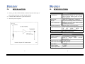
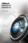
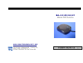
MA-19/25/66/67
Mobile GPS Antenna
SAN JOSE TECHNOLOGY, INC.
11F.,No.2,Sec.4, Jhongyang Rd. , Tucheng City,
Taipei County ,Taiwan (R.O.C.)
Tel: 886-2-2269-4456 Fax: 886-2-2269-4451
USER'S MANUAL
Rev. C
San Jose Technology, Inc.
I.
San Jose Technology,Inc.
V.
PREFACE
Technical Drawing
This text specifies the basic operational characteristics of the active
GPS antenna modules MA-19/MA-25/MA-66/MA-67 under a standard
test condition of 3V DC (MA-19)/ 5V DC (MA-25/66/67) & 25oC/
50% R.H.
II.
INTRODUCTION
MA-19/MA-25/MA-66/MA-67
is
the
integration
of
a
high
performance GPS patch antenna and a state-of-the-art low noise
amplifier into a very low profile/ extremely compact/ fully waterproof
enclosure which, when connected to a GPS receiver with 3V DC or 5V
DC antenna power, provides excellent signal amplification and
out-band filtering & rejection.
1
6
San Jose Technology,Inc.
San Jose Technology,Inc.
IV.
III.
INSTALLATION
SPECIFICATIONS
1. Secure your MA-19/MA-25/MA-66/MA-67 antenna to the top of
your vehicle and carry its cable into the vehicle.
PHYSICAL
Construction:
2. Link the cable connector to your GPS receiver.
3. Start with your navigation.
Dimension:
Weight:
Color of Radome:
Standard Mounting:
Optional Mounting 1:
Optional Mounting 2:
Polycarbonate-radome at top, die-cast
shell at bottom/ rubber gasket for water
seal in between
58mm (L) x 48mm (W) x 15mm (H)
65 grams (excluding cable & connector)
Standard in dark gray, other colors
available upon request
Magnet mount with two magnets
Screw mount with two M3 tapped holes
on
the
plastic
flange
of
MA-19/MA-25/MA-66/MA-67
Customized metal sheet
ANTENNA ELEMENT
Center Frequency:
1575.42 MHz +/- 1.023 MHz
Polarization:
R.H.C.P.
(Right
Hand
Polarization)
Absolute Gain at Zenith: +5 dBi typically
Gain at 10o Elevation: -1 dBi typically
Axial Ratio:
3 dB max.
Output VSWR:
1.8 Max.
Output Impedance:
50 ohm
5
2
Circular
San Jose Technology,Inc.
San Jose Technology,Inc.
LOW NOISE AMPLIFIER
Center Frequency:
1575.42 MHz +/- 1.023 MHz
Gain:
MA-19: 27 dB typically
MA-25: 26 dB typically
MA-66: 30 dB typically
MA-67: 30 dB typically
Band Width:
2 MHz min.
Noise Figure:
MA-19: 1.3 max.
MA-25: 2.6 max.
MA-66: 1.5 max.
MA-67: 2.0 max.
Out of Band Attenuation:
20dB min. @F0 +/- 50MHz
MA-67: 30dB min. @F0 +/- 50MHz
Supply Voltage:
MA-19: 2.5~4.5V DC
MA-25: 3.0~5.0V DC
MA-66: 4.5~5.5V DC
MA-67: 4.5~5.5V DC
Current Consumption:
MA-19: 5.5 mA +/- [email protected]
MA-25: 11 mA +/- 2 mA@5V
MA-66: 28 mA +/- 3 mA
MA-67: 28 mA +/- 3 mA
VSWR:
2.0 max.
Output Impedance:
50 ohm
OVERALL PERFORMANCE (Antenna Element, LNA & Cable)
Center Frequency:
MA-19: 20 dB typically
MA-25: 25 dB typically
Gain:
MA-66: 27 dB typically
MA-67: 27 dB typically
MA-19: 1.3 max
MA-25: 2.6 max.
Noise Figure:
MA-66: 2.0 max.
MA-67: 2.0 max.
Band Width:
2 MHz
Axial Ratio:
3 dB max.
VSWR:
2.0 max
Output Impedance:
50 ohm
ENVIRONMENTAL
CABLE & CONNECTOR
RF Cable:
5 meter RG174/U (standard), other length
available
Pulling Strength:
6 Kg./5 sec. with molded plastics on connector
end for strain relief
Connector Available:
BNC, TNC, FME, GT5, MCX (OSX), SMA,
SMB or SMC in straight or right angle type
Optional Adapters:
FME~MCX,
FME~BNC,
FME~SMB, FME~TNC
3
1575.42 MHz
Operating Temperature
-30oC~+85oC
Storage Temperature:
-40oC~+90oC
Relative Humidity:
95% non-condensing
Waterproof:
100% waterproof
FME~SMA,
4