1
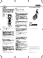
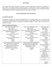
Ⅲ. PRODUCT FEATURES
GDM-357
(RMS value of sinewave)
Display Count: 1999.
GDM-357
Auto Power Off.
Temperature Range: Working:0℃~ 40℃(32℉ ~ 104℉);
Storage: -10℃~ 50℃(14℉ ~ 122℉).
Low Battery Indication:
on upper left corner of LCD.
Data Hold
(Main unit+holster+tilt stand+battery, excluding test leads)
Ⅳ. TECHNICAL SPECIFICATIONS
RMS.
Note: At 200MΩ range, the instruments normally displays 10 digits when the test leads are
shorted. Please subtract 10 digits from the subsequent measurement readings.
Relative Humidity ≤65% for measurements at 200MΩ range.
GDM-357
GDM-357
>50µF, for reference only.
Ⅰ. OVERVIEW
The brand-new GDM-357 is a 2000-count handheld digital multimeter featuring remarkably
stable and reliable operation. It is designed with large-scale integrated circuits,
a dual integral A/D converter and also offers overload protection for all ranges. The DMM can
measure DC&AC voltage, DC&AC current, resistance, capacitance, diode, transistor,
temperature, frequency, battery and continuity, which makes it a perfect solution for your work.
Ⅱ.
Input
RMS.
400Hz, 40mVrms
discharging the capacitor.
GDM-357
SAFETY INFORMATION
GDM-357
This instrument is designed and manufactured in compliance with: GB4793, IEC61010-1,
IEC1010-2-032, CAT.I 1000V,CATII 600V, Pollution Degree 2 and Double Insulation standards.
Warning
Please operate the instrument as specified in the manual, otherwise the protection offered
by the instrument would be compromised.
Continuity and Diodes
(RMS value of sinewave)
test leads
DC current
The red and black test leads should be inserted in the proper terminals and ensured with
good contact.
GDM-357
Switching the range
Use only the replacement fuse with the same model or identical electrical specifications.
AC current
compromised.
Clean the instrument casing with slightly damp cloth and mild agent. No abrasives and
solvents are allowed.
International Electrical Symbols
GDM-357
Resistance≤10Ω, the buzzer sounds;
>10Ω, the buzzer doesn't
necessarily sound;
Display approximate resistance
value, unit: Ω.
P/N:82DM-35700M01
2) Set the rotary switch to A
Ⅴ.
near the input terminals
range; Connect test leads to the tested circuit in series.
Measuring Resistance
1) Insert test leads into input terminals(Red to Ω and black to COM).
2) Set the rotary switch to Ω range; Connect test leads to tested resistor in parallel.
Multimeter Description
Rotary switch
Input Terminals
all capacitors
Measuring Capacitance
Ⅶ.
1) Although the capacitance ranges have been protected internally, you still need to discharge
all tested capacitors so as to avoid any damage to the instrument or any measurement error.
Measuring DC Voltage
1) Insert test leads into input terminals(Red to V and black to COM).
2) Set the rotary switch to range; Connect test leads to the power or load under test,
and the positive polarity of the test end will indicate.
Measuring Temperature
1)
terminals
Operating Manual
Test Leads
1 pc
1 pair
1 pc
The content of this manual is subject to changes without notice.
Testing Diodes and Continuity
1) Insert test leads into input terminals(Red to VΩ and black to COM,"+" for the red test lead).
Then set the rotary switch to
、 ; Connect test leads to tested diode. The displayed
reading is the approximate value of forward voltage drop of diode.
2) Connect test leads to the circuit under test, if the resistance between two tested ends
is <10 Ω , the built-in buzzer sounds.
Measuring AC Voltage
1) Insert test leads into input terminals(Red to V and black to COM).
2) Set the rotary switch to V range; Connect test leads to the power or load under test.
Auto Power Off
1) Auto Power Off
2)
power off,
Ⅵ.
Measuring DC current
1) Insert the black test lead into COM terminal. For current≤200mA, insert the red test lead into
mA terminal. If current goes up to 10A, insert red test lead into 10A terminal.
2) Set the rotary switch to A
range; Connect test leads to the tested circuit in series.
The polarity of red test lead will show.
randomly
voltages higher than 1000V DC or 750AC RMS.
current ranges
test leads
A
Measuring AC Current
1) Insert the black test lead into COM terminal. For current≤200mA, insert the red test lead into
mA terminal. If the current goes up to 10A, insert red test lead into 10A terminal.
the test leads from input terminals.
This manual contains proprietary information, which is protected by copyright. All rights are
reserved. No part of this manual may be photocopied, reproduced or translated to another
language without prior written consent of Good Will company.
The information in this manual was correct at the time of printing. However, Good Will continues
to improve products and reserves the rights to change specification, equipment, and maintenance
procedures at any time without notice.
Good Will Instrument Co., Ltd.
No. 7-1, Jhongsing Rd., Tucheng Dist., New Taipei City 236, Taiwan