1
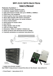
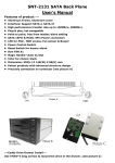
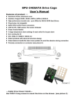
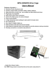
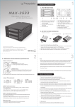
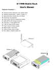
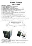
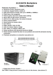
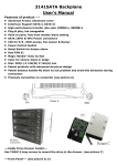
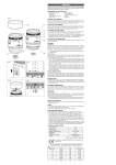
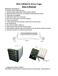
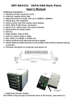
S-46WM Backplane User’s Manual Features of product -- Aluminum frame, aluminum tray and plastic bezel Interface: Support SATA-I, II, III & SAS I, II, Compatible to use with 3.5” or 2.5” SATA, SAS HDD High performance transfer rate : Max up to 6Gbps for SAS-II & SATA-III Plug & play, hot swappable for 4 x 3.5” HDD or 4 x 2.5” HDD SATA 15Pin & 4Pin Power connectors LED for P/S, HDD access, Fan sensor & Buzzer, LED On/Off setting switch Power Control Switch for each HDD 3-stage temperature alarm settings & reset switch for buzzer alarm 8cm cooling fan x 1 and High/Low stage adjustable fan speed Patent handle design with mechanical lock and advanced structure design Color for choice: black or beige Patent balance handle-No skew in/out problem & avoid the abrasion during connection Precisely connection on connector (see picture A) Dim: 202(L) X 146(W) X 126(H) mm Weight : 1.7 Kgs --- Caddy Drive Drawer Install --1) Use TM#6*4( for 3.5” HDD) & IM3*3.5(for 2.5” HDD) screws to mount the drive on the drawer. (see picture C) 2) With anti-shock stainless side springs on both side to reduce vibration (C1) Front Panel -(see picture D, E) D-1--- Reset Switch for buzzer alarm and over- heating LED When overheating occurs(default setting is 60℃) the buzzer alarms and the temperature LED turns red, meanwhile, buzzer is alarming and LED is blinking. Press the Reset Switch to stop the alarm, and LED goes off. D2--- D-5 (HD1〜HD4, Power SW and LED): Power on, LED indicates Green. Orange color is blinking while HDD is in accessing D-6--- Fan sensor LED: LED is indicating Green when powered on. When fan failed, LED turns Red. D7--- Carrier Safety Lock The safety lock safeguards the hard disk in the correct position and prevents it bouncing out while HDD is working. (see Picture E). Rear View Description (Picture F): Picture E POWER1: 4pin Power connector POWER2: 15pin Serial ATA Power connector [ Two types power for ---Rear View--- (see picture F) connection (4pin power & 15pin SATA power ). Use the 4pin power connector, or the 15pin power connector]. (Note: Can mix using 4pin and 15pin powers). Suggestion: At least 2 power, and 3 is better). HD1—HD4: 7pin Serial ATA Signal connector lJP1: Temperature setting jumper(default is 60℃) lJP3: Extension function jumpers FLEDR: Fan failure detection (red) FLED+: Fan failure detection (+) FLEDG: Fan failure detection (green) RESET: Reset Switch for buzzer alarm and Overheating LED TLEDR: Temperature detection (red) 5V+: 5V Power TLEDG: Temperature detection (green) GND:Grounded LED Switch a) When LED switch is set to “enable “position”, LED indicates Green when powered on and Orange color blinking for HDD accessing [ In this case, the HDD does not spin up until the SATA initial signal is received ]. b) When LED switch is set to “disable” position, LED always indicates SOLID GREEN both for HDD being powered on and HDD being accessing. [ In this case, the hard drive is spinning up when the system power is turned on ].