1
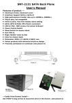
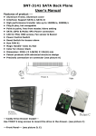
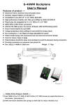
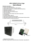
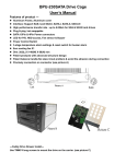
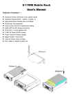
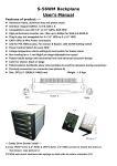
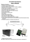
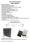
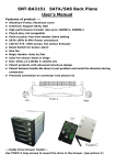
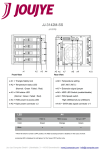
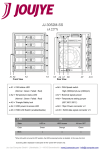
S-36WM Backplane User’s Manual Features of product -- Aluminum frame, aluminum tray and plastic bezel Interface: Support SATA-I, II, III & SAS I, II, Compatible to use with 3.5” or 2.5” SATA, SAS HDD High performance transfer rate : Max up to 6Gbps for SAS-II & SATA-III Plug & play, hot swappable for 3 x 3.5” HDD or 3 x 2.5” HDD SATA 15Pin & 4Pin Power connectors LED for P/S, HDD access, Fan sensor & Buzzer, LED On/Off setting switch Power Control Switch for each HDD 3-stage temperature alarm settings & reset switch for buzzer alarm 8cm cooling fan x 1 and High/Low stage adjustable fan speed Patent handle design with mechanical lock and advanced structure design Color for choice: black or beige Patent balance handle-No skew in/out problem & avoid the abrasion during connection Precisely connection on connector (see picture A) Dim: 202(L) X 146(W) X 86(H) mm Weight : 1.3 Kgs ---Caddy Drive Drawer Install--1) Use TM#6*4( for 3.5” HDD) & IM3*3.5(for 2.5” HDD) screws to mount the drive on the drawer. (see picture C) 2) With anti-shock stainless side springs on both side to reduce vibration (C1) ---Front Panel--- (see picture D) D.1--- Reset Switch for buzzer alarm and over- heating LED When overheating occurs(default setting is 60℃) the buzzer alarms and the temperature LED turns red, meanwhile, buzzer is alarming and LED is blinking). Press the Reset Switch to stop the alarm, and LED goes off. D.2--- D.4 (HD1〜HD3, Power SW and LED): Power on, LED indicates Green. Orange color blinking for HDD access) D.5--- Fan sensor LED: LED indicates Green when powered on. When fan failed, LED turns Red. D.6--- Carrier Safety Lock The safety lock safeguards the hard disks in the correct Picture E position and prevents it bouncing out while HDD is working. (see Picture E). Rear View Description (Picture F): POWER1: 4pin Power connector ---Rear View--- (see picture F) POWER2: 15pin Serial ATA Power connector [ Two types power for connection (4pin power & 15pin SATA power). Use the 4pin power connector, or the 15pin power connector. (Note: Can mix using 4pin and 15pin powers. Suggestion: At least 2 power).). HD1— HD3: 7pin Serial ATA Signal connector lJP1: Temperature setting jumper (default setting is 60℃) lJP3: Extension function jumpers (see left chart) FLEDR: Fan failure detection (red) FLED+: Fan failure detection (+) FLEDG: Fan failure detection (green) RESET: Reset Switch for buzzer alarm and Overheating LED TLEDR: Temperature detection (red) 5V+: 5V Power TLEDG: Temperature detection (green) GND:Grounded J4: Fan High/Low switch [ [High 3000rpm & LOW 2300 rpm ] LED Switch a) When LED switch is set to “enable “position”, LED indicates Green when powered on and Orange color blinking for HDD accessing [ In this case, the HDD does not spin up until the SATA initial signal is received ]. b) When LED switch is set to “disable” position, LED always indicates SOLID GREEN both for HDD being powered on and HDD being accessing. [ In this case, the hard drive is spinning up when the system power is turned on ].