1
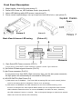
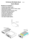
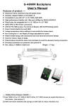
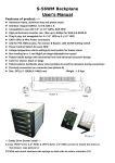
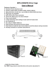
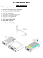
S-11WM Mobile Rack User’s Manual Features of product -- Aluminum Frame, Aluminum cover, plastic handle Interface: Support SATA - I, SATA - II, SATA - III High performance transfer rate up to 6Gbps Plug & play, hot swappable Point to point, free from master/slave setting SATA 15Pin & 4Pin Power connectors Front Fan x 1, Dust resistant door 2 LED for Power & HDD access Power Control & Keylock design Magic Handle—Auto In/Out Color for choice: black or beige Dim: 188(L) X 146(W) X 42(H) mm Front Panel Description: 1 2 3 4 Magic Handle—Auto In/Out (see picture C) Power LED: Power on, LED indicates Green. (see picture D) Amber LED blinking while HDD access. (see picture D) Power control keylock design: turn up to open and turn left to lock)—(see picture F) Picture C Back View & Access LED wiring Picture D (Picture E ) Picture E 1) 15pin Serial ATA Power connector (Pic.E-1) If your power is from SATA 15pin connector, connect it to the 15pin connector 2) 7pin Serial ATA data signal connector (Pic.E-2) 3) 4pin Power connector (Pic.E-3) If your power is not from SATA 15pin connector, then, use the 4pin power connector; the 4pin power will automatically be converted to SATA power. 4) HD LED SWITCH (See Picture E-4) 1) DIP Switch set on ENABLE – The front HDD accessing LED can work normal (Yellow color for accessing and no indication if there is no accessing) 2) DIP Switch on DISABLE—No LED indication for the front HDD accessing (*this function is designed for some special HDDs which are not recognized under normal HDD indication status but when it is set to DISABLE, the HDD can work; however, the LED indication function is invalid. This is the special design to make those special HDDs can work but without LED indication).