1
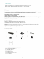
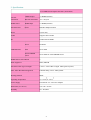
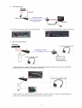
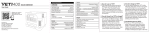
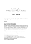
4X6 HDMI Switch/Splitter Extender over CAT.5e/6
HD4600T
User’s Manual
Version 1.0
1. Introduction
Thanks for purchasing the 4 x 6 HDMI Switch/Splitter Extender over CAT.5e/6.
Please read this Manual and retain it for reference in future if needed.
1.1 Features
Supports 1 source selected among 4 HDMI sources and the same source content can be done splitting displaying
on remote all of 6 displays and even distributing with extending through Ethernet switch 10/100.
LED indicators monitor for connection status
Supports HDMI 1.3, HDCP compliant
Supports resolution up to Full HD 1080p, 1920 x 1080 @60Hz
Each corresponding extender receiver unit (remote) links cascade-chainable additional 2 receivers for expansion.
Extended distance over CAT. 5e/6 up to 100m (point-to-point)
HDMI sources selected by front buttons
IR (Infrared Remote)
Enabled for communication of between the correspondence of
switch (Emitter cable) and receiver unit (RX) – (Receiver cable)
RS232 enabled for each communication of between the correspondence of switch and receiver unit (RX)
Supports local loop HDMI monitoring and Audio enabled
1.2 Package Contents
1. 4 x 6 HDMI Switch/Splitter Extender (TX) x 1
2. DC 5V / 2A Power Adapter x 1
3. Audio Cable 1.8m x 1
4. RS-232 Cable x 4
5. IR Emitter Cable x 4
6. Rack Mount Bracket x 2 (1 sets)
7. User’s Manual x 1
1
2. Specifications
4 x 6 HDMI Switch/Splitter Extender (Transmitter)
HDMI Output
1 x HDMI (Female)
Console
Connectors
RS-232Control Port
HDMI source
HDMI Input
4 x HDMI (Female)
Extension Port
RJ-45
Full HD 1080p Extension
4 x 3.5Ø jack
RJ-45
6 (Line Out)
Audio
Supports Stereo Audio
IR
Unidirectional 38KHz
LED Indicators
Power
Red LED
Link
Green LED
Selected HDMI
source
Green LED for selected HDMI source
HDMI Source Select Button
5
DDC Supported
DDC, DDC2B
Extension Cable Type & Length
CAT.5e / CAT.6 Max. Length: 100m (point-to-point)
Max. Video Resolution Supported
Full HD 1080p, 1920 x 1080 @60Hz
Housing material
Metal
Operating Temperature
32 - 122 F (0 - 50 C)
Power Supply
External DC 5V / 2A Power Adapter
Dimension (L x W x H)
275 x 98 x 38 mm
Humidity
0% - 80% RH
2
3. Connection between Switch Extender (Transmitter) and Receiver
Transmitter
Receiver
Choose one available RJ-45 port of the Extender Receiver (RX) connected with the
Switch Extender (Transmitter) over CAT.5e or CAT.6 cable.
Remarks:
The Network Switch 10/100 enough could be transceiver for extending distance.
Please refer to the following connections:
(1). The Network Switch is linked between Switch Extender (Transmitter) and Receiver.
(2). The Network Switch is possibly connected between Receiver and Receiver.
5
4.
IR Connection
5. RS-232 Connection
Connect the RS-232 adapter cable to Switch Extender (Transmitter) RS-232 3.5mm jack, and another
end of the cable is connected to the RS-232 port of PC.
Connect the RS-232 adapter cable to Extender Receiver (RX)’s RS-232 3.5mm jack, and another end
of the cable is connected to the RS-232 port of the 3rd party’s device.
6
Disclaimer
Information in this document is subject to change without notice. The manufacturer does not make any representations or warranties
(implied or otherwise) regarding the accuracy and completeness of this document and shall in no event be liable for any loss of profit
or any other commercial damage, including but not limited to special, incidental, consequential, or other damages.
No part of this document may be reproduced or transmitted in any form by any means, electronic or mechanical, including
photocopying, recording or information recording and retrieval systems without the express written permission of the manufacturer.
All brand names and product names used in this document are trademarks, or registered trademarks of their respective holders.
FCC Statement
This device generates and uses radio frequency and may cause interference to radio and television reception if not installed and
used properly. This has been tested and found to comply with the limits of a Class B computing device in accordance with the
specifications in Part 15 of the FCC Rules. These specifications are designed to provide reasonable protection against such
interference in a residential installation. However, there is no guarantee that interference will not occur in a particular installation. If
this device does cause harmful interference to radio or television reception, which can be determined by plugging the device in and
out, the user can try to correct the interference by one or more of the following measures:
Reorient or relocate the receiving antenna.
Increase the separation between the device and receiver.
Connect the computer into an outlet on a circuit different from that to which the receiver is connected.
Consult the dealer or an experienced radio/TV technician for help.
CE / FCC
2R40M4088