1
HT32 Series In-System / In-Application
Programmer User Manual
Revision: V1.00
Date: �������������
July 14, 2011
32-bit ARM Cortex-M3 MCU
HT32 Series
Table of Contents
1 Introduction.............................................................................................................. 5
About This Document............................................................................................................. 5
HT32 Flash Programmer Overview........................................................................................ 5
2 Using the HT32 Flash Programmer........................................................................ 7
Installing the HT32 Flash Programmer................................................................................... 7
HT32 Flash Programmer Quick Start................................................................................... 11
Functional Description.......................................................................................................... 14
Connection....................................................................................................................................... 14
Image Selection............................................................................................................................... 15
Protection Settings........................................................................................................................... 15
Flash Operations............................................................................................................................. 16
Processing Status and Results Message........................................................................................ 17
Auto-Connect and Auto-Programming............................................................................................. 18
Device Status................................................................................................................................... 19
Read Flash Memory........................................................................................................................ 20
Project Operations........................................................................................................................... 21
Developing Flash Programmers for the HT32 Series MCU.................................................. 22
Introduction...................................................................................................................................... 22
Windows DLL API Descriptions....................................................................................................... 24
Getting Started with the Example Project........................................................................................ 31
3 Using the ISP and IAP Firmware.......................................................................... 33
HT32 Flash Command Protocol........................................................................................... 33
Protocol Descriptions....................................................................................................................... 33
Command Format ........................................................................................................................... 34
Command Descriptions................................................................................................................... 35
Using the ISP Bootloader..................................................................................................... 39
IAP Example Code............................................................................................................... 40
Introduction...................................................................................................................................... 40
IAP Text Mode Example Code......................................................................................................... 43
IAP UI Mode Example Code............................................................................................................ 46
Updating the IAP Firmware.............................................................................................................. 48
Rev. 1.00
2 of 49
July 14, 2011
Table of Contents
ISP and IAP Overview............................................................................................................ 6
32-bit ARM Cortex-M3 MCU
HT32 Series
List of Figures
Rev. 1.00
1. ISP/IAP Programming Tools System Architecture..................................................................... 5
2. Memory organization of ISP and IAP......................................................................................... 6
3. HT32 Flash Programmer Installation – Welcome Page............................................................ 7
4. HT32 Flash Programmer Installation – Select Installation Path................................................ 8
5. HT32 Flash Programmer Installation – Ready to Install Page................................................... 9
6. HT32 Flash Programmer Installation – Completion................................................................. 10
7. Start HT32 Flash Programmer.................................................................................................11
8. HT32 Flash Programmer Main Screen.....................................................................................11
9. Connection Status................................................................................................................... 12
10. Operation Success Screen.................................................................................................... 12
11. Read Flash Memory.............................................................................................................. 13
12. Connection and Related Settings.......................................................................................... 14
13. Image Selection..................................................................................................................... 15
14. Protection Settings................................................................................................................ 15
15. Flash Operation Related Settings.......................................................................................... 16
16. Processing Status and Results Message.............................................................................. 17
17. Auto-Connect and Auto-Programming................................................................................... 18
18. Chip Status............................................................................................................................ 19
19. Read Flash Memory.............................................................................................................. 20
20. Project File Operations.......................................................................................................... 21
21. VC++6.0 ISPCmd.dll Example Code..................................................................................... 31
22. Configure the COM Port and Baud Rate............................................................................... 31
23. Holtek Flash Programmer Protocol....................................................................................... 33
24. IAP Example Code Architecture............................................................................................ 40
25. IAP mode Boot Flow.............................................................................................................. 41
26. IAP Example Code Folders................................................................................................... 42
27. Application Text Menu ........................................................................................................... 45
28. IAP Text Mode Text Menu ..................................................................................................... 45
29. RAM Executed IAP Text Mode Text Menu............................................................................. 48
3 of 49
July 14, 2011
List of Figures
Figure
Figure
Figure
Figure
Figure
Figure
Figure
Figure
Figure
Figure
Figure
Figure
Figure
Figure
Figure
Figure
Figure
Figure
Figure
Figure
Figure
Figure
Figure
Figure
Figure
Figure
Figure
Figure
Figure
32-bit ARM Cortex-M3 MCU
HT32 Series
List of Tables
Rev. 1.00
1. Processing Status and Results Message.................................................................................. 17
2. Windows DLL API...................................................................................................................... 22
3. Return Code of API................................................................................................................... 23
4. ISP_SetupSerialPortConnection Function................................................................................ 24
5. ISP_CloseSerialPortConnect Function..................................................................................... 24
6. ISP_ErasePage Function.......................................................................................................... 25
7. ISP_EraseMass Function.......................................................................................................... 25
8. ISP_BlankCheck Function........................................................................................................ 26
9. ISP_WriteProgramB Function................................................................................................... 26
10. ISP_CRCCheck Function........................................................................................................ 27
11. ISP_ReadData Function.......................................................................................................... 27
12. ISP_Execute Function............................................................................................................. 28
13. ISP_Exit Function.................................................................................................................... 28
14. ISP_Reset Function................................................................................................................ 28
15. ISP_IsConnectedToDevice Function....................................................................................... 29
16. ISP_GetTransProgress Function............................................................................................ 29
17. ISP_GetInformation Function.................................................................................................. 29
18. nCode definition of ISP_GetInformation Function................................................................... 30
19. Command Description............................................................................................................. 34
20. Get Information Command (i).................................................................................................. 35
21. TYPE Definition of Get Information Command....................................................................... 35
22. Mass/Page Erase Command (e)............................................................................................. 36
23. Blank Check Command (b)..................................................................................................... 36
24. Program/Verify Command (w)................................................................................................. 37
25. CRC check (c)......................................................................................................................... 37
26. Execution, Exit, and Reset Command (g)............................................................................... 38
27. Read Memory Command (r)................................................................................................... 38
28. Text Mode Source Files........................................................................................................... 43
29. IAP UI mod Source Files......................................................................................................... 46
4 of 49
July 14, 2011
List of Tables
Table
Table
Table
Table
Table
Table
Table
Table
Table
Table
Table
Table
Table
Table
Table
Table
Table
Table
Table
Table
Table
Table
Table
Table
Table
Table
Table
Table
Table
32-bit ARM Cortex-M3 MCU
HT32 Series
1
Introduction
About This Document
HT32 Flash Programmer Overview
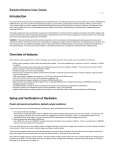
The main tasks of the HT32 Flash Programmer are for code/data programming of user applications
and for flash protection setting. Additionally, the current status of the target device such as device
name, flash size, code/data information and the protection settings can be queried and displayed on
the GUI. The Flash Programmer communicates with the ISP/IAP firmware via the UART interface
and then uses pre-defined protocols/commands to apply flash operations. Users can select flash
images, adjust the flash protection settings and assign suitable flash operations through the GUI.
After a few simple steps, the image will be downloaded to the target device automatically.
HT32 Series MCU
Preloaded
ISP Bootloader
System & Peripherals
HT32 Flash Command Protocol
Communication Interface
HT32 Flash Command Protocol
Holtek HT32 Flash Programmer
Flash Memory
IAP
Example
0x00000000
System & Peripherals
HT32 Flash Command Protocol
Host
0x1F000000
HT32 Series MCU
Preloaded
ISP Bootloader
Flash Memoty
0x00000000
Device
Figure 1. ISP/IAP Programming Tools System Architecture
Rev. 1.00
5 of 49
July 14, 2011
Introduction
This document describes how to use the In-System Programming (ISP) and In-Application
Programming (IAP) tools for the HT32 series of microcontrollers. The contents are divided into
two main areas, the PC-Based HT32 Flash Programmer user Interface and the ISP/IAP firmware.
A short overview of the HT32 Flash Programmer and ISP/IAP in the following section will assist
with initial understanding of the architecture. In a following chapter, a description of how to
use the HT32 Flash Programmer will be provided and information regarding flash programmer
development will also be given. A further chapter will discuss details regarding the ISP and IAP
firmware including command protocols, ISP Boot loader and also the IAP example code.
32-bit ARM Cortex-M3 MCU
HT32 Series
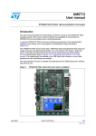
ISP and IAP Overview
The ability to update application firmware is an important consideration for end products with
limited communication interfaces and embedded flash memory systems. A software controlled
Flash programming method is thus required to erase and program the Flash memory via the
predefined communication interface. In-System Programming, ISP, provides a preloaded ISP
bootloader that will communicate with the PC software following Holtek’s HT32 Flash Command
Protocols to update the Flash memory.
ISP
0x400 or above
IAP
User Data
944 bytes or above
0x50
0x40
0x30
Option Byte
I_DDATE
I_DSIZE
I_CRC1
Reserved
I_CDATE
I_CSIZE
I_CRC0
Reserved
OB_CK
Reserved
Reserved
Reserved
OB_CP
Reserved
Reserved
Reserved
OB_PP0
OB_PP1
OB_PP2
OB_PP3
0x20
0x10
0x1FF0_0000
0x00
ISP
Bootloader
0x1F00_0000
UART
ISP
Bootloader
.
.
.
Main
Option Byte
UI Mode
.
.
.
Main
Holtek HT32
Flash Programmer
IAP
0x0000_0000
Text Mode
0x0000_0C00 (3K, UART)
0x0000_0000
Figure 2. Memory organization of ISP and IAP
Rev. 1.00
6 of 49
July 14, 2011
Introduction
In-Application Programming, IAP, plays the same role except that it implements the programming
procedure while the application is running. The IAP code, just like a normal application, must first
be programmed into the Flash Memory using other methods such as an ISP, a USB debugger or a
Flash Writer. The area with dotted line in the figure below is the Flash memory that can be updated
by ISP/IAP.
32-bit ARM Cortex-M3 MCU
HT32 Series
2
Using the HT32 Flash Programmer
The following section describes how to install the HT32 Flash Programmer, download an image,
configure the option byte and also how to develop a custom flash programmer for the HT32 series
of MCUs using Holtek’s Windows DLL.
The recommended system requirements are:
▀
▀
▀
▀
▀
A host computer running Microsoft® Windows® XP, Vista, or Windows® 7
1 GB RAM and 20 MB of available hard-disk space is recommended
XGA (1024x768) colour monitor or higher display resolution
A mouse or other pointing device
A CD-ROM drive - optional
The following steps show how to install the HT32 Flash Programmer into the computer.
Step 1: Obtain the latest version of the HT32 Flash Programmer from the Holtek website or from
the CD-ROM supplied by Holtek. The required filename is similar to “HT32_Flash_
Programmer_Vnnn.exe” where “nnn” represents the version number.
Step 2: Double-click on “HT32_Flash_Programmer_Vnnn.exe” and press the “Next” button on the
dialog below to continue.
Figure 3. HT32 Flash Programmer Installation – Welcome Page
Rev. 1.00
7 of 49
July 14, 2011
Using the HT32 Flash Programmer
Installing the HT32 Flash Programmer
32-bit ARM Cortex-M3 MCU
HT32 Series
Step 3: The default installation path is “C:\Program Files\Holtek HT32 Series\HT32 Flash
Programmer”. Select the “Browse” button to change the path and select the “Next” button
to continue when the path has been chosen.
Using the HT32 Flash Programmer
Figure 4. HT32 Flash Programmer Installation – Select Installation Path
Rev. 1.00
8 of 49
July 14, 2011
32-bit ARM Cortex-M3 MCU
HT32 Series
Step 4: Press the “Install” button to start the installation when the “ready to install” screen
appears.
Using the HT32 Flash Programmer
Figure 5. HT32 Flash Programmer Installation – Ready to Install Page
Rev. 1.00
9 of 49
July 14, 2011
32-bit ARM Cortex-M3 MCU
HT32 Series
Step 5: Once the installation has finished, a completion page will appear as shown below. Choose
whether or not to view the release note or to launch the HT32 Flash Programmer. Press the
“Finish” button to complete the installation process.
Using the HT32 Flash Programmer
Figure 6. HT32 Flash Programmer Installation – Completion
Rev. 1.00
10 of 49
July 14, 2011
32-bit ARM Cortex-M3 MCU
HT32 Series
HT32 Flash Programmer Quick Start
To start using the Flash Programmer, several components are required as listed below:
▀ A HT32 series MCU target board
®
®
®
▀ A host computer running Microsoft Windows XP, Vista, or Windows 7
▀ Full HT32 Flash Programmer installation as described earlier.
Step 1: Connect the target board to the COM port of the PC with an RS232 cable.
Step 3: Double-click “Start → All Programs → Holtek HT32 Series → Holtek HT32 Flash
Programmer → HT32 Flash Programmer” to run the program.
Figure 7. Start HT32 Flash Programmer
Step 4: Tick “Project → New Project” to restore the default value settings. Change the COM port
if required and confirm that the Baud Rate is set to 115200.
Figure 8. HT32 Flash Programmer Main Screen
Rev. 1.00
11 of 49
July 14, 2011
Using the HT32 Flash Programmer
Step 2: Make sure the BOOT0 and BOOT1 pins are setup as follows:.
ISP: BOOT1 = 0, BOOT0 = 0 or BOOT1 = 0, BOOT0 = 1
Refer to the user manual for each device
IAP: BOOT1 = 1, BOOT0 = 0
32-bit ARM Cortex-M3 MCU
HT32 Series
Step 5: Turn on the device power and press the “Connect” button to connect. If the connection is
successful, a “Connected” status message will appear. The device name will also appear as
shown below. Press the “Programming” button to start the download operation.
Step 6: If the operation succeeds, an “Operations success” message will appear as shown below.
Figure 10. Operation Success Screen
Rev. 1.00
12 of 49
July 14, 2011
Using the HT32 Flash Programmer
Figure 9. Connection Status
32-bit ARM Cortex-M3 MCU
HT32 Series
Step 7: Press the “Connect” button to re-connect the device and change the tab to the “Memory
– Code” page. Press the “Read” button to read the data from the flash. Since the default
setting has been chosen, a dummy data “image.bin” will have been programmed into the
Flash memory as shown below for testing.
Now, the HT32 Flash Programmer is ready for use. For more information regarding each function,
refer to the following sections.
Rev. 1.00
13 of 49
July 14, 2011
Using the HT32 Flash Programmer
Figure 11. Read Flash Memory
32-bit ARM Cortex-M3 MCU
HT32 Series
Functional Description
This section describes the HT32 Flash programmer operations with a detailed description of each
function.
Connection
Figure 12. Connection and Related Settings
Rev. 1.00
14 of 49
July 14, 2011
Using the HT32 Flash Programmer
The HT32 Flash Programmer communicates with the target device via an RS232 interface. The
related programmer settings are shown below. After ensuring that the COM port and baud rate are
set correctly select the “Connect” button to make the required connection. How to use the AutoConnect function will be discussed in a later chapter.
32-bit ARM Cortex-M3 MCU
HT32 Series
Image Selection
Select the “…” which is the folder browse button to select the Code or Data image file. Both binary
and hex formats are supported. Information regarding the file date, file size and its CRC value will
also be updated if the target is connected. The Flash operation will be applied to the Code/Data
area only when its Code or Data checkbox has been checked.
Using the HT32 Flash Programmer
Figure 13. Image Selection
Protection Settings
Select the “Configure” button to configure the protection settings as shown below. The actual
Option Bytes value is shown in the left side of the setting window. This will be updated
dynamically when the checkbox status is changed. Use the individual “All” checkboxes to select
a specific line. Clicking the “OK” button will retain the related values. Note that the Option Byte
Write and Security protection functions are invalid in the IAP mode.
Figure 14. Protection Settings
Rev. 1.00
15 of 49
July 14, 2011
32-bit ARM Cortex-M3 MCU
HT32 Series
Flash Operations
The major objective of the Flash operations is for Code, Data and Protection Settings. These
various operations will only be executed when their respective checkbox has been selected, i.e. the
flash operation can be updated partially.
Figure 15. Flash Operation Related Settings
Rev. 1.00
16 of 49
July 14, 2011
Using the HT32 Flash Programmer
The “Necessary pages” and “All pages” options are used to decide the behavior of the Erase and
Blank Check functions. If “Necessary pages” is selected, then only the specified Flash pages will
be affected. The page target range will depend on the image size. If “All pages” is selected, then,
all the Flash memory pages will be erased or blank checked. This function can be used to erase all
the device contents. The following figure shows the Flash operation related settings.
32-bit ARM Cortex-M3 MCU
HT32 Series
Processing Status and Results Message
The processing status and their results can assist with understanding the operational situation. This
is shown in the figure below. A full message description is shown in Table 1.
Table 1. Processing Status and Results Message
Processing Status
Result Message
Descriptions
Disconnect
—
Programmer is in the idle mode. COM port is
closed.
Connecting
—
Programmer trying to connect to the device.
Connected
—
Device is connected.
Erasing
—
Erase operation in progress.
Blank Checking
—
Blank check operation in progress.
Programming
—
Programming operation in progress.
Verifying
—
Verify operation in progress.
CRC Checking
—
CRC check in progress.
Operation success
All operations successful
Erase Failed
Erase operation failed.
Disconnect, Connected, or Connecting Blank Check Failed
(According to the setting of AutoProgram Failed
Connect and Run)
Rev. 1.00
Blank check operation failed.
Program operation failed.
Verify Failed
Verify operation failed.
CRC Check Failed
CRC check failed.
17 of 49
July 14, 2011
Using the HT32 Flash Programmer
Figure 16. Processing Status and Results Message
32-bit ARM Cortex-M3 MCU
HT32 Series
Auto-Connect and Auto-Programming
The HT32 Flash Programmer provides Auto-Connect an Auto-Programming functions. The
following figure shows how these two functions are used. When the Auto-Connect function is
enabled, the HT32 Flash Programmer is connected automatically when launched or re-connect
when any previous operation has finished. The HT32 Flash Programmer will then start Flash
operations automatically when the device is connected. The Auto-Connect and Auto-Programming
functions will help to reduce the manual operation time during high volume device programming.
Using the HT32 Flash Programmer
Process finish
Flash
Programmer
Start
Disconnect
Processing
No response from device
Connect
or
Auto-Connect
Idle
Programming
or
Auto-Programming
Connect
Disconnect
Connected
Disconnect
Device
Probing
Connecting
Get response from device
Device on
line checking
Figure 17. Auto-Connect and Auto-Programming
Rev. 1.00
18 of 49
July 14, 2011
32-bit ARM Cortex-M3 MCU
HT32 Series
Device Status
After the programmer is connected, information such as device name, Flash size, connection mode
will be queried by the HT32 Flash Programmer and displayed under the Chip Status tab. If the
device has been programmed before, the image information such as date, size and CRC value will
be shown in the upper right area. The current protection settings will also be displayed.
Using the HT32 Flash Programmer
Figure 18. Chip Status
Rev. 1.00
19 of 49
July 14, 2011
32-bit ARM Cortex-M3 MCU
HT32 Series
Read Flash Memory
The “Memory - Code” and “Memory - Data” tabs provide “memory display” and “save as”
functions for debugging purposes. After the programmer has been connected, enter the start
address, length and select the “Read“ button to execute a read operation. The HT32 Flash
Programmer UI will receive the memory data and display it on the screen. Right click on the
memory window to change the display width to byte, half-word or word as shown below. Click the
“Save as” button to save the specific contents to a file in binary format for later use.
Using the HT32 Flash Programmer
Figure 19. Read Flash Memory
Rev. 1.00
20 of 49
July 14, 2011
32-bit ARM Cortex-M3 MCU
HT32 Series
Project Operations
Flash
Programmer
Start
Project (F)
New Project
Open Project...
Ctrl+O
Save Project
Ctrl+S
Save Project As...
setting.ini
Save
New
Current
Setting
Default
Value
Open
Open
default.ini
Save As
product1.ini
product2.ini
*.ini
Figure 20. Project File Operations
Rev. 1.00
21 of 49
July 14, 2011
Using the HT32 Flash Programmer
The following figure shows the project operations. Use these functions to “create”, “open”, “save”,
and “save as” the HT32 Flash Programmer settings. Once the Flash Programmer is running, the file
“setting.ini” will be loaded as a default file to reduce the setting time. When any settings have been
changed, “Save Project” will save the value to the “setting.ini” file. All the controls are reset to the
default value if “New Project” in the “Project” menu is selected. This default values are saved in
the “default.ini” file that is located in the HT32 Flash Programmer installation path. “Save Project
As” will save the settings to another specific file while “Open Project” will open the selected file as
the current setting. Refer to the figure below for the details.
32-bit ARM Cortex-M3 MCU
HT32 Series
Developing Flash Programmers for the HT32 Series MCU
Introduction
Table 2. Windows DLL API
Type
Connect
Control
Status
Rev. 1.00
API Name
Description
ISP_SetupSerialPortConnection
Connect to the programmer
ISP_CloseSerialPortConnect
Close the programmer connection
ISP_ErasePage
Erase page
ISP_EraseMass
Mass erase
ISP_BlankCheck
Blank check
ISP_WriteProgramB
Program or verify
ISP_CRCCheck
Flash memory CRC check
ISP_ReadData
Read memory from device
ISP_Execute
Execute user program
ISP_Exit
Exit command mode
ISP_Reset
Reset the programmer
ISP_IsConnectedToDevice
Check the connection
ISP_GetTransProgress
Obtain progress rate of program or verify
ISP_GetInformation
Obtain device information
22 of 49
July 14, 2011
Using the HT32 Flash Programmer
Holtek provides a dynamic-link library (“ISPCmd.dll”) for Flash programming operations that
implements the HT32 Flash Command Protocol and the communication APIs to communicate with
ISP or IAP firmware. Software programmers can add the DLL library into their own projects and
use the API functions to program devices in the same way as the HT32 Flash Programmer. The
following two tables are the API function list and the return codes of the “ISPCmd.dll”. Detailed
information for each function will be discussed in following sections.
32-bit ARM Cortex-M3 MCU
HT32 Series
Table 3. Return Code of API
Return Code
ISP_CMD_SUCCESS
0x00
ISP_CMD_EXECUTE_FAILED
0x01
ISP_CMD_EXECUTE_BADCMD
0x02
ISP_ECHO_ERROR
0x03
ISP_BAD_FW_REPLY_DATA
0x04
ISP_SECURITY_LOCK
0x05
ISP_WRITE_PROTECT
0x06
ISP_BAD_PROGRAMMING
0x07
ISP_BAD_PROGRAMMING_NO_FIND_ACK
0x08
ISP_BAD_PROGRAMMING_TIMEOUT
0x09
ISP_BAD_PROGRAMMING_OPEN_FILE_NG
0x0a
ISP_BAD_UNABLE_EXITXMODEM
0x0b
ISP_SERIAL_PORT_OPEN_FAILED
0x0c
ISP_SERIAL_PORT_NOT_CONNECTED
0x0d
ISP_SERIAL_PORT_UNABLE_WRITE
0x0e
ISP_SERIAL_PORT_UNABLE_READ
0x0f
ISP_DEVICE_NOT_FOUND
0x10
ISP_RESET_ERROR
0x11
ISP_INVALID_PARAMETER
0x12
ISP_FUNCTION_NOT_SUPPORTED
0x13
ISP_SYSTEM_ERROR_CODE
0x14
ISP_UNKNOWN_ERR
0xff
23 of 49
Using the HT32 Flash Programmer
Rev. 1.00
Values
July 14, 2011
32-bit ARM Cortex-M3 MCU
HT32 Series
Windows DLL API Descriptions
▀ ISP_SetupSerialPortConnection
Table 4. ISP_SetupSerialPortConnection Function
API
INT ISP_SetupSerialPortConnection(INT nPort, DWORD baud_rate);
Descriptions
Open a specified serial port to connect to the programmer.
nPort: Specify the serial port
Using the HT32 Flash Programmer
Parameter
Baud_rate: Specify the baud rate
ISP_CMD_OK: Successful operation
Return
ISP_SERIAL_PORT_OPEN_FAILED: Can not open COM port
Example
If ( !ISP_SetupSerialPortConnection ( 1, 115200 ) )
{
// Unable to connect the serial port…
ISP_CloseSerialPortConnect ( );
}
▀ ISP_CloseSerialPortConnect
Table 5. ISP_CloseSerialPortConnect Function
API
VOID ISP_CloseSerialPortConnect(VOID);
Descriptions
Close the serial port.
Parameter
None
Return
None
Example
If ( !ISP_SetupSerialPortConnection ( 1, 115200 ) )
{
// Unable to connect the serial port…
ISP_CloseSerialPortConnect ( );
}
Rev. 1.00
24 of 49
July 14, 2011
32-bit ARM Cortex-M3 MCU
HT32 Series
▀ ISP_ErasePage
Table 6. ISP_ErasePage Function
API
INT ISP_ErasePage(DWORD dwStartAddr, DWORD dwEndAddr);
Descriptions
Erase page according to the parameter dwStartAddr and dwEndAddr.
Parameter
dwStartAddr: Flash memory start address
dwEndAddr: Flash memory end address
Using the HT32 Flash Programmer
ISP_CMD_OK: Successful operation
ISP_INVALID_PARAMETER: Invalid parameter
ISP_SERIAL_PORT_NOT_CONNECTED: COM port can not be connected
Return
ISP_SERIAL_PORT_UNABLE_READ: COM port can not be read
ISP_SERIAL_PORT_UNALBE_WRITE: COM port can not be written
ISP_CMD_EXECUTE_FAILED: Failed operation
Example
ISP_ErasePage(0xc00, 0xfff );
// Erase from 0xc00 to 0xfff
▀ ISP_EraseMass
Table 7. ISP_EraseMass Function
API
INT ISP_EraseMass(VOID);
Descriptions
Apply mass erase on Flash memory.
Parameter
None
ISP_CMD_OK: Successful operation
ISP_SERIAL_PORT_NOT_CONNECTED: COM port can not be connected
Return
ISP_SERIAL_PORT_UNABLE_READ: COM port can not be read
ISP_SERIAL_PORT_UNALBE_WRITE: COM port can not be written
ISP_CMD_EXECUTE_FAILED: Failed operation
Example
Rev. 1.00
ISP_EraseMass();
// Start Mass Erase
25 of 49
July 14, 2011
32-bit ARM Cortex-M3 MCU
HT32 Series
▀ ISP_BlankCheck
Table 8. ISP_BlankCheck Function
API
INT ISP_BlankCheck(DWORD dwStartAddr, DWORD dwEndAddr);
Descriptions
Execute blank check in specific range according to the parameter, dwStartAddr and
dwEndAddr.
Parameter
dwStartAddr: Flash memory start address
Using the HT32 Flash Programmer
dwEndAddr: Flash memory end address
ISP_CMD_OK: Successful operation
ISP_INVALID_PARAMETER: Invalid parameter
ISP_SERIAL_PORT_NOT_CONNECTED: COM port can not be connected
Return
ISP_SERIAL_PORT_UNABLE_READ: COM port can not be read
ISP_SERIAL_PORT_UNALBE_WRITE: COM port can not be written
ISP_CMD_EXECUTE_FAILED: Failed operation
Example
ISP_BlankCheck(0xc00, 0xfff);
// Apply blank check on 0xc00~0xfff
▀ ISP_WriteProgramB
Table 9. ISP_WriteProgramB Function
API
INT ISP_WriteProgramB(DWORD dwStartAddress, DWORD dwEndAddress, BYTE mode,
BYTE * pbValue);
Descriptions
Start Xmodem protocol for program or verify operation.
dwStartAddr: Flash memory start address
Parameter
dwEndAddr: Flash memory end address
mode: 1 for Program, 0 for verify
pbValue: Buffer pointer to which data will be written.
ISP_CMD_OK: Successful operation
ISP_INVALID_PARAMETER: Invalid parameter
ISP_SERIAL_PORT_NOT_CONNECTED: COM port can not be connected
ISP_SERIAL_PORT_UNABLE_READ: COM port can not be read
Return
ISP_SERIAL_PORT_UNALBE_WRITE: COM port can not be written
ISP_BAD_PROGRAMMING_NO_FIND_ACK: Unable to find the acknowledge
ISP_BAD_PROGRAMMING_TIMEOUT: Programming operation timeout
ISP_BAD_UNABLE_EXITXMODEM: Xmodem protocol error
ISP_BAD_PROGRAMMING: Programming error
Example
Rev. 1.00
Byte buffer[16];
buffer[0] = 0x55;
….
ISP_WriteProgramB( 0xc00, 0xc0f, 1, buffer);
address 0xc00
26 of 49
// write 16 bytes to ( Main Flash )
July 14, 2011
32-bit ARM Cortex-M3 MCU
HT32 Series
▀ ISP_CRCCheck
Table 10. ISP_CRCCheck Function
API
INT ISP_CRCCheck(DWORD dwStartAddr, DWORD dwEndAddr, BYTE *pbValue);
Descriptions
CRC check of Flash memory.
dwStartAddr: Flash memory start address
Parameter
dwEndAddr: Flash memory end address
Using the HT32 Flash Programmer
pbValue: Buffer pointer for CRC result
ISP_CMD_OK: Successful operation
ISP_INVALID_PARAMETER: Invalid parameter
ISP_SERIAL_PORT_NOT_CONNECTED: COM port can not be connected
Return
ISP_SERIAL_PORT_UNABLE_READ: COM port can not be read
ISP_SERIAL_PORT_UNALBE_WRITE: COM port can not be written
ISP_CMD_EXECUTE_FAILED: Failed operation
Example
BYTE bValue[2];
ISP_CRCCheck(0xc00, 0xfff, &bValue);
▀ ISP_ReadData
Table 11. ISP_ReadData Function
API
INT ISP_ReadData(DWORD dwStartAddress, DWORD dwEndAddr, BYTE* pbValue);
Descriptions
Read Flash memory data from device.
dwStartAddr: Flash memory start address
Parameter
dwEndAddr: Flash memory end address
pbValue: Buffer pointer to which data will be read
ISP_CMD_OK: Successful operation
ISP_INVALID_PARAMETER: Invalid parameter
ISP_SERIAL_PORT_NOT_CONNECTED: COM port can not be connected
Return
ISP_SERIAL_PORT_UNABLE_READ: COM port can not be read
ISP_SERIAL_PORT_UNALBE_WRITE: COM port can not be written
ISP_SECURITY_LOCK: Security lock is enabled
ISP_BAD_FW_REPLY_DATA: Return value from firmware is invalid
Example
Rev. 1.00
Byte buffer[16];
ISP_ReadData(0xc00, 0xc0f, buffer );
0xc00
27 of 49
// Read 16 bytes from (Main Flash) address
July 14, 2011
32-bit ARM Cortex-M3 MCU
HT32 Series
▀ ISP_Execute
Table 12. ISP_Execute Function
API
INT ISP_Exectue(VOID);
Parameter
None
ISP_CMD_OK: Successful operation
ISP_SERIAL_PORT_NOT_CONNECTED: COM port can not be connected
Using the HT32 Flash Programmer
ISP_DEVICE_NOT_FOUND: Device not found
Return
ISP_SERIAL_PORT_UNABLE_READ: COM port can not be read
ISP_SERIAL_PORT_UNALBE_WRITE: COM port can not be written
ISP_CMD_EXECUTE_FAILED: Failed operation
Example
ISP_Execute();
▀ ISP_Exit
Table 13. ISP_Exit Function
API
INT ISP_Exit(VOID);
Parameter
None
ISP_CMD_OK: Successful operation
ISP_SERIAL_PORT_NOT_CONNECTED: COM port can not be connected
Return
ISP_DEVICE_NOT_FOUND: Device not found
ISP_SERIAL_PORT_UNABLE_READ: COM port can not be read
ISP_SERIAL_PORT_UNALBE_WRITE: COM port can not be written
Example
ISP_Exit();
▀ ISP_Reset
Table 14. ISP_Reset Function
API
INT ISP_Reset(VOID);
Descriptions
Reset the device.
Parameter
None
ISP_CMD_OK: Successful operation
ISP_SERIAL_PORT_NOT_CONNECTED: COM port can not be connected
Return
ISP_DEVICE_NOT_FOUND: Device not found
ISP_SERIAL_PORT_UNABLE_READ: COM port can not be read
ISP_SERIAL_PORT_UNALBE_WRITE: COM port can not be written
ISP_RESET_ERROR: Reset error
Example
Rev. 1.00
ISP_Reset();
28 of 49
July 14, 2011
32-bit ARM Cortex-M3 MCU
HT32 Series
▀ ISP_IsConnectedToDevice
Table 15. ISP_IsConnectedToDevice Function
API
BOOL ISP_IsConnectedToDevice(VOID);
Descriptions
Check the device connection status.
Parameter
None
TRUE(1): Device is connected
Using the HT32 Flash Programmer
Return
FALSE(0): Device is not connected
Example
if ( ISP_IsConnectedToDevice ( ) )
{
// Find the device…
}else{
// Not find the device…
}
▀ ISP_GetTransProgress
Table 16. ISP_GetTransProgress Function
API
DWORD ISP_GetTransProgress(VOID);
Descriptions
Return the progress percentage of a programming or verify operation.
Parameter
None
Return
Percentage: Progress percentage from 0 to 100
Example
DOWRD dwCurrProgress;
dwCurrProgress = ISP_GetTransProgress ( );
▀ ISP_GetInformation
Table 17. ISP_GetInformation Function
API
INT ISP_GetInformation(DWORD nCode, BYTE *pbValue, int *pLen);
Descriptions
Obtain information from device according to the parameter, nCode.
nCode: Information selector. See Table 18 for details.
Parameter
pbValue: Buffer pointer for result saving
pLen: Return the information length in bytes
ISP_CMD_OK: The operation is successful
ISP_SERIAL_PORT_NOT_CONNECTED: COM port can not be connected
Return
ISP_DEVICE_NOT_FOUND: Device not found
ISP_SERIAL_PORT_UNABLE_READ: COM port can not be read
ISP_SERIAL_PORT_UNALBE_WRITE: COM port can not be written
ISP_CMD_EXECUTE_FAILED: Failed operation
Example
Rev. 1.00
BYTE buffer[255];
INT nLen;
ISP_GetInformation(0, buffer, &nLen);
29 of 49
// Get chip name
July 14, 2011
32-bit ARM Cortex-M3 MCU
HT32 Series
Table 18. nCode definition of ISP_GetInformation Function
nCode
Examples
0
Get chip name
HT32F1253O
HT32F1251O
1
Get Flash size
31744O
8192O
2
Get Option size
1024O
3
Get OB_PP bit count
31O
8O
4
Get firmware version
ISPV1.0.0O
IAPV1.0.0O
5
Get firmware date
2011-03-11O
6
Get ISP/IAP start address
0O
4096O
8192O
Others
Not supported
F
30 of 49
Using the HT32 Flash Programmer
Rev. 1.00
Description
July 14, 2011
32-bit ARM Cortex-M3 MCU
HT32 Series
Getting Started with the Example Project
A Visual C++ 6.0 example code named “ISPCmdSimpleDemo.zip” is provided as example code
to use the “ISPCmd.dll”. The example code can be found in the HT32 Flash Programmer installed
path. For example, “C:\Program Files\Holtek HT32 Series\HT32 Flash Programmer\ VC++6.0_
Example\”. This example code shows the DLL functions such as obtaining information, write data,
read data, erase data and etc. The following steps show how to start the example program.
Step 2: Power up the programmer and connect the cable to PC. Make sure the programmer is ready
for connection.
Step 3: Double-click on “Output\ISPCmdSimpleDemo.exe”. The example program user interface
will appear as shown below.
Figure 21. VC++6.0 ISPCmd.dll Example Code
Step 4: Select “Setting” to configure the COM port and the baud rate as shown below.
Figure 22. Configure the COM Port and Baud Rate.
Step 5: Press the buttons on the screen to test the corresponding functions.
Rev. 1.00
31 of 49
July 14, 2011
Using the HT32 Flash Programmer
Step 1: Unzip “ISPCmdSimpleDemo.zip”
32-bit ARM Cortex-M3 MCU
HT32 Series
This example code is created using Microsoft Visual C++ 6.0. To develop a Flash Programmer,
start with the example code or follow the steps below to create a new project.
Step 1: Start Microsoft Visual C++ 6.0 and create a new project using the MFC AppWizard.
Step 2: Copy “Common.h”, “ISPCmd.dll”, “ISPCmd.lib”, and “ISPCmdExport.h” from
“ISPCmdSimpleDemo.zip” to the project folder.
Step 3: Include “ISPCmd.lib” and “ISPCmdExport.h” into the project.
Rev. 1.00
32 of 49
July 14, 2011
Using the HT32 Flash Programmer
Step 4: To use all the functions in the DLL, refer to the API descriptions in other sections.
32-bit ARM Cortex-M3 MCU
HT32 Series
3
Using the ISP and IAP Firmware
The following section describes the protocol details and the command format of the HT32 Flash
Command Protocol. An introduction of how to use the ISP boot loader will also be provided here
while the IAP example code will be discussed in the last section of this chapter.
Protocol Descriptions
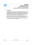
The HT32 Flash Command Protocol is an ASCII-based, challenge-response protocol for firmware
update purposes. It supports up to 7 command sets including obtaining information, erase, blank
check, program/verify, CRC check, execution and read memory. The protocol architecture is
shown in the figure below. The protocol consists of three parts, command with parameter, returned
value and an acknowledgement. The host sends a command to the device which starts with a
1-byte command character, then follows with the optional parameters and ends with a commandend character (CE, 0x0D). Note that each byte received by the device will be sent back to the
host directly for error detection. Once the device has received the command-end character, it will
respond with a 2 byte acknowledge string (ACK, 0x0D 0x0A) to indicate that the command has
been successfully received. The device will then start parsing the command/parameter and proceed
accordingly with the required Flash operation. After the operation has finished, the device sends
the optional information, 1 byte of status (ST) and 2 bytes of acknowledgement to the host. Finally,
the device sends a prompt string such as “ISP>” or “IAP>” to notify that the operation has finished
and is ready to receive the next command. The host will check the ST character to confirm if the
operation was successful. The format of each notation is shown in the figure below.
Command
Acknowledge
Command / Parameter
Host
Device
1 Byte
1 Byte
Variable
1 Byte
Variable
1 Byte
Variable
1 Byte
2 Byte
C
S
P1
S
P2
S
Pn
CE
ACK
\r
\r\n
\r
\r\n
\r
\r\n
Process
Return
Host/Device
…
Ready
Device
Variable
1 Byte
2 Byte
4 Bytes
INFOs
ST
ACK
Prompt
Probing
ISP>
Get Information
i
1
31744
O
\r\n
ISP>
O
\r\n
ISP>
Program / Verify
w
C:
Command
CE:
Command End
S:
Space
ACK: Acknowledge
0x7bff
0xc00
0
Pn:
Parameter n
ST:
Result
INFOs: Return Value
\r:
\n:
0x0D
0x0A
Required
Condition
Xmodem ...
Option
Figure 23. Holtek Flash Programmer Protocol
Rev. 1.00
33 of 49
July 14, 2011
Using the ISP and IAP Firmware
HT32 Flash Command Protocol
32-bit ARM Cortex-M3 MCU
HT32 Series
Command Format
The following table shows the supported command sets for the HT32 Flash Command Protocol.
Detailed information behind each command will be discussed in the following section.
Table 19. Command Description
Command
Description
C
S
Parameter
P1
S
Return
P2
INFOs ST
i
□ [TYPE]
[INFO1] □ [INFO2]…
[INFOn][ST]
Erase
e
□ [TYPE] □ [SADDR]
□ [EADDR]
[ST]
Blank Check
b
□ [SADDR] □ [EADDR]
[ST]
Program or Verify
w
□ [TYPE] □ [SADDR]
□ [EADDR]
[ST]
CRC Check
c
□ [SADDR] □ [EADDR]
[CRC][ST]
Execution, Exit, or Reset
g
□ [TYPE]
None
r
□ [R1] □ [SADDR]
□ [EADDR]
[Byte stream][ST]
Read Memory
: Space (0x20)
Note that the commands, [SADDR] and [EADDR] must be in lowercase letters.
Rev. 1.00
34 of 49
July 14, 2011
Using the ISP and IAP Firmware
Get Information
32-bit ARM Cortex-M3 MCU
HT32 Series
Command Descriptions
▀ Get Information (i)
Table 20. Get Information Command (i)
Descriptions
Get information from device according to the parameter, [TYPE].
Format
Command:i □ [TYPE][CE]
Return: [INFO][ST]
Return
Example
Description
[TYPE]
Information type. See Table 21 for more information.
[INFO]
Returned information. See Table 21 for more information
[ST]
Result
O: Get information is successful
F: [TYPE] is not supported
Descriptions
Host
Device
Get chip name
i□0
HT32F1253O
Get flash size
i□1
31744O
Using the ISP and IAP Firmware
Parameter
Item
Table 21. TYPE Definition of Get Information Command
TYPE
Description
Return
Examples
Unit
0
Get chip name
[INFO][ST]
HT32F1253O
HT32F1251O
Text (ASCII)
1
Get Flash size
[INFO][ST]
31744O
8192O
In bytes (ASCII)
2
Get Option size
[INFO][ST]
1024O
In bytes (ASCII)
3
Get OB_PP bit count
[INFO][ST]
31O
8O
Bit Count (ASCII)
4
Get firmware version
[INFO][ST]
ISPV1.0.0O
IAPV1.0.0O
Text (ASCII)
5
Get firmware date
[INFO][ST]
2011-03-11O
Text (ASCII)
6
Get ISP/IAP start address [INFO][ST]
0O
4096O
8192O
In bytes (ASCII)
Others
Not support
F
State
Rev. 1.00
[ST]
35 of 49
July 14, 2011
32-bit ARM Cortex-M3 MCU
HT32 Series
▀ Mass / Page Erase (e)
Table 22. Mass/Page Erase Command (e)
Descriptions
Apply mass/page erase according to the parameter, [TYPE].
Format
Command:e □ [TYPE] □ [SADDR] □ [EADDR]
Return:
[ST]
Return
Example
Description
[TYPE]
0: Mass erase (Note1)
1: Page erase
[SADDR]
Start address (Note2). Range: 0x0 ~ [EADDR]
[EADDR]
End address (Note2). Range: [SADDR] ~ maximum address of chip
[ST]
Result
O: Erase operation successful
F: Failed erase operation - address out of range or erase type not
supported
Descriptions
Host
Device
Mass erase
e□0
O
Page erase
e □ 1 □ 0x0 □ 0x17ff
O
NOTES: 1. The IAP mode only supports the page erase command. The IAP Firmware returns [ST] = F when it
receives a mass erase command.
2. [SADDR] and [EADDR] are only valid under the page erase mode ([TYPE] = 1).
▀ Blank Check (b)
Table 23. Blank Check Command (b)
Descriptions
Apply blank check in a specific range according to the parameters, [SADDR] and [EADDR].
Format
Command:b □ [SADDR] □ [EADDR]
Return:
[ST]
Parameter
Return
Example
Rev. 1.00
Item
Description
[SADDR]
Start address. Range: 0x0 ~ [EADDR]
[EADDR]
End address. Range: [SADDR] ~ maximum address of chip
[ST]
Result
O: Blank check successful
F: Failed blank check - some Flash content is not equal to 0xFFFFFFFF
Descriptions
Host
Device
Blank check
b □ 0x0 □ 0xffff
O
36 of 49
July 14, 2011
Using the ISP and IAP Firmware
Parameter
Item
32-bit ARM Cortex-M3 MCU
HT32 Series
▀ Program / Verify (w)
Table 24. Program/Verify Command (w)
Descriptions
Start Xmodem protocol for program or verify operation.
Format
Command:w □ [TYPE] □ [SADDR] □ [EADDR]
Return: [ST]
Return
Example
Description
[TYPE]
Program or verify mode
0: Verify mode
1: Program mode
[SADDR]
Start address for program or verify. Range: 0x0 ~ [EADDR]
[EADDR]
End address for over range checking.
Range: [SADDR] ~ maximum address of chip
[ST]
Result
O: Program/Verify successful
F: Failed Program/Verify .
Address out of range/Flash error/Xmodem CRC error…etc.
Descriptions
Host
Device
Program
w □ 0x1 □ 0x0 □ 0x1fff
O
Verify
w □ 0x0 □ 0x0 □ 0x1fff
O
Using the ISP and IAP Firmware
Parameter
Item
▀ CRC Check (c)
Table 25. CRC check (c)
Descriptions
Start CRC check operation according to the parameters, [SADDR] and [EADDR].
Format
Command:c □ [SADDR] □ [EADDR]
Return:
[CRC][ST]
Parameter
Return
Example
Rev. 1.00
Item
Description
[SADDR]
Start address for CRC calculation. Range: 0x0 ~ [EADDR]
[EADDR]
End address for CRC calculation. Range: [SADDR] ~ maximum address
of chip
[CRC]
16 bit CRC value
[ST]
Result
O: CRC calculation successful
Descriptions
Host
Device
CRC check
c □ 0x0 □ 0x1fff
[ByteLByteH]O
37 of 49
July 14, 2011
32-bit ARM Cortex-M3 MCU
HT32 Series
▀ Execution / Exit / Reset (g)
Table 26. Execution, Exit, and Reset Command (g)
Descriptions
Start user application execution, exit ISP/IAP firmware command mode or reset the device.
Format
Command:g □ [TYPE]
Return:
[ST] (Optional)
Description
Parameter
[TYPE]
Execution, Exit, or Reset
0: Execution
1: Exit
2: Reset
Return
[ST]
Result for Execution
F: User application does not exist when [TYPE] = 0
Descriptions
Host
Device
Execution
g□0
F if failed
Exit
g□1
None
Reset
g□2
None
Example
Using the ISP and IAP Firmware
Item
▀ Read Memory (r)
Table 27. Read Memory Command (r)
Descriptions
Read Flash memory content from chip.
Format
Command:r □ [R1] □ [SADDR] □ [EADDR]
Return:
[Byte stream][ST]
Parameter
Return
Example
Rev. 1.00
Item
Description
[R1]
Reserved. Always 0.
[SADDR]
Start address. Range: 0x0 ~ [EADDR]
[EADDR]
End address. Range: [SADDR] ~ maximum address of chip
[ST]
Result
O: Read operation successful
F: Failed read operation - security lock is enabled or address out of range
Descriptions
Host
Device
Read main Flash
r □ 0 □ 0x0 □ 0x1fff
[Byte stream]O
Read option bytes
r □ 0 □ 0x1ff00000 □ 0x1ff00030
[Byte stream]O
38 of 49
July 14, 2011
32-bit ARM Cortex-M3 MCU
HT32 Series
Using the ISP Bootloader
The ISP bootloader is a preloaded program that uses a UART interface to communicate with the
HT32 Flash Programmer through the HT32 Flash Command Protocol. To start the ISP bootloader,
the following items must be noted:
Since the ISP bootloader is located at an independent area, it can erase/program all the device Flash
memory. It also supports the Mass Erase and Security protection functions. If the UART interface
and boot setting is accessible in the end products, the ISP bootloader can be used to update the
application as well as the IAP firmware.
Rev. 1.00
39 of 49
July 14, 2011
Using the ISP and IAP Firmware
▀ Ensure that the boot setting on the target board is set as Bootloader. It should be “BOOT0 = 0,
BOOT1 = 0” or BOOT0 = 0, BOOT1 = 1” according to the device. Refer to the user manual for
each device for more information.
▀ Connect the target board to the COM port of the PC with an RS232 cable.
▀ Start a COM port program such as HyperTerminal or HT32 Flash Programmer
▀ Ensure that the UART is setup as follows:.
● Baud rate: 115200 bps
● Data: 8 bits
● Parity check: None
● Stop bit: 1 bit
● Flow control: None
▀ Turn on the device power. If the connection is correct, a prompt string such as “ISP>” will be
shown in HyperTerminal or a “Connected” message in the HT32 Flash Programmer.
32-bit ARM Cortex-M3 MCU
HT32 Series
IAP Example Code
Introduction
USART
Rx
Tx
UART
Rx Buffer
Tx
FMC
Program
Xmodem
CRC16
Read
IAP Handler
NVIC
Erase
Booting
FLow
Main Routine
IAP Example Code
CKCU
AFIO
Firmware Library
GPIO
Peripheral
Function Call
Firmware Lib.
HW Function
IAP SW
Architecture of IAP Example Code
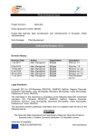
Figure 24. IAP Example Code Architecture
Rev. 1.00
40 of 49
July 14, 2011
Using the ISP and IAP Firmware
This section describes the text mode and UI mode of the IAP example code. Figure 24 shows
the architecture of the IAP example code. The major part of the IAP example code is the “IAP
Handler” module that is responsible for parsing commands and co-working with other modules
to finish all the operations. The “UART Buffer” module uses RAM space with an Rx interrupt
driving routine to store all the data from the host. Using a large RAM buffer and interrupt driving,
data receiving and Flash programming operations can be handled simultaneously to reduce
operation time. “IAP Handler” receives both command and Xmodem packets from the buffer and
uses the Flash Memory Controller to program the data into the Flash memory. Additionally, the
“CRC16” module calculates the CRC value for the Xmodem protocol and Flash checksum.
32-bit ARM Cortex-M3 MCU
HT32 Series
The “Main Routine” manages system initialisation such as Clock, I/O, and interrupts. It also uses
BOOT0 to decide if the user application or the IAP mode should be initiated. The following figure
shows the boot flow of the IAP example code.
IAP Start
BOOT0 = 1
N
(BOOT0 = 0)
Y
Application trigger IAP?
Y
SBVT0 = Magic Number
(0x55AAFAF5)
N
Application
SP and PC valid?
N
Y
IAP Mode
Application
End
Note: Application can set SBVT0 as 0x55AAFAF5 and trigger a reset
to start IAP mode. SBVT registers only reset by Power-on-reset.
Figure 25. IAP mode Boot Flow
Rev. 1.00
41 of 49
July 14, 2011
Using the ISP and IAP Firmware
▀ Enter the IAP mode when IO (BOOT0) is set to 0.
▀ Enter the IAP mode when the application triggers. (Application set SBVT0 to “0x55AAFAF5”
and triggers a reset).
▀ Enter the IAP mode when the application image does not exist - check the application vector
format
▀ Otherwise, start application execution.
32-bit ARM Cortex-M3 MCU
HT32 Series
The IAP example code is a part of the HT32 series firmware library. Obtain the latest version of
the HT32 series firmware library from Holtek’s website or the supplied Holtek CD-ROM. The IAP
example code includes four folders as shown in Figure 26.
“AP_Example” shows how to set the RO address for IAP usage. By default, the RO address will
be set to 0xC00 for the IAP application. The first 3k Bytes is reserved for the IAP. “IAP_Text” and
“IAP_UI” provide an example of the IAP mode using the UART interface. Details regarding the
IAP text mode and the IAP UI mode will be provided in the following sections. Additionally, “IAP_
Text_RAM” provides example code for self updating the IAP firmware.
Rev. 1.00
42 of 49
July 14, 2011
Using the ISP and IAP Firmware
Figure 26. IAP Example Code Folders
32-bit ARM Cortex-M3 MCU
HT32 Series
IAP Text Mode Example Code
The IAP Text mode provides a text menu to download the user's image into the main Flash via the
UART. This example runs on the HT32 series development board. The IAP text mode example
code source files are shown in the table below.
Table 28. Text Mode Source Files
Path
IAP_Text/Src_IAP/
IAP_Text/EWARMv5.4/
IAP_Text/MDK_ARM/
Rev. 1.00
Descriptions
main.c
Main application program
ht32fxxxx_it.c / ht32fxxxx_it.h
Application Interrupt handlers
ht32fxxxx_conf.h
Firmware library configuration file
system_ht32fxxxx.c
System configuration file
iap_main.c
IAP main program
iap_handler.c / iap_handler.h
IAP handler which controls the image update
procedural
iap_xmodem.c / iap_xmodem.h
Xmodem transmission protocol
iap_buffer.c / iap_buffer.h
UART buffer function
iap_crc16.c / iap_crc16.h
Xmodem and Flash checksum CRC algorithm
iap_ht32fxxxx_it.c / iap_ht32fxxxx_it.h
IAP Interrupt handlers
ht32fxxxx_conf.h
Firmware library configuration file of IAP
iap_system_ht32fxxxx.c
IAP system configuration file
Project.eww
EWARM project file
iap_startup_ht32fxxxx.s
EWARM IAP startup file
startup_ht32fxxxx.s
EWARM application startup file
iap_ht32fxxxx_flash.icf
EWARM IAP link script file
ht32fxxxx_flash.icf
EWARM application link script file
Project.uvmpw
MDK-ARM multi-project file
iap_startup_ht32fxxxx.s
MDK-ARM IAP startup file
startup_ht32fxxxx.s
MDK-ARM application startup file
iap.s
ASM file that includes IAP application binary
iap.lin
MDK-ARM link script file
iap.ini
Debug initialisation file
43 of 49
July 14, 2011
Using the ISP and IAP Firmware
IAP_Text/Src_AP/
Filename
32-bit ARM Cortex-M3 MCU
HT32 Series
This example uses a multi-project to manage both the IAP program and the user's application. A
multi-project helps to build/download/debug both the IAP and application at the same time. The
following steps show how to build/download/debug using a multi-project setup.
▀ For Keil uVision
MDK_ARM/HT32Fxxxx_xxx/Obj/IAP_AP.hex
MDK_ARM/HT32Fxxxx_xxx/Obj/IAP_AP.axf.bin/AP
(HEX file for both IAP and application)
(Binary file for application)
Download: Right-click on the project name “Project_AP” in “Project” window and click “Set as
Active Project”. Press the “LOAD” icon to download the IAP and application into the Flash
memory.
Debug: Make sure the active project is “Project_AP”. Press “Ctrl+F5” to enter the debug mode. The
debug symbol of the IAP will be loaded by “iap.ini”. Since both images of the IAP and the
application have been loaded into uVision, trace the program switching behavior between
the IAP and the application.
▀ For IAR EWARM
Build: Double click on “EWARMv5.4/Project.eww” to open the multi-project file. Press “F8”
or tick “Project → Batch Build” to open the “Batch Build” window. Select the “Make”
or “Rebuild All” button to build both the IAP and the application. The output file for the
programming tools are as follows:
EWARMv5.4/HT32Fxxxx_xxx/Exe/IAP_AP.bin
EWARMv5.4/HT32Fxxxx_xxx/Exe/AP.bin
(Binary file for both IAP and application)
(Binary file for application)
Download: Ensure that the active project is “Project_IAP - HT32Fxxxx_xxx” by ticking the dropdown list in the “Workspace” window. Select “Project → Download → Download active
application” to download the IAP and application into the Flash memory.
Debug: Ensure that the active project is “Project_AP - HT32Fxxxx_xxx”. Press “Ctrl+D” to enter
the debug mode. Only the application program can be traced due to the current project
settings.
Rev. 1.00
44 of 49
July 14, 2011
Using the ISP and IAP Firmware
Build: Double click on “MDK_ARM/Project.uvmpw” to open the multi-project file. Select the
“Batch Build” icon on the toolbar, or tick “Project → Batch Build” to open the “Batch
Build” window. Select the “Build” or “Rebuild” button to build both the IAP and the
application. The output file for the programming tools are as follows:
32-bit ARM Cortex-M3 MCU
HT32 Series
After the example code has been downloaded into the target board, open a COM port application
such as HyperTerminal in the PC. Change the UART settings as shown below.
Figure 27. Application Text Menu
If BOOT1 = 1 and BOOT0 = 0 or if Key “1” is selected from the above application menu, then the
IAP mode will be initiated and a text menu will be displayed as shown below. From the screen,
choose the desired function. For example, select “2” to download an image to Flash. This example
follows the Xmodem protocol and sends numerous “C” characters to indicate that it is ready to
receive data from PC. Start the Xmodem transmission and choose a binary file to program into the
application target board.
Figure 28. IAP Text Mode Text Menu
Rev. 1.00
45 of 49
July 14, 2011
Using the ISP and IAP Firmware
▀ Baud rate: 115200 bps
▀ Data: 8 bits
▀ Parity check: None
▀ Stop bit: 1 bit
▀ Flow control: None
Connect the target board to the PC using an RS232 cable and reset the target board. If both BOOT0
and BOOT1 are set to 1, the user application will be initiated and display a text menu via the UART
as shown below. Select a “1” ~ “3” key to execute the corresponding function.
32-bit ARM Cortex-M3 MCU
HT32 Series
IAP UI Mode Example Code
The IAP UI mode is connected with a user interface to download the user's image into the main
Flash via the UART. The interface can be the windows-based HT32 Flash Programmer or any user
application as long as it meets with the HT32 Flash Command Protocol. Refer to Section 3.1 for
more information about the HT32 Flash Command Protocol. The IAP UI mode example source
files are listed in the table below.
Path
IAP_UI/Src_AP/
IAP_UI/Src_IAP/
IAP_UI/EWARMv5.4/
IAP_UI/MDK_ARM/
Filename
Description
main.c
Application main program
ht32fxxxx_it.c / ht32fxxxx_it.h
Application Interrupt handlers
ht32fxxxx_conf.h
Firmware library configuration file
system_ht32fxxxx.c
System configuration file
iap_main.c
IAP main program
iap_handler.c / iap_handler.h
IAP handler which controls the image
update procedural
iap_xmodem.c / iap_xmodem.h
Xmodem transmission protocol
iap_buffer.c / iap_buffer.h
UART buffer function
iap_crc16.c / iap_crc16.h
CRC algorithm for Xmodem and Flash
checksum
iap_ht32fxxxx_it.c / iap_ht32fxxxx_it.h
IAP Interrupt handlers
ht32fxxxx_conf.h
IAP firmware library configuration file
iap_system_ht32fxxxx.c
IAP system configuration file
Project.eww
EWARM project file
iap_startup_ht32fxxxx.s
EWARM IAP startup
startup_ht32fxxxx.s
EWARM application startup file
iap_ht32fxxxx_flash.icf
EWARM IAP link script file
ht32fxxxx_flash.icf
EWARM application link script file
Project.uvmpw
MDK-ARM multi-project file
iap_startup_ht32fxxxx.s
MDK-ARM IAP startup file
startup_ht32fxxxx.s
MDK-ARM application startup file
iap.s
ASM file that includes IAP binary with
application
iap.lin
MDK-ARM link script file
iap_ht32fxxxx.ini
Debug initialisation file
Additionally, this example uses a multi-project to manage both the IAP program and the user's
application. A multi-project helps to build/download/debug both the IAP and the application at the
same time. The following steps show how to build/download/debug using a multi-project setup.
Rev. 1.00
46 of 49
July 14, 2011
Using the ISP and IAP Firmware
Table 29. IAP UI mod Source Files
32-bit ARM Cortex-M3 MCU
HT32 Series
▀ For the Keil uVision
Build: Double click on “MDK_ARM/Project.uvmpw” to open the multi-project file. Select the
“Batch Build” icon on the toolbar, or tick “Project → Batch Build” to open the “Batch
Build” window. Tick the required device name such as “HT32Fxxxx” located in both
"Project_AP" and “Project_IAP”. Select the “Build” or “Rebuild” button to build both the
IAP and the application. The output files for the programming tools are as follows:
MDK_ARM/Obj/IAP_AP_HT32Fxxxx.hex
MDK_ARM/Obj/IAP_AP_HT32Fxxxx.axf.bin/AP
(HEX file of both IAP and application)
(Binary file of application)s
Download: Right-click on the project name “Project_AP” in “Project” window and click on "Set as
Active Project". Select the "LOAD" icon to download the IAP and application into the Flash
memory.
Debug: Ensure that the active project is “Project_AP”. Select “Ctrl+F5” to enter the debug mode.
The IAP debug symbol will be loaded by “iap.ini”. Since both IAP and application images
have been loaded into uVision, trace the program switching behavior between the IAP and
the application.
▀ For the IAR EWARM
Build: Double click on “EWARMv5.4/Project.eww” to open the multi-project file. Press “F8” or
select “Project → Batch Build” to open the “Batch Build” window. Select the required
device name such as “HT32Fxxxx”. Select the “Make” or “Rebuild All” button to build
both the IAP and the application. The programming tools output files are as follows:
EWARMv5.4/HT32Fxxxx/Exe/HT32Fxxxx_IAP_AP.bin
EWARMv5.4/HT32Fxxxx/Exe/HT32Fxxxx_AP.bin
(Binary file of both IAP and application)
(Binary file of application)
Download: Ensure that the active project is “Project_IAP - HT32Fxxxx” by selecting the dropdown list in the “Workspace” window. Select “Project → Download → Download active
application” to download the IAP and the application into the Flash memory.
Debug: Ensure that the active project is “Project_AP - HT32Fxxxx”. Press “Ctrl+D” to enter the
debug mode. Only the application program can be traced due to the current project settings.
In a similar way to the IAP text mode, the boot settings can be changed to start an application
or the IAP mode. The IAP UI mode is designed to connect to the HT32 Flash Programmer or a
customer Flash Programmer that is compatible with the HT32 Flash Command Protocol. Refer to
the relevant chapter for how to use the HT32 Flash Programmer.
Rev. 1.00
47 of 49
July 14, 2011
Using the ISP and IAP Firmware
32-bit ARM Cortex-M3 MCU
HT32 Series
Updating the IAP Firmware
▀ Quick Start Guide: Keil MDK-ARM Quick Start for Holtek’s HT32 Series Microcontrollers
▀ Quick Start Guide: IAR EWARM Quick Start for Holtek’s HT32 Series Microcontrollers
▀ Holtek Programming Environment - HOPE3000 - for 32-Bit MCU User Manual
Additionally, the example code, “IAP_Text_RAM” which will be executed in RAM provides an
alternative solution for updating the IAP firmware itself. This example code uses link script to
specify the load view and execute view of the image’s RO code. The RO code is located at the
beginning of the main Flash and is copied to RAM by the C library before the IAP routine starts.
Since the IAP routine is located in RAM during execution, it can erase and re-program the whole
IAP image in the main Flash. Note that during the download process, the target board must not be
powered off or reset, otherwise the download process will fail and the target will be unable to boot
from the main Flash anymore. In the above situations, it is required to use the ISP, ICP, or Flash
Writer to download the IAP image.
Refer to the “IAP_Text” section to build and download the “IAP_Text_RAM” example code into
the target board. This example code will display a Text menu via the UART as shown below. Here,
for example, press “3” to start Xmodem and update the IAP firmware.
Figure 29. RAM Executed IAP Text Mode Text Menu
Rev. 1.00
48 of 49
July 14, 2011
Using the ISP and IAP Firmware
For the embedded Flash memory system, erase or programming operations must not be applied on
a page where the program is executing. Since the IAP example code is located at the beginning of
the main Flash, it is not possible to update the IAP itself via a general IAP downloading procedural.
In such cases the IAP firmware will disappear if it tries to erase or re-program itself. To program
or update the IAP Firmware, another programming method such as the ISP, the USB debugger, or
Flash Writer is required. For more information about the USB debugger or Flash Writer, refer to the
documents below.
32-bit ARM Cortex-M3 MCU
HT32 Series
Using the ISP and IAP Firmware
Holtek Semiconductor Inc. (Headquarters)
No.3, Creation Rd. II, Science Park, Hsinchu, Taiwan
Tel: 886-3-563-1999
Fax: 886-3-563-1189
http://www.holtek.com.tw
Holtek Semiconductor Inc. (Taipei Sales Office)
4F-2, No. 3-2, YuanQu St., Nankang Software Park, Taipei 115, Taiwan
Tel: 886-2-2655-7070
Fax: 886-2-2655-7373
Fax: 886-2-2655-7383 (International sales hotline)
Holtek Semiconductor Inc. (Shenzhen Sales Office)
5F, Unit A, Productivity Building, No.5 Gaoxin M 2nd Road, Nanshan District, Shenzhen, China 518057
Tel: 86-755-8616-9908, 86-755-8616-9308
Fax: 86-755-8616-9722
Holtek Semiconductor (USA), Inc. (North America Sales Office)
46729 Fremont Blvd., Fremont, CA 94538, USA
Tel: 1-510-252-9880
Fax: 1-510-252-9885
http://www.holtek.com
Copyright© 2011 by HOLTEK SEMICONDUCTOR INC.
The information appearing in this document is believed to be accurate at the time of publication. However,
Holtek assumes no responsibility arising from the use of the specifications described. The applications
mentioned herein are used solely for the purpose of illustration and Holtek makes no warranty or
representation that such applications will be suitable without further modification, nor recommends the use
of its products for application that may present a risk to human life due to malfunction or otherwise. Holtek's
products are not authorized for use as critical components in life support devices or systems. Holtek reserves
the right to alter its products without prior notification. For the most up-to-date information, please visit our
web site at http://www.holtek.com.tw.
Rev. 1.00
49 of 49
July 14, 2011