1
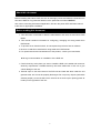
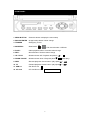
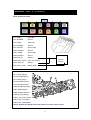
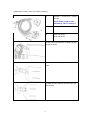
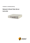
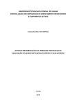
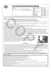
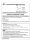
Thank you for purchasing our product.
Please read this User’s Manual before
using the product. Change without Notice
4 / 8 Channel Mobile DVR
User’s Manual
Safety Precautions
CAUTION
RISK OF ELECTRICAL
SHOCK. DO NOT OPEN !
CAUTION: TO REDUCE THE RISK OF ELECTRICAL SHOCK,
DO NOT REMOVE COVE R (OR BACK), NO USER
SERVICEABLE PARTS REFE R SERVICING TO
QUALIFIED SERVICE PERSONNEL.
The lightning flash
triangle, is intended
dangerous Voltage
sufficient magnitude
with arrowhead symbol, within an equilateral
to alert the user to the presence of insulated
within the product’s enclosure that may be
to constitute risk of electrical shock to persons.
The exclamation point within an equilateral triangle is intended to alert
the user to the presence of important operation and maintenance
(servicing) instructions in the literature accompanying the appliance.
WARNING: TO PREVENT FIRE OR SHOCK HAZARD, DO NOT
EXPOSE UNITS NOT SPECIFICALLY DESIGNED FOR
Attention: installation should be performed by qualified service
Personnel only in accordance with the National Electrical Code or
applicable local codes.
Power Disconnect. Units with or without ON-OFF switches have
power supplied to the unit whenever the power cord is inserted into
the power source; however, the unit is operational only when the
ON-OFF switch is the ON position. The power cord is the main power
disconnect for all unites.
Warranty
and Service
There are no serviceable parts for this unit, call for your agent for
details.
2
About this document
Before installing stand alone DVR, be sure to thoroughly review and follow the instructions in
this User’s Manual. Pay particular attention to the parts that are marked NOTICE.
Also, when connecting with external application, first turn the power OFF and follow manual
instruction for appropriate installation.
Before reading this document
1. This document is intended for both the administrator and users of stand alone DVR
Model.
2. This manual contains information for configuring, managing and using stand alone
DVR Model.
3. To prevent fire or electrical shock, do not expose the product to heat or moisture.
4. Be sure to read this manual before using stand alone DVR Model.
5. For questions and technical assistance of this product, contact your local dealer.
►Strong recommendation on installation of the DVR unit
1. Check electricity at the place you want to install the DVR unit is stable and meets our
electricity requirements. Unstable electricity will cause malfunction of the unit or give
critical damage to the unit.
2. Several chips on the main board of the DVR unit and hard disk drive inside the unit
generate heat, and it must be properly discharged. Do not put any objects just beside
exhaust port(fan) on the left side of the unit and do not close up an opening (fresh air
in-take) on the right side of the unit..
3
FCC Statement:
WARNING
This device complies with Part 15 FCC Rules. Operation is subject to the following two
conditions: (1) this device may not cause harmful interference. (2) This device must
accept any interference received including interference that may cause undesired
operation."
* Federal Communications Commission (FCC) Statement
WARNING
This Equipment has been tested and found to comply with the limits for a Class B digital
device, pursuant to Part 15 of the FCC rules. These limits are designed to provide
reasonable protection against harmful interference in a residential installation. This
equipment generates uses and can radiate radio frequency energy and, if not installed
and used in accordance with the instructions, may cause harmful interference to radio
communications. However, there is no guarantee that interference will not occur in a
particular installation. If this equipment does cause harmful interference to radio or
television reception, which can be determined by turning the equipment off and on, the
user is encouraged to try to correct the interference by one or more of the following
measures:
- Reorient or relocate the receiving antenna.
- Increase the separation between the equipment and receiver.
- Connect the equipment into an outlet on a circuit different from
that to which the receiver is connected.
- Consult the dealer or an experienced radio/TV technician for help.
* You are cautioned that changes or modifications not expressly approved by the party
responsible for compliance could void your authority to operate the equipment.
4
FRONT PANEL
1. MENU BUTTON
: Press this button to display the menu setup
2. BACKUP/ENTER : Image backup button / Value change
3. TRIGGER
: Emergency record
4. MODE/ESC
: Quad mode
5. PLAY/+
: Video playback button / Increase values change
6. REC/-
: Record button / Reduce values change
7. UP / STOP
: Direction button UP / Playback stop button
8. DOWN / PAUSE
: Direction button down / Playback pause
9. REW
: Reverse playback choose button / play speed
/
10. FF
: Forward playback choose button / play speed
/
11. USB 2.0
: Pan Driver slot
12. CF Card
: CF Card Driver slot
/ Full channel select / OSD exit
/
5
/
/
(Step play)
REAR PANEL (TYPE A : 4 CH device )
Power and alarm cables
11
9
7
5
3
1
12
10
8
6
4
2
Pin1: RLNC
Relay NC
Pin2: ALARM4
Alarm 4
Pin3: RLNO
Relay NO
Pin4: ALARM3
Alarm 3
Pin5: RLCOM
Alarm COM
PIN6: ALARM2
Alarm 2
PIN7: OGND
Alarm GND
PIN8: ALARM1
Alarm 1
PIN9: BAT_IN
Battery +
PIN10: ACC_Power
ACC_Connection
PIN11: BAT_IN
Battery +
PIN12: BAT_GND
Battery GND
+
-Vehicle
Battery
Pin1: RLNC (White)
Pin2: ALARM4 (Blue)
10
Pin3: RLNO (Gray)
Pin4: ALARM3 (Green)
8
12
11
Pin5: RLCOM (Purple)
9
7
5
PIN6: ALARM2 (Orange)
3
PIN7: OGND (Black)
1
PIN8: ALARM1 (Brown)
2
PIN9: BAT_IN (Yellow)
PIN10: ACC_Power (Red)
6
4
PIN11: BAT_IN (Yellow)
PIN12: BAT_GND (Black)
Notice: System will startup when ACC power connection input is high.
6
REAR PANEL (TYPE B : 8 CH device )
20
19
18
17
16
15
14
13
12
11
10
9
8
7
6
5
4
3
2
1
Pin1
RLNC (Blue)
Relay NC
Pin2
RLNO (Orange)
Relay NO
Pin3
RLCOM (White)
Alarm COM
Pin4
OGND (Black)
Alarm GND
Pin5
OGND (Black)
Alarm GND
PIN6
OGND (Black)
Alarm GND
PIN7
OGND (Black)
Alarm GND
PIN8
OGND (Black)
Alarm GND
PIN9
BAT_GND(Black)
Battery GND
PIN10
ACC_Power (Red)
ACC_Connection
PIN11
ALARM 8 (Green)
Alarm 8
PIN12
ALARM 7 (Brown)
Alarm 7
PIN13
ALARM 6 (Gray)
Alarm 6
PIN14
ALARM 5(Purple)
Alarm 5
PIN15
ALARM 4 (Blue)
Alarm 4
PIN16
ALARM 3 (Green)
Alarm 3
PIN17
ALARM 2 (Orange)
Alarm 2
PIN18
ALARM 1 (Brown)
Alarm 1
PIN19
BAT_IN (Yellow)
Battery +
PIN20
BAT_IN (Yellow)
Battery +
+
-Vehicle
Battery
10
1
7
25 Pin Mini Din Pin definition (Female) :
5
3
6
4
2
1
* TYPE 1 (Standard ):
1. -----
4. GND
2. -----
5. +12V
3. Audio
6. Video
Standard
5
3
6
4
2
* TYPE 2 (Option):
1. GND
4. +12V
2. ------
5. -----
3. Video
6. Audio
1
Option
Y Cable Function :
1. Use the Y Cable , it ensures that only the DVR can supply power to the Camera .
2. The camera can output the video single to DVR and LCD at the same time via the Y Cable .
‚
•
ƒ
•
‚
ƒ
Mini Din : 6 pin Female connector , connect to Camera .
Mini Din : 6 pin Male connector , connect to DVR.
Mini Din : 6 pin Male connector , connect to LCD.
8
Cables define: Video / Audio / IR sensor extending
1.
Camera 1 ~ 4 input (or 1 ~ 8 input)
Mini din
Notice: NTSC or PAL is auto
detected by video in channel 1
ƒ
2.
IR sensor extended line
3.
Video out (RCA)
•
Audio out (RCA)
‚
Please confirm the direction of cable and DVR
D type connector
After direction confirmed, please connect the
cable
To make sure the cable is connect to the rear
side of DVR
9
DVR
Live mode
Playback mode
**Notice**
Please set HDD to Master if only one
installed.
Indicator:
Live:
u.3
Live mode
Video loss
Recording
Overwrite
Motion
Alarm
Relay (Motion / Alarm)
Channel sequence
Keypad lock * 111111 is the default password
* Overwrite (Disk usage with record device)
Playback:
Forward
Reverse
10
Pause
Remote controller:
The key on the remote controller function control is same as the front keypad of the unit.
TRIGGER
Emergency record
SHIFT
Switch the channel button
Ch 1 ~ 4 / ch 5 ~ 8
Number
Channel select 1 ~ 4 / 5 ~ 8
(Need use SHIFT key to switch)
Quad
/
UP / STOP
screen display
Direction button up / Playback
stop button
REW
Reverse playback choose
button
DOWN / PAUSE
Direction button down /
Playback pause
FF
Forward playback choose
button
ENTER
Enter button or value change
AUTO
Full screen auto sequence
MENU
OSD Menu
REC
Start / Stop record
BACKUP
Image backup
ESC
OSD exit
PLAY
Run playback mode
LOCK
To button key lock
AUDIO
Audio page display
+
Increase + values change
-
Reduce - values change
11
Main Menu – Camera Setup
Right adjustment of each element will increase picture quarterly displayed. We recommend
you to adjust each element of cameras and monitor to be connected to the DVR unit.
Main menu – Camera Setup – Display
The function is for channel mask.
Main menu – Camera Setup – Title
Camera title setup function allows 5 characters for each channel.
Select Shift to next page and then Enter to confirm camera title.
12
Main Menu – Record Setup
Device & Frame rate set – Record Device
Record Device – User selectable in different record device
N: Normal Record Device
E: Event Record Device
N:Normal Record
Hard disk(HDD)
CF card (CF)
Normal / Event
-------
Process
E:Event Record
N:E:HDD
The video data always record to hard disk
record
N:E:CF
-------
Normal / Event
The video data always record to CF card
record
N:HDD E:CF
Normal record
Event record
Normally the video records to hard disk, but
it records to CF card if there is any event
happens.
13
Device & Frame rate set - Schedule Record Frame rate
( 4 Channels)
( 8 Channels)
Device & Frame rate set - Motion Record Frame rate
( 4 Channels)
( 8 Channels)
Device & Frame rate set - Alarm Record Frame rate
( 4 Channels)
( 8 Channels)
14
Record Setup:
Pre-record Set
OFF / 1MB/2MB/3MB/4MB/5MB/6MB/7MB/8MB
pre alarm/motion/trigger record
Power off Record
OFF / 1 ~ 30 minutes. DVR starts to record automatically after
vehicles engine power off
Record Quality:
Low / Normal / High (See record time table page 13)
Event Rec Duration
OFF / 5 ~ 30 seconds. Duration time recording after event
(alarm / motion / trigger )
Auto Record
When Auto Record is set to “On”, the DVR will start recording
again after 2 minutes of inactivity after being manually stopped.
Data Retention
OFF / 1 ~ 15 days selectable
Notice: 1. Power off record : User have to think about how much time to record after
the car power off , if power off record parameter(time) set too long , it might
cause the car battery low .
(Default setting is off ) .
2. Pre-Record : Pre-Record frame rate follows the schedule record frame rate .
3. Don’t remove CF card when the system is working , it does not support hot
swap function .
4. Pre-record function can work normally only when normal record function
stop record .
15
Main menu - Record Setup – Schedule Record
Notice:
1. Each channel has own frame rate adjustment of different recording mode.
2. In 24 hours, user can adjust each channel frame rate of different record mode. Such as
schedule, motion detection, and alarm record mode
3. Press “BACKUP/ENTER” button to change different record mode
Record Time Table: 80GB HD
Record Quality: Low. Average: 5 KB;
REC FPS(total)
60
30
15
10
REC Hour
72 hr
148 hr
296 hr
444 hr
Record Quality: Normal. Average 10 KB;
REC FPS(total)
60
30
15
10
REC Hour
36 hr
74 hr
148 hr
222 hr
Record Quality: High. Average 20 KB;
REC FPS(total)
60
30
15
10
REC Hour
18 hr
37 hr
74 hr
111 hr
**Actual recording time is base on live environment. This table is only for reference.**
20 K x 30 (frame rate) x 60 (mins) x 60 (secs) = 2160000 K = 2160 M / hr
2160 M / hr x 24 = 51840000 K = 51840 M = 51.84 G / (1 Day)
16
Main Menu – Alarm Detection & Motion Detection
Alarm 1 + GND / Alarm 2 + GND / Alarm 3 + GND / Alarm 4 + GND
The Alarm Signal type depends upon the Alarm Sensor polarity defined as NO (Normal Open)
or NC (Normal Close).
Notice :
Type A : Support 4 sets Alarm input .
Type B : Support 8 sets Alarm input .
Alarm POP UP: Event channel jumps to full screen when alarm triggered. Quad screen or
9 split screen with the alarm symbol if more than two cameras triggered.
Relay: NO + COM or NC + COM
Alarm Signal type depends on Alarm Sensor polarity define on NO (N/Open) or NC (N/Close)
mode.
NO + COM: Normally, motion relay is NO + COM connector.
Main Menu – Motion Detection – Motion Area
Detected Area
17
Main Menu – Motion Detection – Motion area selection
Direction button Left or Right + ENTER to cancel detection area.
Select start (right-up corner) point and end (left-below corner) point of detect area.
Main Menu – SCREEN: Split border on or off select.
Video Adjustment: Video screen position movement. Use direction button to move.
Main Menu – Audio Setup
- If microphone, audio line in or any how, user please set the audio record mode to on and also
adjust volume input or output to right sound effects.
- Mute means live audio is turn on or quiet.
Notice: Audio input is from Cam1.
18
Main Menu – System Setup – Device ID
Totally,
The device ID could be set 1 ~ 4000 for management.
( 4 CH)
The device ID could be set 1 ~ 255 for management.
( 8 CH)
Main Menu – System Setup – Storage Setup
Please format hard disk before starting
recording
MENU – System Setup – Security Protection – Password Change (Default is 111111)
Menu Protection:
On / Off. User needs to login password
before enter to menu.
Auto Key Lock:
After 5 ~ 120 seconds system automatically
key lock which means before operate DVR
user needs to unlock.
19
Main Menu – System Setup – Time Setup
1. Press ENTER to login to date and time adjust. 2. Use direction left or right button to change
the data. 3. Press ENTER to select date and time.
After time set or daylight mode turns to on, user needs to Apply and confirm. 0 ~ 9 is
repeatable with increase + button, and decrease - button is opposite.
Date Format: YYYY/MM/DD; MM/DD/YYY; DD/MM/YYYY
Main Menu – System Setup – Dwell Time setup (Channel auto sequence mode setup)
On live mode, press auto to start full channel
sequence. Duration time is base on dwell
time 1 ~ 999 seconds.
Main Menu – System Setup – Buzzer Setup
System Buzzer:
OS operating
Key Press Buzzer: Button operating
Alarm Buzzer:
Alarm triggers warning
Motion Buzzer:
Motion detection warning
Video Loss Buzzer: Camera video loss warning
20
Main Menu – System Set – F/W Upgrade
Stop all hard disk working before update, select F/W upgrade and then press ENTER to
search firmware.
1. Searching Firmware
2. Press PLAY upload, press STOP cancel
3. Firmware Reading
4. Firmware uploading
DVR auto reboot after F/W update.
21
Main Menu – System Set – Load Player Software
Stop all hard disk working before load Player Software and then press ENTER
After press ENTER, the system will search software file from USB device.
After the file is detected, the system ask user to press ENTER to load file.
After press ENTER button, the system starts to load file from USB. Users please wait until
“Done” message appears.
Player Software is loaded in hard disk as factory default. Just in case if user change a
new hard disk.
22
Main Menu – Search & Play button:
Please select HDD or CF device before
playback.
Time List search mode & Event List search mode
Use direction button up and down to select date and time section, and then press ENTER to
start to playback. Time list 100 / Event list 200 / (HDD)
Event list record way;
EX:
A motion or an alarm event happens on 10:30 AM,
Record Setup – Pre-record (Pre-Alarm) Set: set to 8 MB .
Record Setup – Event Rec Duration (Post-Alarm): set to 8 MB .
User goes to event list search;
xxxxxxxxxxxx 10:29:55 motion
-
- - - - - -- - -- - -- - -- - - - - - - -
-
- - - - - -- - -- - -- - -- - - - - - - -
-
- - - - - -- - -- - -- - -- - - - - - - -
START: xxxxxx 10:29:55
END: xxxxxx 10:30:05
23
Time Search:
1. Press ENTER to login to date and time adjust.
2. Use direction left or right button to change the data.
3. Press ENTER to select date and time.
4. Press ESC to return to the previous screen and move cursor to Search.
5. Press ENTER to start the searching.
6. Wait until the unit starts to playback.
Playback mode
Forward speed: x 2 / x 3 / x 4
(Direction right button)
Reverse speed: x 8 / x 16 / x 32
(Direction left button)
Press STOP to search list, press ESC to live mode.
24
Backup mode: Before backup, USB pan driver is required. Back up file size can not exceed
3GB, when system reads USB (thumb driver only) device, the system will stop recording about
2 seconds
Mode 1: On live mode, press backup button to file backup page.
Total hard disk data time range
Select start and end time of backup
After select backup time, apply to count
data size. After size appears, press backup
button to USB page.
Notice: When backup to USB , user can press front panel “Play” key to switch from
HDD or CF card backup , it also have a indication show on the left top corner .
After a while, all backup information display on screen, user now can press backup button to
start file backup. Data is writing to USB pan drive, users please wait until backup complete.
Press menu button to quit USB page.
25
Mode 2: In playback mode , Press backup button to select the backup start time , then press
backup button second time means select the backup end time . The system will calculate the
data size , user have to insert the USB device to USB slot then press backup button to start
backup data .
Mode 3: On event list, choose an event record data, and then press backup button.
Pages go to USB page, after data size appears, press backup button to the page
which is same as mode 1
USB compatible( Max. 4G)
ADATA / Transcend / San Disk / Kingston
26
Main Menu – Language: Standard is English / Chinese;
Main Menu – Exit
User needs to save changes if any function value has changed. And then exit menu.
Trigger Record Function :
When user press the front panel Trigger key , it means active “emergency record“ .
It will be saved a event record into event list .
Pre-alarm record frame rate follow schedule record frame rate .
Post-alarm record frame rate follows schedule record frame rate.
27
Player Software
Open file
28
Start to play;
• ‚ ƒ „
… † ‡
ˆ
‰
Š
1
Fast Reverse
6
Play
2
Play Reverse
7
Fast Forward
3
Previous Frame
8
Full Screen (manual switch)
4
Pause
9
Quad Screen
9 split screen
(Only Type B support this function)
5
Next Frame
10
Capture Image
(Default Save to C:\ Capture)
29
HDD readable in PC. Select hard disk and then click OK to start play.
AVI Button: .vvf files export to .avi format
Select export channel(s) and click audio if included.
Browse for the source file
Browse a path for file output
Percentage of the export AVI progress
30
When use the player to play CF card backup file , it offers the Capture function and let user to
capture video session from backup file .
Operation steps :
1. Open the backup file from the CF card .
2. Press Pause key to pause the screen and then click mouse (right key) , it will display menu
then choose the “Capture“ function . ( see below picture )
3. Choose the “Mark In” to set the capture start point .
4. Press play key to start play until user desire video screen .
5. Press pause key and choose the “Mark out” to set the capture end point .
6. Choose the “Export” , then user can export this session of video from backup file .
Notice :
When start to export the video , the computer will be in busy state , user have to wait
until the operation stop 。
31
Specifications
Mobile DVR
Model
4 CH
8 CH
4 CH Inputs
8 CH Inputs
Input
1.0Vp-p, 75ohm unbalanced (mini din Type)
Output
Main monitor (RCA type) x 1
S/N Ratio
More than 40dB
Color
6.7 Million
Monitoring Method
Channel Display
Single / Quad channel
Sequence Display
Available
Screen Quality
Display Rate
Single / Quad / 9 channels
704(H)x 448(V) Active Pixels(NTSC);
704(H) x 544(V) Active Pixels (PAL)
120 fps (NTSC) / 100 fps (PAL)
Recording/ Play Function
Recording (Max) NTSC Max 60 fps(NTSC); Max 50 fps(PAL)
Recording Resolution
704x224(NTSC); 704x272(PAL)
Record Quality
High / Normal / Low
Compressed Picture
Storage: MJPEG
Recording Control
Normal / Schedule / Event
Pre-Alarm Record
8MB
Post-Alarm Record
5 ~ 30 seconds
Playback Mode
Time list / event list / Date & Time search
Backup and Copy
Backup
Event Backup / Video Data backup
Copy
Copy media files via memory flash
Backup file play
Client software to play files
Other Function
Device ID setup
1 ~ 4000 ID setup
1 ~ 255 ID setup
Power off Record
Off / or after 1 ~ 30 minutes power off recording
Operation Mode
Record / Play
Monitoring
Firmware Watchdog
Recovery
Auto-Reboot by Watchdog
Operation Mode
Duplex (Record +Playback )
Control Device
Front key/ Remote controller
Daylight Saving
Supported
32
Language
English / Chinese
Motion Detect
16 x16 grids camera for all channel
Alarm
Alarm in x 4 / Relay out x 1
Video Loss
Camera video loss detection and buzzer warning
Back-Up
USB 2.0
Storage
2.5” HDD x 1
Alarm in x 8 / Relay out x 1
4 GB supported (CF card minimize size need 512 MB )
CF card
Type I support Sandisk, KingSton, A-DATA
Max number of event
list/ Time file list
Event list 200 / Time list 100 (HDD)
Firmware Upgrade
Support USB firmware upgrade
Shock Protection
Support Hardware Shock Protection
Audio Input
RCA x 1 0.5~1.4Vp-p@20kW (mini din)
HDD Record Mode
Full stop / overwrite
Key Lock
Yes
Dwell Time
Programmable with adjustable dwell time. 0 ~ 999 seconds
Real Time clock (RTC) Correct data and time auto adjustment
Remote Control
Support PHILIPS RC5, NEC
Power Supply
+9V DC & +32V DC
Operating Temperature + 5 ºC ~ + 55 ºC
33