1
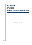
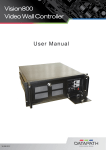
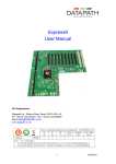
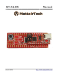
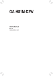
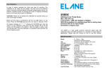
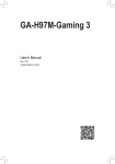
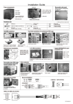
Express11-G3
Backplane
User Guide
Version: 1.02
Unpacking
Your packing box should contain the following items:
•
The Express11-G3 Backplane
•
SLink-G3 Card (optional)
•
HLink-G3 Card (optional)
•
ExCable-G3 (optional)
Installing the Express11-G3 Backplane
The Express11-G3 backplane is fixed into the chassis by screwing down on the mounts located in the host chassis. Ensure the
rear of the Express11-G3 backplane is facing the rear of the chassis.
The chassis will have a number of mount locations not used by the Express11-G3, it is important that mounts are not fitted to
locations which are not utilised by the backplane.
It is expected that when the Express11-G3 backplane is configured as an expansion chassis it will be used with Datapath
HLink-G3 and/or Slink-G3 products in order to benefit from high speed PCIe Gen.3 inter-chassis transfers. In this case no further
configuration of the Express11-G3 is required.
1
Specifications
Express11-G3 Connectors
FAN1,
FAN2,
FAN3
4 pin fan speed control header
Pin 1 : GND
Pin 2 : +12V
Pin 3 : TACH
Pin 4 : PWM
J30,
J31
SATA 2.0
Pin 1 : 0V Pin 2 : A+ Pin 3 : A- Pin 4 : 0V Pin 5 : BPin 6 : B+ Pin 7 : 0V
FAN5,
FAN6,
3 pin fan header (non speed control)
Pin 1 : GND
Pin 2 : +12V
Pin 3 : N/C
J33
2 pin fan header (non speed control)
Pin 1 : GND
Pin 2 : +12V
J17
Panel Power Pushbutton Connector
Pin 1 : PWRBUT
Pin 2 : 0V
J38
USB 2.0
Pin 1 : +5V Pin 2 : +5V
Pin 3 : USB1N Pin 4 : USB0N
Pin 5 : USB1P Pin 6 : USB0P
Pin 7 : 0V Pin 8 : 0V
Pin 9 : N/C Pin10 : N/C
J18
Panel Reset Pushbutton Connector
Pin 1 : SHB_RST
Pin 2 : 0V
J40
JTAG
Pin 1 : TCK Pin 2 : 0V
Pin 3 : TDO Pin 4 : +3V
Pin 5 : TMS Pin 6 : +3V
Pin 7 : N/C Pin 8 : TRST
Pin 9 : TDI Pin10 : 0V
J19
Panel LED Connector
Pin 1 : LED Anode
Pin 2 : LED Cathode
J42
Debug + PLX I2C
Pin 1 : SCL Pin 2 : 0V
Pin 3 : SDA Pin 4 : N/C
Pin 5 : N/C Pin 6 : N/C
Pin 7 : N/C Pin 8 : N/C
Pin 9 : N/C Pin10 : 0V
J23, J24 ATX Power Connector
Pin 1 : +3.3V Pin13 : +3.3V
Pin 2 : +3.3V Pin14 : -12V
Pin 3 : 0V Pin15 : 0V
Pin 4 : +5V Pin16 : PS_ON#
Pin 5 : 0V Pin17 : 0V
Pin 6 : +5V Pin18 : 0V
Pin 7 : 0V Pin19 : 0V
Pin 8 : PWR_ON Pin20 : N/C
Pin 9 : +12V Pin21 : +5V
Pin10: +12V Pin22 : +5V
Pin11 : +12V Pin23 : +5V
Pin12 : +3.3V Pin24 : 0V
J49
PLX Debug Speed Select
Pin 1-2 : All slots Gen 1
Pin 2-3 : All slots Gen 3
J25, J26 AUX Power Connector
Pin 1 : 0V Pin 5 : +12V
Pin 2 : 0V Pin 6 : +12V
Pin 3 : 0V Pin 7 : +12V
Pin 4 : 0V Pin 8 : +12V
J50
GPIO
Pin 1 : GPI Pin 2 : 0V Pin 3 : GPO J29
PLX EEPROM Select
Pin 1-2 : EEPROM A - U13
Pin 2-3 : EEPROM B - U14
2
PCIe Port Width
PICMG
X8
Slot 1
X8
Slot 2
X8
Slot 3
X8
Slot 4
X8
Slot 5
X8
Slot 6
X8
Slot 7
X8
Slot 8
X8
Slot 9
X8
Slot 10
X8
Slot 11
X8
Express11-G3 LED’s
The Express11-G3 has an LED for each PCI Express slot and the PICMG1.3 SBC slot. The LED’s indicate the following:
D1
ON = +12V supply present
D2
ON = +3.3V supply present
D3
ON = +5V supply present
D4
ON = +5V Standby supply present
D5
ON = PICMG link speed = G3, FLASH-FAST = G2, FLASH-SLOW = G1 D6
ON = PCIe Slot 1 link speed = G3, FLASH-FAST = G2, FLASH-SLOW = G1
D7
ON = PCIe Slot 2 link speed = G3, FLASH-FAST = G2, FLASH-SLOW = G1 D8
ON = PCIe Slot 3 link speed = G3, FLASH-FAST = G2, FLASH-SLOW = G1
D9
ON = PCIe Slot 4 link speed = G3, FLASH-FAST = G2, FLASH-SLOW = G1
D10
ON = PCIe Slot 5 link speed = G3, FLASH-FAST = G2, FLASH-SLOW = G1
D11
ON = PCIe Slot 6 link speed = G3, FLASH-FAST = G2, FLASH-SLOW = G1 D12
ON = PCIe Slot 7 link speed = G3, FLASH-FAST = G2, FLASH-SLOW = G1 D13
ON = PCIe Slot 8 link speed = G3, FLASH-FAST = G2, FLASH-SLOW = G1
D14
ON = PCIe Slot 9 link speed = G3, FLASH-FAST = G2, FLASH-SLOW = G1 D15
ON = PCIe Slot10 link speed = G3, FLASH-FAST = G2, FLASH-SLOW = G1 D16
ON = PCIe Slot11 link speed = G3, FLASH-FAST = G2, FLASH-SLOW = G1
D17
ON= PLX Fatal Error
D24
ON = PSU FAULT
No LED’s flashing indicates that lane width has not been established. The LED’s will not flash on slots where no cards are
installed.
3
Power and Environment
Max Power (without SBC)
25W
Power requirements
Max current at +3.3V < 0.5A
Max current at +12V < 0.5A
Max current at +5V <4A
Form Factor
PICMG1.3 Host SBC interface (x8 PCIe)
11 x PCI Express (x8) expansion slots
ATX PSU
2 x 24 pin power connectors
2 x 8 pin AUX power connectors
SATA Ports (2.0)
2 x ports via PICMG1.3 interface
USB Port (2.0)
2 x ports via PICMG1.3 interface
Operating Temperature
0 to 35 deg C/32 to 95 deg F
Storage Temperature
-20 to 70 deg C/-4 to 158 deg F
Relative Humidity
5% to 90% non-condensing
4
Connecting an Expansion Chassis
It is possible to connect a numer of expansion chassis to a host system thereby increasing the number of
PCI Express slots available.
There are two basic types of configuration you can construct using the Express11-G3:
The Star Configuration
Each x8 PCI Express slot in the master chassis (containg the SBC) is populated with an HLink-G3 card. Each HLink-G3 is then
connected to an expansion chassis using and Excable-G3 and SLink-G3 card. This configuration provides a high number of
available PCI Express slots with low latency.
When connecting an expansion chassis to a host machine the HLink-G3 card in the host machine must be installed into the x8
slot. The SLink-G3 card in the expansion should be installed in the PICMG1.3 SBC slot.
Connect the HLinkG3 and SLink-G3 cards using the Ex-Cable-G3 as shown in the illustration below:
5
The HLink-G3 and Slink-G3 cards are factory installed into a system as a pair. When connecting expansion chassis ensure that
the pair labelled Link1 are connected using the ExCable-G3, the pair labelled Link2 are connected together and so on. In the
event that this is not possible, connect the expansion chassis to the host machine and re-install the Datapath Driver Install to
reset the pairings.
SLink-G3
HLink-G3
Connecting the chassis is achieved by installing HLink-G3 and SLink-G3 cards in the host and expansion chassis respectively. Connect the two cards using the ExCable-G3.
6
Datapath Limited
Datapath has a long and very successful history in the computer graphics industry. Datapath has been
designing and supplying high performance, high quality graphics display systems to the world’s largest and most demanding
companies and institutions since 1982. Datapath was one of the founding companies of multi-screen Windows acceleration using single and multi board solutions. Now using the very latest display technology Datapath offers some of the world’s leading
multi screen graphics accelerators for the most demanding applications.
As new technology advances, so we at Datapath improve the performance and functionality of both our hardware and software
to give our customers more. Following a continuous development program, we pride ourselves on our support and responsive
nature towards all our customers and their changing needs. As more sophisticated equipment and techniques become readily
available, so we are there to exploit the power and potential that this technology presents.
Technical Support
Registered users can access our technical support line using, email, and the Support page on the Datapath Web Site, usually
with a response within 24 hours (excluding weekends).
Via Email
Send an email to [email protected] with as much information about your system as possible. To enable a swift response
we need to know the following details:
•
Specification of the PC - including processor speed
•
Operating System
•
Application Software
•
Datapath Hardware / Software
•
The exact nature of the problem - and please be as specific as possible.
Please quote version and revision numbers of hardware and software in use wherever possible.
Copyright Statement
© Datapath Ltd., England, 2014
Datapath Limited claims copyright on this documentation. No part of this documentation may be
reproduced, released, disclosed, stored in any electronic format, or used in whole or in part for any
purpose other than stated herein without the express permission of Datapath Limited.
Whilst every effort is made to ensure that the information contained in this User Manual is correct,
Datapath Limited make no representations or warranties with respect to the contents thereof, and do not accept liability for
any errors or omissions. Datapath reserves the right to change specification without prior notice and cannot assume responsibility for the use made of the information supplied. All registered trademarks used within this documentation are acknowledged by Datapath Limited.
7