1
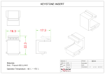
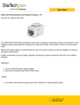
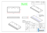
益 震 科 技 股 份 有 限 公 司 Onetouch Technologies Co.,Ltd. Specification of Resistive Controller Board & User Manual Customer : Model : Onetouch-RC-3000 Date : Version: Acceptance Sheet Onetouch Technologies Co., Ltd. (Supplier) Date Onetouch® Approval Signature Model No. (Purchaser) Date Approval Signature Page 1 SPECIFICATION REVISION RECORD Customer : Customer NO.: NO. Version Issue Date : Model : Issue Date Summary of Changes Page <Remarks> Onetouch® Model No. Page 2 Index 1. Outline ………………………………………………………………………………………5 2. General Specification……………………………………………………………………. 5 (1) Supply Voltage and Current ........………………………………………………… 5 (2) Interface……………………………………………………………………………… 5 (3) Operating……………………………………………………………………………. 5 (4) Touch Resolution.……………………………………………………………………..6 (5) Conversion time ………………………...……………………………………………6 (6) Serial Communication Protocol…………………………………………………… 6 (7) Reliability…………………………………………………………………………….. 6 3. Environmental …………………………………………………………………….… (1) Temperature …………………………………………………………..………….… (2) Humidity………………………………………………………………………...…… (3) Shock and Vibration………………………………………………………..….…… (4) ESD ……………………………………………………………………………..…… (5) Flammability………………………………………………………………………… 6 6 6 6 6 6 4. Physical Characterisics…………………………………………………………………. 6 (1) Construction………………………………………………………………………… 6 (2) Dimensions…………………………………………………………………………. 6 5. Connectors and Pin Definitions ….……………………………………………..…….. Onetouch® Model No. Page 7 3 Note ! ! Please avoid using it on the products correlated with the human life. (For example: Medical apparatus, universe apparatus, plane, seafloor relay apparatus,etc. needs high trusting thing) If consider applying to the control of transporting apparatus (train, automobile, boat) or as correlated security, please tell to seller in advance. The quality of this product is used in general products mainly ( Computer, OA machine, FA machine, communication apparatus, measurement apparatus, AV machine,etc. ) * The copyright of this specifications is in Onetouch Technologies Co., Ltd.. All reprint and the reproduction of without permission are prohibited. * The content of this specifications might change without a previous notice. Onetouch® Model No. Page 4 Onetouch Resistive Controller Board Setup and Users Manual This Specifications of Controller is applied for 4/5 wires Resistive Touch ᄃ Name 1. Onetouch-RC-3000: 4 wires +5Wires & USB interface Combo ᄃ Specifications of the Onetouch Touch controller including as following: •Electrical •Environmental •Physical Characteristics •Electrical Supply Voltage and Current Input Voltage +5 VDC, normal (+4.75 to +5.25 VDC). • 16 MA, typical at +5 VDC. Average power consumption (@ stand by mode) is 0.08 W, typical. • Supply must be capable of sourcing 100 MA, minimum. • Total noise and ripple requirement must be less than 100 mV (p-p) for frequencies below 1 MHz, and less than 50 mV (p-p) for frequencies above 1 MHz. Interfac • USB o o HID 1.1 compatible full speed. Support suspend and remote wakeup capability. Operating • Drawing mode • Button mode Touch Resolution • Report 4096x4096, size independent Onetouch® Model No. Page 5 Conversion Time • USB: Max. 250 Points/Sec(pps), typical 200pps Serial Communication Protocol • HID 1.1: Default for USB. Reliability • MTBF greater than 300,000 hours per MIL-HDBK-217-F2 using the parts stress calculationmethod for ground benign environment with an ambient temperature of 25°C Environmental Temperature • Operating: 0°C to 70°C • Storage: -40°C to 85°C Humidity • Operating: 10% to 90% RH, non-condensing • Storage: 10% to 90% RH, non-condensing Shock and Vibration • Three axis sine wave, 50 Hz to 2kHz, 1 G, 2 minutes/Octave with dwell on resonance ESD • Per EN 6100-4-2 1995: Level 4. Contact discharge 8kV, air discharge 15kV. Flammability • The printed circuit board substrate is rated 94V0. All plastic components, such as headers and connectors, are also rated 94V0. Physical Characteristics Construction • Two-layers surface-mount design. Onetouch® Model No. Page 6 Dimensions • Total Width: 20 mm • Total Length: 70 mm(including connector) • Total height: 8.5mm • All mounting holes are plated through for chassis ground connection. Connectors and Pin Definitions • The connector configuration permits the controller to be placed in-line between the touch screen and serial I/O attachments. USB connector, and signal descriptions The serial I/O connector, J1, is a tow-rows by 10-pins header with pins spaced on 2.00mm centers. Refer to the following figure for pin number locations. Figure 1. Pin diagram for USB connector, J1, as viewed from connector mating surfaces Onetouch® Model No. Page 7 Signal definition for USB interface, RC-3000 Signal Name J1 pin SignalFunction D- 5(high) USB bus signal D- D+ 4(high) USB bus signal D+ G 3(high) signal ground V 2(high) +5V power drain from host USB port G 1(high) signal ground Table 1. Host Connector, J1, signal names and functions Onetouch® Model No. Page 8 ※ USB Cable connection(for RC-3000): Onetouch® Model No. Page 9 Touch screen connector, J2(90。 dual row) and signal descriptions The touch screen connector, J2(J3 for Onetouch-RC-3000), is a dual row by five-position header with 0.025-inch square pins spaced on 0.100 centers. 5W sensor must be connected to the upper row of the connector. 4W sensor must be connected to the low row of the connector. The pins are numbered as shown in the figure. Figure 2. Pin diagram for touch screen connector, J2(J3 for AIM-RC-3000), as viewed from connector mating surfaces The 5 Wire Touch screen connector, J2(J3 for Onetouch-RC-3000) upper row, and signal descriptions ※ Note : Pin 5,4,2,1 can be redefinition using autodetect.exe utility software. Signal name J2(J3) pin Signal function LR(Y-) 5 Connect to touch screen Lower Right Conner of glass layer LL(X-) 4 Connect to touch screen Lower Left Conner of glass layer WIPPER 3 Connect to touch screen film layer UR(Y+) 2 Connect to touch screen Upper Right Conner of glass layer UL(X+) 1 Connect to touch screen Upper Left Conner of glass layer Table 2. Touch screen connector, J2(J3) upper row, pins and signal names. The 4 Wire Touch screen connector, J2(J3) lower row, and signal descriptions ※ Note : Pin 4,3,2,1 can be redefinition using autodetect.exe utility software. Signal name J2(J3) pin Signal function None 5 Leave this pin not connect. Y- 4 Connect to 4 Wire touch screen Y- X- 3 Connect to 4 Wire touch screen X- Y+ 2 Connect to 4 Wire touch screen Y+ X+ 1 Connect to 4 Wire touch screen X+ Table 3. Touch screen connector, J2(J3) lower row, pins and signal names Onetouch® Model No. Page 10