1
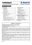
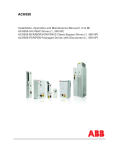
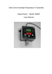
GASGUARDIAN EM3
Entrance Monitor
OPERATING & INSTALLATION MANUAL
GasGuardian EM.
Operating and Installation Manual
Sensor range labels (included with unit)
2
3GasGuardian EM
Operating and Instruction Manual
Table of Contents
General description ………………………………. 4
Installation………………………………….………. 4
Locating the entrance monitor ………......… 4
Installation guidelines………………………… 4
Wiring………………………………………….. 5
Operation ………………………………………….. 8
Sensor range label………………………….. 8
Start-up ……………………………...…………8
Alarm setpoint………………………………… 8
Relay/Alarm test…………………………….... 8
Calibration mode….…………………….….… 8
Oxygen downscale-alarm mode…………… 9
Status LEDs………………………………….. 9
Signal voltage testpoints……………………. 9
Maintenance…………………………….……….. 11
Specifications…………………………………….. 11
Optional power supply………………………….. 12
Warranty………………………………………….. 13
Calibration Technologies
866-394-5861
3
GasGuardian EM.
Operating and Installation Manual
General Description
Powered by 24VDC, the GasGuardian Entrance Monitor
terminates the gas sensor’s 4/20 mA signal, and retransmits the 4/20 mA signal to another analog input
device such as gas detection controller or plant PLC. If
no connection is made to the signal output terminal, the
unit will act as a stand-alone device. Multiple units can
be installed in series, providing flexible remote viewing
options.
The GasGuardian EM is assembled into a wall mounted
enclosure designed for non-classified locations. The
gas sensor (not included) is installed at the location
where gas is to be detected, up to 1,500 feet from the
readout via a three conductor cable.
The GasGuardian EM provides continuous real-time
monitoring of the sensor. Gas concentrations are
indicated by the 10 segment LED bargraph display.
The status LED provides an at-a-glance status of
power, including an alarm or fault condition.
Installation
Locating the GasGuardian EM
The important consideration when installing
GasGuardian EM readout is that it must be easily
accessible for operating personnel.
Installation Guidelines:
• Mount readout on a solid surface with minimal
vibration
• Mount readout in a general-purpose location only.
Do not install in a hazardous environment.
• Mount readout away from electromagnetic
interference.
• Protect readout from physical damage.
A calibration mode setting allows for sensor
maintenance and calibration without tripping the relay.
The onboard relay has a 10 second on/off time delay to
prevent unnecessary cycling during a fault or alarm
condition. The alarm setpoint is adjusted by a ten
position rotary switch on the display board.
An optional add-on power supply is also available to
allow for 120VAC operation.
4
Figure 1: Dimensions
3GasGuardian EM
Operating and Instruction Manual
Wiring
Electrical wiring must comply with all applicable codes.
Wiring Guidelines:
• Always use three conductor, insulated, stranded,
shielded copper cable for all sensor cables.
• Do not pull sensor wiring with AC power cables.
This can cause electrical interference.
• Be sure to land the shield conductors of the sensor
cables at the shield terminals of the sensor
connectors.
• Bonding between metallic conduit connections is
not automatic with the non-conductive enclosure.
Separate bonding must be provided.
DC Power:
• Requires +24VDC, 125 mA (not including other
connected devices)
Sensor Wiring: 4/20 mA, 100 Ohm input impedance.
• Refer to sensor manual for cable
recommendations.
• Typically 20/3 shielded cable (Belden #8772 or
equivalent).
• Length of cable should not exceed 1,500 feet.
Relay Wiring:
• AC wiring must be run in separate conduit from
the sensor cables.
• If a separate relay cable conduit hole is needed,
do not drill or punch hole on hinge side of
enclosure due to close proximity of cable
connectors.
• The alarm relay has Form C dry contacts, and is
rated 10 Amps @ 110 VAC or 24 VDC. (dry
contacts require external power connection)
• The alarm relay is normally energized. It will deenergize to the alarm state upon sensor alarm,
fault or loss of power.
• The alarm relay has a status LED to show the
state of the relay. During normal operation, the
green status LED is on, indicating the relay is
energized.
Stand-Alone and Feed-Through Applications
The GasGuardian EM terminates the gas sensor’s 4/20
mA signal, and re-transmits the 4/20 mA signal to
another analog input device such as gas detection
controller or plant PLC. If no connection is made to the
signal output terminal, the unit will act as a stand-alone
device.
Feed-through application wiring specifications:
• Maximum input impedance: 700 Ohms
• Cable recommendations: 20/3 shielded cable
(Belden #8772 or equivalent).
• Length of cable should not exceed 1,500 feet.
5
GasGuardian EM.
Operating and Installation Manual
Figure 2: Wiring Diagram (Stand-Alone application)
6
3GasGuardian EM
Operating and Instruction Manual
Figure 3: Wiring Diagram (Feed-Through application)
7
GasGuardian EM.
Operating and Installation Manual
Operation
Sensor Range Label
The GasGuardian EM is shipped with various range
labels. If the range of the sensor is not the default
range of 0/100 ppm, select the proper range label and
affix it over the default label.
Start-up
Before applying power, make a final check of all wiring
for continuity, shorts, grounds, etc. It is usually best to
disconnect external alarms and other equipment from
the GasGuardian EM until the initial start-up procedures
are completed.
Refer to sensor manual for proper warm-up time of
sensor prior to any sensor test.
Because sensors are normally located at a distance
from the main unit, the test time required and accuracy
of the response checks will be improved if two people
perform the start-up procedures and use radio contact.
Start-Up Test:
1) One person exposes the sensor to calibration or
test gas.
2) The second person stays at the control unit to
determine that the sensor, when exposed to the
gas, causes appropriate alarm functions.
8
Alarm Setpoint
The GasGuardian EM is has one adjustable alarm
setpoint. The 10-position rotary switch allows for alarm
setpoint adjustments in 10% increments. Once the
sensor signal has exceeded the alarm setpoint, the
alarm LED will light immediately, and the alarm relay will
set after a 10 second time delay. Once the signal has
decreased lower than the alarm setpoint, the relay will
clear after a 10 second time delay.
Relay/Alarm Test
The relay test function allows for testing of the relay
output function without gassing the sensor. To test the
relay, put unit into “calibration mode” (see below), and
turn the 10-position rotary switch to the “0” setting. After
the short time delay, the relay will “set” into the alarm
condition. To “clear” the relay, adjust the setpoint to the
intended alarm position.
Calibration Mode
Calibration mode allows for sensor calibration and
maintenance without causing external alarm conditions.
To activate calibration mode, slide the Cal switch to the
on position. To deactivate, slide switch to off position.
In calibration mode, the following conditions apply:
1. The green power LED will flash twice per
second
2. The relay will remain locked in the clear, nonalarm condition.
3. The analog output will remain locked at 4 mA.
3GasGuardian EM
Operating and Instruction Manual
Oxygen Downscale-Alarm Mode
The oxygen downscale mode provides downscale
alarming for oxygen level monitoring. To activate
downscale alarm mode, slide the O2 switch to the on
position.
Status LED’s
The GasGuardian EM is equipped with the following
status LEDs:
Gas Concentration Bargraph: The 10-segment yellow
LED bargraph will display the gas concentration in 10%
increments. Use the tick-marks on the full-scale range
label to the left of the display to determine the
concentration.
Power: The green power LED will remain on solid to
indicate power
Alarm: The red alarm LED will flash once per second
during an alarm condition.
Fault: The red fault will light and remain on solid in the
event of a sensor fault condition. Since the
GasGuardian EM is constantly monitoring the sensor
signal, any signal below 1 mA will be considered a
sensor fault.
Relay Status: (see page 10 for LED location) The
green relay LED will remain on solid, in the “clear”
position, during normal operation.
Signal Voltage Testpoints
There are two sets of signal testpoints for signal
verification and troubleshooting purposes. These
signals are measured in mVDC, and range from 40 to
200 mV. The SIG IN testpoints indicate the 4/20 mA
signal coming from the sensor. The SIG OUT testpoints
indicate the 4/20 mA signal being re-transmitted to
another control panel or PLC if used as a feed-through
device.
9
GasGuardian EM.
Operating and Installation Manual
Figure 4: Components and Operation
10
3GasGuardian EM
Operating and Instruction Manual
Maintenance
All gas detection systems should be calibrated with
certified calibration gas once every six months. At this
interval, all alarm functions and outputs should be
tested, verified and documented.
If sensor span or zero cannot be adjusted, refer to the
sensor manual. The sensor may be approaching its end
of life and may need to be replaced. Keep an operation
log of all maintenance, calibrations and alarm events.
To clean the controller, use a mild cleaning solution and
soft cloth.
Specifications
Power Requirements: +24 VDC, 125 mA (not including
other connected devices)
Dimensions: 6.2” high x 4” wide x 3” deep
Weight: 1 lb
Enclosure: Injection-molded NEMA 4X polycarbonate
gasketed housing. Hinged lid with (2) latching clasps.
For non-classified areas. Rated for outdoors and
washdown locations. Anodized aluminum mounting
plate.
Temperature Range: -40°F to +122°F
Humidity Range: 0% to 100% condensing
Sensor Inputs: (1) 4/20 mA, 100 Ohm input
impedance
Analog Output:
4/20 mA (max input impedance: 700 Ohms)
Relay Outputs:
(1) SPDT relay, 10A @ 24 VDC or 120 VAC. Dry
contacts
Wiring Connections:
3 conductor, shielded, stranded, 20 AWG cable (Belden
8772 or equivalent) up to 1500 ft (for sensor and analog
output wiring).
Visual Status Indications: (1) Yellow 10-segment LED
bargraph gas concentration display. (1) Green power
LED. (1) Red alarm LED. (1) Red fault LED. (1) Green
relay status LED.
11
GasGuardian EM.
Operating and Installation Manual
Optional Power Supply
The GasGuardian EM is available with an optional AC
to DC power supply, which mounts inside of the
enclosure. This supply can be used for stand-alone
applications where only 120 VAC power is available
and/or external devices (horns, strobes, exhaust fans,
etc.) will be activated via the onboard relay of the
GasGuardian EM.
Order number: GG-EM-PS
Specifications:
Output: 24 VDC, 0.625 A
Overload, short-circuit and thermal protection
Washdown and weatherproof with proper conduit fittings
12
Limited Warranty & Limitation of Liability
Calibration Technologies, Inc. (CTI) warrants this product to be free from defects in material and workmanship under
normal use and service for a period of one year, beginning on the date of shipment to the buyer. This warranty
extends only to the sale of new and unused products to the original buyer. CTI’s warranty obligation is limited, at CTI’s
option, to refund of the purchase price, repair, or replacement of a defective product that is returned to a CTI
authorized service center within the warranty period. In no event shall CTI’s liability hereunder exceed the purchase
price actually paid by the buyer for the Product.
This warranty does not include:
a) routine replacement of parts due to the normal wear and tear of the product arising from use;
b) any product which in CTI’s opinion, has been misused, altered, neglected or damaged by accident or abnormal
conditions of operation, handling or use;
c) any damage or defects attributable to repair of the product by any person other than an authorized dealer or
contractor, or the installation of unapproved parts on the product
The obligations set forth in this warranty are conditional on:
a) proper storage, installation, calibration, use, maintenance and compliance with the product manual instructions
and any other applicable recommendations of CTI;
b) the buyer promptly notifying CTI of any defect and, if required, promptly making the product available for
correction. No goods shall be returned to CTI until receipt by the buyer of shipping instructions from CTI; and
c) the right of CTI to require that the buyer provide proof of purchase such as the original invoice, bill of sale or
packing slip to establish that the product is within the warranty period.
THE BUYER AGREES THAT THIS WARRANTY IS THE BUYER’S SOLE AND EXCLUSIVE REMEDY AND IS IN
LIEU OF ALL OTHER WARRANTIES, EXPRESS OR IMPLIED, INCLUDING BUT NOT LIMITED TO ANY IMPLIED
WARRANTY OF MERCHANTABILITY OR FITNESS FOR A PARTICULAR PURPOSE. CTI SHALL NOT BE LIABLE
FOR ANY SPECIAL, INDIRECT, INCIDENTAL OR CONSEQUENTIAL DAMAGES OR LOSSES, INCLUDING LOSS
OF DATA, WHETHER ARISING FROM BREACH OF WARRANTY OR BASED ON CONTRACT, TORT OR
RELIANCE OR ANY OTHER THEORY.
13
GG-EM 01/2014