1
The information in this User’s Manual has been carefully reviewed and is believed to be accurate.
The vendor assumes no responsibility for any inaccuracies that may be contained in this document,
makes no commitment to update or to keep current the information in this manual, or to notify any
person or organization of the updates. Please Note: For the most up-to-date version of this
manual, please see our web site at www.surveontech.com.
Surveon Technology, Inc. ("Surveon") reserves the right to make changes to the product
described in this manual at any time and without notice. This product, including software, if any,
and documentation may not, in whole or in part, be copied, photocopied, reproduced, translated or
reduced to any medium or machine without prior written consent.
IN NO EVENT WILL SURVEON BE LIABLE FOR DIRECT, INDIRECT, SPECIAL, INCIDENTAL,
SPECULATIVE OR CONSEQUENTIAL DAMAGES ARISING FROM THE USE OR INABILITY TO
USE THIS PRODUCT OR DOCUMENTATION, EVEN IF ADVISED OF THE POSSIBILITY OF
SUCH DAMAGES. IN PARTICULAR, SURVEON SHALL NOT HAVE LIABILITY FOR ANY
HARDWARE, SOFTWARE, OR DATA STORED OR USED WITH THE PRODUCT, INCLUDING THE
COSTS OF REPAIRING, REPLACING, INTEGRATING, INSTALLING OR RECOVERING SUCH
HARDWARE, SOFTWARE, OR DATA.
Any disputes arising between manufacturer and customer shall be governed by the laws of Santa
Clara County in the State of California, USA. The State of California, County of Santa Clara shall
be the exclusive venue for the resolution of any such disputes. Surveon total liability for
all claims will not exceed the price paid for the hardware product.
FCC Statement: This equipment has been tested and found to comply with the limits for a Class
A digital device pursuant to Part 15 of the FCC Rules. These limits are designed to provide
reasonable protection against harmful interference when the equipment is operated in a commercial
environment. This equipment generates, uses, and can radiate radio frequency energy and, if not
installed and used in accordance with the manufacturer’s instruction manual, may cause harmful
interference with radio communications. Operation of this equipment in a residential area is likely
to cause harmful interference, in which case you will be required to correct the interference at your
own expense.
California Best Management Practices Regulations for Perchlorate Materials: This Perchlorate
warning applies only to products containing CR (Manganese Dioxide) Lithium coin cells. “Perchlorate
Material-special handling may apply. See www.dtsc.ca.gov/hazardouswaste/perchlorate”
WARNING: Handling of lead solder materials used in this
product may expose you to lead, a chemical known to
the State of California to cause birth defects and other
reproductive harm.
Unless you request and receive written permission from Surveon Technology Inc., you may not
copy any part of this document.
Information in this document is subject to change without notice. Other products and companies
referred to herein are trademarks or registered trademarks of their respective companies or mark
holders.
Copyright © 2009 by Surveon Technology Inc.
All rights reserved.
Preface
About This Manual
This manual is written for professional system integrators and PC technicians. It provides information for the installation and use of the Surveon NVR2000. Installation and maintainance should be performed by experienced technicians only.
The NVR2000 is a high-end single processor 1U rackmount server housed in a
robust server chassis. The motherboard within supports Core2Duo Series
Processor at system bus speeds of 1333/1066/800 MHz.
Manual Organization
Chapter 1: Introduction
The first chapter provides a checklist of the main components included with the
server system and describes the main features of the motherboard and chassis.
Chapter 2: Server Installation
This chapter describes the steps necessary to install the Surveon NVR2000
into a rack and check out the server configuration prior to powering up the system. If
your server was ordered without the processor and memory components, this chapter will refer you to the appropriate sections of the manual for their installation.
Chapter 3: System Interface
Refer to this chapter for details on the system interface, which includes the functions
and information provided by the control panel on the chassis as well as other LEDs
located throughout the system.
iii
Surveon NVR2000 User’s Manual
Chapter 1 Introduction
1-1. Overview
1-2. Motherboard Features
1-3. Contacting Surveon
1-1
1-2
1-3
Chapter 2 Server Installation
2-1. Overview
2-2. Unpacking the System
2-3. Preparing for Setup
2-4. Installing the System into a Rack
2-5. Checking the Motherboard Setup
2-6. Checking the Drive Bay Setup
2-1
2-1
2-1
2-4
2-8
2-9
Chapter 3 System Interface
3-1. Overview
3-2. Control Panel Buttons
3-3. Control Panel LEDs
3-4. SATA Drive Carrier LEDs
3-1
3-1
3-2
3-3
Chapter 4 System Safety
4-1. Electrical Safety Precautions
4-2. General Safety Precautions
4-3. ESD Precautions
4-4. Operating Precautions
4-1
4-2
4-3
4-4
Chapter 5 Advanced Serverboard Setup
5-1. Handling the Serverboard
5-2. I/O Ports
5-3. Installing Memory
5-4. Adding PCI Expansion Cards
5-5. Connector Definitions
5-6. Jumper Settings
5-7. Onboard Indicators
5-1
5-3
5-4
5-5
5-6
5-11
5-13
Chapter 6 Advanced Chassis Setup
6-1. Static-sensitive Devices
6-2. Control Panel
6-3. System Fans
6-4. Drive Bay Install/Removal
6-5. Power Supply
6-1
6-2
6-3
6-3
6-6
Appendix A BIOS POST codes
Appendix B System Specifications
Chapter 1
Introduction
1-1
Overview
The Surveon NVR2000 is a high-end single processor, 1U rack-mount server with
state-of-the-art features. The NVR2000 is comprised of two main subsystems:
the 1U chassis and the motherboard. Please refer to our web site for information
on operating systems that have been certified for use with the NVR2000.
In addition to the mainboard and chassis, various hardware components may have
been included with the NVR2000, as listed below.
One CPU heatsink
Three (3) 4-cm fans (FAN-0061L)
One (1) air shroud
Serial ATA (SATA) Accessories:
One (1) internal SATA backplane (BPN-SAS-815TQ)
One (1) set of SATA cables
One (1) SGPIO cable (CBL-0157L)
Four (4) SATA drive carriers [CSE-PT39 (B)]
Rackmount hardware with screws
One (1) CD containing drivers and utilities
Surveon NVR2000 User's Manual
Surveon NVR2000 User's Manual
1-2
Motherboard Features
At the heart of the Surveon NVR2000 lies the motherboard, a single processor
version based upon Intel's E3210 chipset. Below are the main features of
the motherboard.
Processor
The motherboard supports single Intel Core2Duo Series LGA775 processors at
system bus speeds of 1333, 1066 and 800 MHz. Please refer to the motherboard
specifications pages on our web site for updates on supported processors.
Memory
The motherboard has four 240-pin DIMM slots that comes embedded with 2 GB of
unbuffered ECC DDR2-800/667 SDRAM.
Onboard SATA
A SATA controller provides connectivity to 4 SATA disk drives.
PCI Expansion Slots
The PCI-Express x8 slot can receive an optional SAS HBA for connecting to external
RAID enclosures is extra storage space is required.
Onboard Controllers/Ports
An onboard IDE controller supports one floppy drive and up to two Ultra ATA 100
hard drives or ATAPI devices. Onboard I/O backpanel ports include one COM port,
a VGA port, two USB ports, PS/2 mouse and keyboard ports and two Gigabit LAN
(NIC) ports.
Other Features
Other onboard features that promote system health include voltage monitors, a
chassis intrusion header, auto-switching voltage regulators, chassis and CPU
overheat sensors, virus protection and BIOS rescue.
1-2
Chapter 1: Introduction
1-3
Contacting Surveon
Headquarters
Address:
Surveon Technology Inc.
2F-4, no. 102, Sec. 3, Jhongshan Rd.,
Jhonghe City, Taipei County, 235, Taiwan
Tel:
+886-2-2226-2966
Fax:
+886-2-2226-7128
Email:
[email protected] (General Information)
[email protected] (Technical Support)
Web Site:
www.surveontech.com
1-3
Chapter 2: Server Installation
Chapter 2
Server Installation
2-1
Overview
This chapter provides a quick setup checklist to get your Superveon NVR2000
up and running. Following the steps in the order given should enable you to have
the system operational within a minimal amount of time. This quick setup assumes
that your system has come to you with the processor and memory preinstalled. If your system is not already fully integrated with a motherboard, processor,
system memory etc., please turn to the chapter or section noted in each step for
details on installing specific components.
2-2
Unpacking the System
You should inspect the box the Surveon NVR2000 was shipped in and note
if it was damaged in any way. If the server itself shows damage, you should file a
damage claim with the carrier who delivered it.
Decide on a suitable location for the rack unit that will hold the chassis.
It should be situated in a clean, dust-free area that is well ventilated. Avoid
areas where heat, electrical noise and electromagnetic fields are generated. You
will also need it placed near a grounded power outlet. Read the Rack and Server
Precautions in the next section.
2-3
Preparing for Setup
The box the Surveon NVR2000 was shipped in should include two sets of
rail assemblies, six rail mounting brackets and the mounting screws you will need
to install the system into the rack. Follow the steps in the order given to complete
the installation process in a minimal amount of time. Please read this section in
its entirety before you begin the installation procedure outlined in the sections that
follow.
Choosing a Setup Location
•
Leave enough clearance in front of the rack to enable you to open the front door
completely (~25 inches) and approximately 30 inches of clearance in the back
of the rack to allow for sufficient airflow and ease in servicing.This product is for
2-1
Surveon NVR2000 User's Manual
installation only in a Restricted Access Location (dedicated equipment rooms,
service closets and the like).
•
This product is not suitable for use with visual display work place devices
acccording to §2 of the the German Ordinance for Work with Visual Display
Units.
!
Warnings and Precautions!
!
Rack Precautions
•
•
•
•
Ensure that the leveling jacks on the bottom of the rack are fully extended to
the floor with the full weight of the rack resting on them.
In single rack installation, stabilizers should be attached to the rack. In multiple
rack installations, the racks should be coupled together.
Always make sure the rack is stable before extending a component from the
rack.
You should extend only one component at a time - extending two or more simultaneously may cause the rack to become unstable.
Server Precautions
•
•
•
•
•
•
Review the electrical and general safety precautions in Chapter 4.
Determine the placement of each component in the rack before you install the
rails.
Install the heaviest server components on the bottom of the rack first, and then
work up.
Use a regulating uninterruptible power supply (UPS) to protect the server from
power surges, voltage spikes and to keep your system operating in case of a
power failure.
Allow the hot plug SATA drives and power supply modules to cool before touching them.
Always keep the rack's front door and all panels and components on the servers
closed when not servicing to maintain proper cooling.
2-2
Chapter 2: Server Installation
Rack Mounting Considerations
Ambient Operating Temperature
If installed in a closed or multi-unit rack assembly, the ambient operating temperature of the rack environment may be greater than the ambient temperature of the
room. Therefore, consideration should be given to installing the equipment in an
environment compatible with the manufacturer’s maximum rated ambient temperature (Tmra).
Reduced Airflow
Equipment should be mounted into a rack so that the amount of airflow required
for safe operation is not compromised.
Mechanical Loading
Equipment should be mounted into a rack so that a hazardous condition does not
arise due to uneven mechanical loading.
Circuit Overloading
Consideration should be given to the connection of the equipment to the power
supply circuitry and the effect that any possible overloading of circuits might have
on overcurrent protection and power supply wiring. Appropriate consideration of
equipment nameplate ratings should be used when addressing this concern.
Reliable Ground
A reliable ground must be maintained at all times. To ensure this, the rack itself
should be grounded. Particular attention should be given to power supply connections other than the direct connections to the branch circuit (i.e. the use of power
strips, etc.).
2-3
Surveon NVR2000 User's Manual
2-4
Installing the System into a Rack
This section provides information on installing the Surveon NVR2000 into a
rack unit with the rack rails provided. If the server has already been mounted into
a rack, you can skip ahead to other sections.
There are a variety of rack units on the market, which may mean the assembly
procedure will differ slightly. You should also refer to the installation instructions that
came with the rack unit you are using.
Identifying the Sections of the Rack Rails
You may have received rack rail hardware with the Surveon NVR2000. (Two
front inner rails should already be attached to the chassis.) This hardware consists
of two rear inner rails that secure to the chassis, one on each side just behind the
preinstalled front inner rails. Note that these two rails are left/right specific.
Installing the Rear Inner Rails
First, locate the right rear inner rail (the rail that will be used on the right side of
the chassis when you face the front of the chassis). Align the two square holes on
the rail against the hooks on the right side of the chassis. Securely attach the rail
to the chassis with M4 flat head screws. Repeat these steps to install the left rear
inner rail to the left side of the chassis (see Figure 2-1). You will also need to attach
the rail brackets when installing into a telco rack.
Locking Tabs: Both chassis rails have a locking tab, which serves two functions.
The first is to lock the server into place when installed and pushed fully into the
rack, which is its normal position. Secondly, these tabs also lock the server in place
when fully extended from the rack. This prevents the server from coming completely
out of the rack when you pull it out for servicing.
2-4
Chapter 2: Server Installation
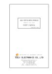
Figure 2-1. Installing Rear Inner Chassis Rails
Installing the Rack Rails
Determine where you want to place the Surveon NVR2000 in the rack (see
Rack and Server Precautions in Section 2-3). Position the chassis rail guides at the
desired location in the rack, keeping the sliding rail guide facing the inside of the
rack. Screw the assembly securely to the rack using the brackets provided. Attach
the other assembly to the other side of the rack, making sure that both are at the
exact same height and with the rail guides facing inward.
2-5
Surveon NVR2000 User's Manual
Installing the Server into the Rack
You should now have rails attached to both the chassis and the rack unit. The next
step is to install the server into the rack. Do this by lining up the rear of the chassis
rails with the front of the rack rails. Slide the chassis rails into the rack rails, keeping
the pressure even on both sides (you may have to depress the locking tabs when
inserting). See Figure 2-2.
When the server has been pushed completely into the rack, you should hear the
locking tabs "click".
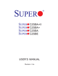
Figure 2-2. Installing the Server into a Rack
2-6
Chapter 2: Server Installation
Installing the Server into a Telco Rack
To install the chassis into a Telco type rack, use two L-shaped brackets on
either side of the chassis (four total). First, determine how far the server
will extend out the front of the rack. Larger chassis should be positioned to balance
the weight between front and back. If a bezel is included on your server, remove
it. Then attach the two front brackets to each side of the chassis, then the two rear
brackets positioned with just enough space to accommodate the width of the rack.
Finish by sliding the chassis into the rack and tightening the brackets to the rack.
Figure 2-3. Installing the Server into a Telco Rack
2-7
Surveon NVR2000 User's Manual
2-5
Checking the Motherboard Setup
After you install the system in the rack, you will need to open the unit to make
sure the motherboard is properly installed and all the connections have been
made.
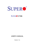
Accessing the Inside of the System
1. Grasp the two handles on either side and pull the unit straight out until it
locks (you will hear a "click").
2. Depress the two buttons on the top of the chassis to release the top cover.
There is a large rectangular recess in the middle front of the top cover to help
you push the cover away from you until it stops.
3. Lift the top cover from the chassis to gain full access to the inside of the
server. See Figure 2-4.
Checking the Components
1. You may have the processor already installed into the system board. The
processor should have its own heatsink attached. See Chapter 5 for instructions on processor installation.
2. Your server system may have come with system memory already
installed. Make sure all DIMMs are fully seated in their slots. For details on
adding system memory, refer to Chapter 5.
3. If desired, you can install an add-on card to the system. See Chapter 5 for
details on installing a PCI add-on card.
4. Make sure all power and data cables are properly connected and not blocking
the airflow. See Chapter 5 for details on cable connections.
2-8
Chapter 2: Server Installation
Figure 2-4.
Accessing the Inside of the Chassis
2-6
Checking the Drive Bay Setup
Next, you should check to make sure the peripheral drives and the SATA drives
and SATA backplane have been properly installed and all essential connections
have been made.
Checking the Drives
All drives can be accessed from the front of the server. The SATA
disk drives can be installed and removed from the front of the chassis without
removing the top chassis cover.ve
Depending upon your system's configuration, your system may have one or
more SATA drives already installed. If you need to install SATA drives, please
refer to the appropriate section in Chapter 6.
Checking the Airflow
Airflow is provided by thee high-performance 4-cm input fans. The system
component layout was carefully designed to promote sufficient airflow through
the small 1U rackmount space
2-9
Surveon NVR2000 User's Manual
2. Also note that all power and data cables have been routed in such a way that
they do not block the airflow generated by the fans.
Providing Power
1. Plug the power cord from the power supply unit into a high-quality power strip
that offers protection from electrical noise and power surges. It is recommended that you use an uninterruptible power supply (UPS).
2. Depress the power button on the front of the chassis to power up the system.
2-10
Chapter 3: System Interface
Chapter 3
System Interface
3-1
Overview
There are several LEDs on the control panel as well as others on the SATA drive
carriers to keep you constantly informed of the overall status of the system as well
as the activity and health of specific components. There are also two buttons on
the chassis control panel and an on/off switch on the power supply. This chapter
explains the meanings of all LED indicators and the appropriate response you may
need to take.
3-2
Control Panel Buttons
There are two push-buttons located on the front of the chassis: a reset button and
a power on/off button.
Reset
The reset switch reboots the system.
Power
This is the main power switch, which is used to apply or turn off the main system
power. Turning off system power with this button removes the main power but
keeps standby power supplied to the system.
3-1
Surveon NVR2000 User's Manual
3-3
Control Panel LEDs
The control panel located on the front of the chassis has five
LEDs. These LEDs provide you with critical information related to different parts of
the system. This section explains what each LED indicates when illuminated and
any corrective action you may need to take.
Overheat/Fan Fail
When this LED flashes, it indicates a fan failure. When on continuously it indicates
an overheat condition, which may be caused by cables obstructing the airflow in
the system or the ambient room temperature being too warm. Check the routing of
the cables and make sure all fans are present and operating normally. You should
also check to make sure that the chassis covers are installed. Finally, verify that
the heatsinks are installed properly (see Chapter 5). This LED will remain flashing
or on as long as the indicated condition exists.
2
NIC2
Indicates network activity on LAN2 when flashing.
1
NIC1
Indicates network activity on LAN1 when flashing.
HDD
Channel activity for all HDDs. This light indicates SATA drive activity
on the NVR2000 when flashing.
3-2
Chapter 3: System Interface
Power
Indicates power is being supplied to the system's power supply units. This LED
should normally be illuminated when the system is operating.
3-4
SATA Drive Carrier LEDs
Each SATA drive carrier has two LEDs.
•
•
Green: When illuminated, the green LED on the front of the SATA drive carrier
indicates drive activity. A connection to the SATA backplane enables this LED
to blink on and off when that particular drive is being accessed.
Red: The red LED indicates two states. When blinking, it indicates the drive
is rebuilding. When solid, it indicates a drive failure. If a SATA drive fails, you
should be notified by your system management software. Please refer to Chapter
6 for instructions on replacing failed SATA drives.
3-3
Surveon NVR2000 User's Manual
Notes
3-4
Chapter 4: System Safety
Chapter 4
System Safety
4-1
Electrical Safety Precautions
!
Basic electrical safety precautions should be followed to protect yourself from harm
and the Surveon NVR2000 from damage:
•
•
•
•
•
•
•
Be aware of the locations of the power on/off switch on the chassis as well
as the room's emergency power-off switch, disconnection switch or electrical
outlet. If an electrical accident occurs, you can then quickly remove power from
the system.
Do not work alone when working with high voltage components.
Power should always be disconnected from the system when removing or installing main system components, such as the serverboard, memory modules
and floppy drive. When disconnecting power, you should first power down the
system with the operating system first and then unplug the power cords of all
the power supply units in the system.
When working around exposed electrical circuits, another person who is familiar
with the power-off controls should be nearby to switch off the power if necessary.
Use only one hand when working with powered-on electrical equipment. This
is to avoid making a complete circuit, which will cause electrical shock. Use
extreme caution when using metal tools, which can easily damage any electrical
components or circuit boards they come into contact with.
Do not use mats designed to decrease static electrical discharge as protection
from electrical shock. Instead, use rubber mats that have been specifically
designed as electrical insulators.
The power supply power cords must include a grounding plug and must be
plugged into grounded electrical outlets.
4-1
Surveon NVR2000 User's Manual
•
Serverboard Battery: CAUTION - There is a danger of explosion if the onboard
battery is installed upside down, which will reverse its polarites (see Figure
4-1). This battery must be replaced only with the same or an equivalent type
recommended by the manufacturer. Dispose of used batteries according to the
manufacturer's instructions.
•
Mainboard replaceable soldered-in fuses: Self-resetting PTC (Positive Temperature Coefficient) fuses on the mainboard must be replaced by trained service
technicians only. The new fuse must be the same or equivalent as the one
replaced. Contact technical support for details and support.
4-2
General Safety Precautions
!
Follow these rules to ensure general safety:
•
Keep the area around the NVR2000 clean and free of clutter.
•
The NVR system weighs approximately 38 lbs (~17.3 kg) when fully loaded.
When lifting the system, two people at either end should lift slowly with their
feet spread out to distribute the weight. Always keep your back straight and lift
with your legs.
•
•
•
Place the chassis top cover and any system components that have been removed away from the system or on a table so that they won't accidentally be
stepped on.
While working on the system, do not wear loose clothing such as neckties and
unbuttoned shirt sleeves, which can come into contact with electrical circuits or
be pulled into a cooling fan.
Remove any jewelry or metal objects from your body, which are excellent metal
conductors that can create short circuits and harm you if they come into contact
with printed circuit boards or areas where power is present.
4-2
Chapter 4: System Safety
•
After accessing the inside of the system, close the system back up and secure
it to the rack unit with the retention screws after ensuring that all connections
have been made.
4-3
ESD Precautions
!
Electrostatic discharge (ESD) is generated by two objects with different electrical
charges coming into contact with each other. An electrical discharge is created to
neutralize this difference, which can damage electronic components and printed
circuit boards. The following measures are generally sufficient to neutralize this
difference before contact is made to protect your equipment from ESD:
•
•
•
•
•
•
•
•
Use a grounded wrist strap designed to prevent static discharge.
Keep all components and printed circuit boards (PCBs) in their antistatic bags
until ready for use.
Touch a grounded metal object before removing the board from the antistatic
bag.
Do not let components or PCBs come into contact with your clothing, which may
retain a charge even if you are wearing a wrist strap.
Handle a board by its edges only; do not touch its components, peripheral chips,
memory modules or contacts.
When handling chips or modules, avoid touching their pins.
Put the serverboard and peripherals back into their antistatic bags when not
in use.
For grounding purposes, make sure your computer chassis provides excellent
conductivity between the power supply, the case, the mounting fasteners and
the serverboard.
4-3
Surveon NVR2000 User's Manual
4-4
Operating Precautions
!
Care must be taken to assure that the chassis cover is in place when the NVR2000
is operating to assure proper cooling. Out of warranty damage to the system can
occur if this practice is not strictly followed.
Figure 4-1. Installing the Onboard Battery
LITHIUM BATTERY
LITHIUM BATTERY
OR
BATTERY HOLDER
BATTERY HOLDER
4-4
Chapter 5: Advanced Serverboard Setup
Chapter 5
Advanced Serverboard Setup
This chapter covers the steps required to install the serverboard into the chassis, connect the data and power cables and install add-on cards. Some serverboard
jumpers and connections are also described. Others should be left at their defaults.
A layout and quick reference chart are included in this chapter for your reference.
Remember to completely close the chassis when you have finished working with
the serverboard to better cool and protect the system.
5-1
Handling the Serverboard
Electrostatic discharge (ESD) can damage electronic components. To prevent damage to any printed circuit boards (PCBs), it is important to handle them very carefully
(see previous chapter). To prevent the serverboard from bending, keep one hand
under the center of the board to support it when handling. The following measures
are generally sufficient to protect your equipment from electric static discharge.
Precautions
•
•
•
•
•
•
Use a grounded wrist strap designed to prevent Electrostatic Discharge
(ESD).
Touch a grounded metal object before removing any board from its antistatic
bag.
Handle a board by its edges only; do not touch its components, peripheral chips,
memory modules or gold contacts.
When handling chips or modules, avoid touching their pins.
Put the serverboard, add-on cards and peripherals back into their antistatic
bags when not in use.
For grounding purposes, make sure your computer chassis provides excellent
conductivity between the power supply, the case, the mounting fasteners and
the serverboard.
5-1
Surveon NVR2000 User's Manual
Unpacking
The serverboard is shipped in antistatic packaging to avoid electrical static discharge. When unpacking the board, make sure the person handling it is static
protected.
5-2
5-2
I/O Ports
The I/O ports are color coded in conformance with the PC 99 specification. See
Figure 5-2 below for the colors and locations of the various I/O ports.
Figure 5-2. I/O Ports
Mouse (Green)
USB0/1 Ports
LAN1/2 Ports
Keyboard
(Purple)
COM1 Port
(Turquoise)
VGA Port
(Blue)
5-3
Surveon NVR2000 User's Manual
5-3
Installing Memory
CAUTION! Exercise extreme care when installing or removing DIMM
!
modules to prevent any possible damage.
Memory Support
The motherboard supports dual or single channel, ECC/Non-ECC unbuffered DDR2800/667 SDRAM. Both interleaved and non-interleaved memory are supported,
so you may populate any number of DIMM slots. (Populating DIMM#1A/DIMM#2A
and/or DIMM#1B/DIMM#2B with memory modules of the same size and type will
result in two-way interleaved memory, which is faster than single channel, noninterleaved memory.) Note that when ECC memory is used, it may take 25-40
seconds for the VGA to display.)
Installing Memory Modules
1. Insert each DDR2 memory module vertically into its slot, starting with DIMM
#1A. Pay attention to the notch along the bottom of the module to prevent
inserting the module incorrectly.
2. Gently press down on the DIMM module until it snaps into place in the slot.
Repeat for all modules. (See support information below.)
3. To enhance memory performance, install pairs of memory modules of the
same type and of the same, beginning with DIMM #1A and DIMM #2A, then
DIMM #1B and DIMM #2B.
Notes
Due to a chipset limitation, 8GB of memory can only be supported by the following
operating systems:
•
•
32-Bit: Windows 2000 Advanced Server, Windows Server 2003 Enterprise Edition;
64-Bit: Windows Server 2003 Standard x64 Edition, Windows XP Professional
x64 Edition, Windows Server 2003 Enterprise x64 Edition
Some old-versions of DDR2-667 may not match Intel's On-Die Temperature requirement and will automatically be downgraded to run at 533 MHz. If this occurs, contact
your memory vendor to check the ODT value.
Due to memory allocation to system devices, memory remaining available for
operational use will be reduced when 4 GB of RAM is used. The reduction in
memory availability is disproportional. (Refer to the Memory Availability Table
below for details.)
5-4
Figure 5-3. DIMM Installation
To Install: Insert module vertically and press
down until it snaps into
place. Pay attention to
the bottom notches.
DDR2
5-4
To Remove: Use your
thumbs to gently push
each release tab outward to free the DIMM
from the slot.
Adding PCI Expansion Cards
The chassis can accommodate one full-size PCI-Express
expansion card with the use of a riser card.
Installing an Add-on Card
1. After powering down the system, remove the PCI slot shield.
2. Fully seat the riser card into the slot, pushing down with your thumbs evenly
on both sides of the card. Seat the expansion card into the riser card.
3. Finish by using a screw to secure the top of the card shield to the chassis.
The PCI slot shield protects the serverboard and its components from EMI
and aid in proper ventilation, so make sure it is always in place.
-
Surveon NVR2000 User's Manual
5-5
Connector Definitions
ATX Power 24-pin Connector
Pin Definitions (JPW1)
Pin#
Definition
Main ATX Power Supply
Connector
13
+3.3V
1
+3.3V
14
-12V
2
+3.3V
The primary power supply connector
15
COM
3
COM
(JPW1) meets the SSI (Superset ATX)
24-pin specification. Refer to the table
16
PS_ON
4
+5V
17
COM
5
COM
on the right for the pin definitions of
18
COM
6
+5V
the ATX 24-pin power connector. You
19
COM
7
COM
20
Res (NC)
8
PWR_OK
21
+5V
9
5VSB
22
+5V
10
+12V
23
+5V
11
+12V
24
COM
12
+3.3V
must also connect the 8-pin (JPW2/
JPW3) processor power connectors to
your power supply (see below).
Secondary Power Connector
Pin #
Definition
+12V 4-pin Power
Pin Definitions (JPW2)
JPW2 must also be connected to the
power supply. See the table on the
right for pin definitions.
Pins
Definition
1-4
Ground
5-8
+12V
Required Connection
PW_ON Connector
The PW_ON connector is on pins 1
and 2 of JF1. This header should be
connected to the chassis power button. See the table on the right for pin
definitions.
Power Button
Pin Definitions (JF1)
Pin#
Definition
1
PW_ON
2
Ground
Reset Connector
The reset connector is located on pins
3 and 4 of JF1 and attaches to the
reset switch on the computer chassis. See the table on the right for pin
definitions.
Power Fail LED
The Power Fail LED connection is
located on pins 5 and 6 of JF1. Refer to the table on the right for pin
definitions.
5-6
Reset Button
Pin Definitions (JF1)
Pin#
Definition
3
Reset
4
Ground
PWR Fail LED
Pin Definitions (JF1)
Pin#
Definition
5
Vcc
6
Ground
Chapter 5: Advanced Serverboard Setup
Overheat/Fan Fail LED (OH)
Connect an LED to the OH connection
on pins 7 and 8 of JF1 to provide advanced warning of chassis overheating. Refer to the table on the right for
OH/Fan Fail LED
Pin Definitions (JF1)
OH/Fan Fail Indicator
Status
Pin#
Definition
State
7
Vcc
Off
Normal
8
Ground
On
Overheat
Flashing
Fan Fail
pin definitions.
Definition
NIC2 (JLAN2) LED
The LED connections for JLAN2 are
on pins 9 and 10 of JF1. Attach an
LED cable to display network activity. See the table on the right for pin
definitions.
NIC2 LED
Pin Definitions (JF1)
Pin#
Definition
9
Vcc
10
Ground
NIC1 (JLAN1) LED
The LED connections for JLAN1 are
on pins 11 and 12 of JF1. Attach an
LED cable to display network activity. See the table on the right for pin
definitions.
NIC1 LED
Pin Definitions (JF1)
Pin#
Definition
11
Vcc
12
Ground
HDD LED
The HDD LED connection is located
on pins 13 and 14 of JF1. This LED
is used to display all IDE and SATA
activity. See the table on the right for
pin definitions.
Power On LED
The Power On LED connector is located on pins 15 and 16 of JF1 (use
JLED for a 3-pin connector). This
connection is used to provide LED
indication of power being supplied to
the system. See the table on the right
for pin definitions.
5-7
HDD LED
Pin Definitions (JF1)
Pin#
Definition
13
Vcc
14
HD Active
Power LED
Pin Definitions (JF1)
Pin#
Definition
15
5V Stby
16
Control
Surveon NVR2000 User's Manual
NMI Button
NMI Button
Pin Definitions (JF1)
The non-maskable interrupt button
header is located on pins 19 and 20
Pin#
Definition
of JF1. Refer to the table on the right
for pin definitions.
19
Control
20
Ground
Fan Headers
There are six fan headers on the
serverboard, all of which are 4-pin
fans. However, pins 1-3 of the fan
Fan Header
Pin Definitions
(FAN1-8)
headers are backward compatible
with the traditional 3-pin fans. See
the table on the right for pin definitions. The onboard fan speeds are
controlled by Thermal Management
(via Hardware Monitoring) under the
Advanced Section in the BIOS. The
default is disabled. When using Thermal Management setting, please use
all 3-pin fans or all 4-pin fans.
Pin#
Definition
1
Ground (Black)
2
+12V (Red)
3
Tachometer
4
PWM Control
Note: Fan 6 is the header for
the CPU heat sink fan.
PS/2 Keyboard and
Mouse Port Pin
Definitions (J28)
ATX PS/2 Keyboard and PS/2
Mouse Ports
The ATX PS/2 keyboard and the PS/2
mouse are located beside the USB0/1
ports. The mouse port is above the
keyboard port. See the table on the
right for pin definitions.
Pin#
Definition
1
Data
2
NC
3
Ground
4
VCC
5
Clock
6
NC
Serial Port Pin Definitions
(COM1/COM2)
Serial Ports
Two serial ports are included on the
serverboard. COM1 is a backpanel
port and COM2 is a header located
beside the printer port. See the table
on the right for pin definitions.
5-8
Pin #
Definition
Pin #
Definition
1
DCD
6
DSR
2
RXD
7
RTS
3
TXD
8
CTS
4
DTR
9
RI
5
Ground
10
NC
Chapter 5: Advanced Serverboard Setup
Chassis Intrusion
Chassis Intrusion
Pin Definitions (JL1)
The Chassis Intrusion header is designated JL1. Attach an appropriate
Pin#
Definition
cable from the chassis to inform you
1
Intrusion Input
of a chassis intrusion when the chas-
2
Ground
sis is opened
Wake-On-LAN
Wake-On-LAN
Pin Definitions
(JWOL)
The Wake-On-LAN header is designated JWOL on the serverboard. See
the table on the right for pin definitions. You must also have a LAN card
with a Wake-On-LAN connector and
cable to use this feature.
Pin#
Definition
1
+5V Standby
2
Ground
3
Wake-up
Wake-On-Ring
The Wake-On-Ring header is designated JWOR. This function allows your
computer to receive and be "awakened" by an incoming call when in the
suspend state. See the table on the
right for pin definitions. You must also
have a WOR card and cable to use
this feature.
Wake-On-Ring
Pin Definitions
(JWOR)
Pin#
Definition
1
Ground (Black)
2
Wake-up
External Speaker/Internal
Buzzer
On the JD1 header, pins 1-4 are for an
external speaker and pins 3-4 are for the
internal speaker. If you wish to use an external speaker, connect it to pins 1-4 to. If
you wish to use the onboard speaker, you
should close pins 3-4 with a jumper.
LAN1/2 (Ethernet Ports)
Two Ethernet ports (designated LAN1
and LAN2) are located beside the VGA
port on the I/O backplane. These ports
accept RJ45 type cables.
5-9
Speaker Connector
(JD1)
Pin Setting
Definition
Pins 3-4
Internal Speaker
Pins 1-4
External Speaker
Surveon NVR2000 User's Manual
Universal Serial Bus (USB)
Universal Serial Bus
Pin Definitions (USB)
There are two Universal Serial Bus
ports located on the I/O panel and four
USB0/1/10/11
Pin #
Definition
additional USB headers located on
1
+5V
1
+5V
the serverboard. The headers can be
2
PO-
2
PO-
3
PO+
3
PO+
4
Ground
4
Ground
5
N/A
5
Key
used to provide front side USB access
(cables not included). See the table on
the right for pin definitions.
USB6/7/8/9
Pin #
Definition
SGPIO Header
Pin Definitions (T-SGPIO-1/T-SGPIO-2)
SGPIO Headers
The SGPIO (Serial General Purpose
Input/Output) headers are used to
communicate with a system-monitoring chip on the backplane. See the
table on the right for pin definitions.
Pin#
Definition
Pin
Definition
1
NC
2
NC
3
Ground
4
DATA Out
5
Load
6
Ground
7
Clock
8
NC
NC = No Connection
Power SMB Header
Pin Definitions (PW4)
Power SMBUS Header
A Power SMB header is located at
SMBUS_PS. Connect the appropriate cable here to utilize SMB on your
system. See the table on the right for
pin definitions.
Pin#
Definition
1
Clock
2
Data
3
PWR Fail
4
Ground
5
+3.3V
Overheat LED/Fan Fail (JOH1)
The JOH1 header is used to connect
an LED to provide warning of chassis
overheating. This LED will blink to indicate a fan failure. Refer to the table
on right for pin definitions.
OH/Fan Fail LED
States
Overheat LED
Pin Definitions (JOH1)
State
Message
Pin#
Definition
Solid
Overheat
1
5vDC
Blinking
Fan Fail
2
OH Active
5-10
Chapter 5: Advanced Serverboard Setup
5-6 Jumper Settings
Explanation of Jumpers
To modify the operation of the
serverboard, jumpers can be used
to choose between optional settings.
3
2
1
3
2
1
Connector
Pins
Jumpers create shorts between two
pins to change the function of the connector. Pin 1 is identified with a square
Jumper
solder pad on the printed circuit board.
See the serverboard layout pages for
jumper locations.
Setting
Note: On a two-pin jumper, "Closed"
means the jumper is on both pins and
"Open" means the jumper is either on
only one pin or completely removed.
CMOS Clear
JBT1 is used to clear CMOS (which will also clear any passwords). Instead of pins,
this jumper consists of contact pads to prevent accidentally clearing the contents
of CMOS.
To clear CMOS,
1. First power down the system and unplug the power cord(s).
2. With the power disconnected, short the CMOS pads with a metal object such
as a small screwdriver.
3. Remove the screwdriver (or shorting device).
4. Reconnect the power cord(s) and power on the system.
Note: Do not use the PW_ON connector to clear CMOS.
VGA Enable/Disable
JPG1 allows you to enable or disable
the VGA port. The default position is on
pins 1 and 2 to enable VGA. See the
table on the right for jumper settings.
5-11
VGA Enable/Disable
Jumper Settings (JPG1)
Jumper Setting
Definition
Pins 1-2
Enabled
Pins 2-3
Disabled
Surveon NVR2000 User's Manual
LAN1/2 Enable/Disable
Change the setting of jumper JPL1
and JPL2 to enable or disable the
LAN1 and LAN2 Ethernets ports, respectively. See the table on the right
for jumper settings. The default setting
LAN1/2 En/Disable Jumper Settings (JPL1/JPL2)
Jumper Setting
Definition
Pins 1-2
Enabled
Pins 2-3
Disabled
is enabled.
Watch Dog Enable/Disable
JWD controls the Watch Dog function.
Watch Dog is a system monitor that
can reboot the system when a software
application hangs. Jumping pins 1-2
will cause WD to reset the system if an
application hangs. Jumping pins 2-3
will generate a non-maskable interrupt
signal for the application that hangs.
See the table on the right for jumper
settings. Watch Dog must also be enabled in BIOS.
Watch Dog
Jumper Settings (JWD)
Jumper Setting
Definition
Pins 1-2
Reset
Pins 2-3
NMI
Open
Disabled
Note: When enabled, the user needs to
write their own application software in
order to disable the Watch Dog Timer.
USB Wake-Up
These jumpers allow you to wake up the
system by pressing a key on the USB
keyboard or by clicking the USB mouse
of your system. The JPUSB jumpers are
used together with the USB Wake-Up
feature in BIOS and both must be enabled to use this feature. See the table
on the right for jumper settings. Notes:
JPUSB1 is for the USB0/1 ports and
JPUSB2 is for USB6/7/8/9/10/11.
Default settings are enabled for JPUSB1
and disabled for JPUSB2. Please be
sure to remove all other USB devices
from the USB ports whose USB jumpers
are set to Disabled before the system
goes into standby mode.
5-12
USB Wake-Up
Jumper Settings
Jumper Setting
Definition
Pins 1-2
Enabled
Pins 2-3
Disabled
Chapter 5: Advanced Serverboard Setup
SMBus to PCI-X/PCI-Exp. Slots
Jumpers JI2C1 and JI2C2 allow you to
SMBus to PCI-X/PCI-E Slots
Jumper Settings (JI2C1/JI2C2)
connect the System Management Bus
(I 2 C) to the PCI-X/PCI-E slots. The
Jumper Setting
Definition
default setting is Open (Disabled.) Both
JI2C1: Closed
JI2C2:Closed
Enabled
jumpers must be set to the same setting
See the table on the right for jumper
JI2C1: Open
JI2C2: Open
Disabled
settings.
5-7 Onboard Indicators
GLAN1/2 LED
(Connection Speed Indicator)
LAN1/2 LEDs
The Ethernet ports (located beside
the VGA port) have two LEDs. On
each port, one LED indicates activity
while the other LED may be green,
amber or off to indicate the speed of
the connection. See the table on the
right for the functions associated with
the connection speed LED.
LED Color
Definition
Off
10 MHz
Green
100 MHz
Amber
1 GHz
Onboard Power LED (LE1)
An Onboard Power LED is located at
LE1. This LED Indicator is lit when
the system is on. Be sure to unplug
the power cable before removing or
adding any components. See the table
on the right for more details.
5-13
Onboard Power LED Indicator
(LE1)
LED Color
Definition
Off
System Off
Green
System on
Chapter 6: Advanced Chassis Setup
Chapter 6
Advanced Chassis Setup
This chapter covers the steps required to install components and perform maintenance on the chassis. For component installation, follow the
steps in the order given to eliminate the most common problems encountered. If
some steps are unnecessary, skip ahead to the step that follows.
Tools Required: The only tool you will need to install components and perform
maintainance is a Philips screwdriver.
6-1
Static-Sensitive Devices
Electrostatic Discharge (ESD) can damage electronic components. To prevent
damage to any printed circuit boards (PCBs), it is important to handle them very
carefully. The following measures are generally sufficient to protect your equipment
from ESD discharge.
Precautions
•
•
•
•
•
•
Use a grounded wrist strap designed to prevent static discharge.
Touch a grounded metal object before removing any board from its antistatic
bag.
Handle a board by its edges only; do not touch its components, peripheral chips,
memory modules or gold contacts.
When handling chips or modules, avoid touching their pins.
Put the motherboard, add-on cards and peripherals back into their antistatic
bags when not in use.
For grounding purposes, make sure your computer chassis provides excellent
conductivity between the power supply, the case, the mounting fasteners and
the motherboard.
Unpacking
The motherboard is shipped in antistatic packaging to avoid static damage. When
unpacking the board, make sure the person handling it is static protected.
6-1
Surveon NVR2000 User's Manual
Figure 6-1. Chassis Front View
Figure 6-2. Chassis Rear View
6-2
Control Panel
The control panel (located on the front of the chassis) must be connected to the
JF1 connector on the motherboard to provide you with system control buttons and
status indicators. These wires have been bundled together in a ribbon cable to
simplify the connection.
The LEDs inform you of system status. See Chapter 3 for details on the LEDs and
the control panel buttons. Details on JF1 can be found in Chapter 5.
6-2
Chapter 6: Advanced Chassis Setup
6-3
System Fans
4-cm high-performance fans provide the cooling for the server. The chassis
includes air seals under the fans and at the chassis cross section,
which separates the drive bay area from the motherboard area of the chassis to
promote better airflow. It is highly important that the air seal is properly installed
and making a good seal in order for the cooling air to circulate properly through
the chassis.
The fans can adjust their speed according to the heat level sensed in the system,
which results in more efficient and quieter fan operation. Fan speed is controlled
by a setting in BIOS.
System Fan Failure
If a fan fails, you will need to have it replaced with the same type. Contact your
vendor or Surveon for information on replacement fans.
6-3
Use caution when working around the SATA backplane. Do not touch
the backplane with any metal objects and make sure no ribbon cables
!
touch the backplane. Also, regardless of how many SATA drives are
installed, all four drive carriers must remain in the chassis to maintain
proper airflow.
6-4. Accessing the Drive Bays
SATA Drives: Because of their tray swap design, you do not need to access the
inside of the chassis or power down the system to install or replace SATA drives.
Proceed to the next step for instructions. Serial ATA Drive Installation
Mounting a Serial ATA Drive in a Drive Carrier
The SATA drives are mounted in drive carriers to simplify their installation and
removal from the chassis. These carriers also help promote proper airflow for the
system. For this reason, even empty carriers without drives installed must remain
in the chassis.
F
1. Install a new SATA drive into the carrier with the printed circuit board side facing down so that the mounting holes align with those in the carrier.
2. Secure the drive to the carrier with six screws, as shown in Figure 6-4.
Chapter 6: Advanced Chassis Setup
1.
Installing/Removing SATA Drives
2. To remove a carrier, push the release button located beside the drive LEDs.
Swing the colored handle fully out and use it to pull the unit straight out (see
Figure 6-5).
Note: Your operating system must have RAID support to enable the hot-plug capability of the SATA drives.
Serial ATA Backplane
The Serial ATA drives plug into a backplane that provides power, drive ID and bus
termination.
Figure 6-5. Removing a SATA Drive from the Server
6-5
Chapter 6: Advanced Chassis Setup
6-5
Power Supply
The Surveon NVR2000 has a single 300 watt power supply. This power supply
has the capability of operating at 100 - 240 input volts. Depress the main power
button on the front of the chassis and then unplug the AC power cord to completely
remove power from the system before removing the power supply.
Power Supply Failure
If the power supply unit fails, the system will shut down and you will need to replace
the power supply unit. Replacement units can be ordered directly from Surveon
(PWS-0054 - see contact infomation in Chapter 1).
Replacing the Power Supply
To replace a power supply, you must first remove the top chassis cover. Follow the
procedure on the previous page.
1. First unplug the power cord from the system.
2. To remove the failed power unit, remove the two screws on the back of the
power supply, which secure it to the chassis. You can then lift the unit straight
out of the chassis.
3. Replace the failed unit with another unit of the same wattage. It is highly
recommended to replace it with the exact same power supply.
4. Carefully insert the new unit into position in the chassis and secure it with the
two screws at the rear of the unit.
5. Before reconnecting the power cord, make sure the power switch on the
power supply is in the off position. Then reconnect the power cord, replace
the chassis top cover and push the unit back into the rack.
6. Finish by turning the power switch on the power supply on, and then depress
the power button on the front of the system.
6-6
Appendix: BIOS POST Codes
Appendix A
BIOS POST Codes
This section lists the POST (Power On Self Test) codes for the Phoenix BIOS. POST
codes are divided into two categories: recoverable and terminal.
Recoverable POST Errors
When a recoverable type of error occurs during POST, the BIOS will display an
POST code that describes the problem. The BIOS may also issue one of the following beep codes:
1 long and two short beeps - video configuration error
1 continuous long beep - overheat (Overheat LED will be on)
1 long beep and 1 short pause - memory not detected
Terminal POST Errors
If a terminal type of error occurs, the BIOS will shut down the system. Before
doing so, BIOS will write the error to port 80h, attempt to initialize video and write
the error in the top left corner of the screen.
The following is a list of codes that may be written to port 80h.
POST Code
02h
03h
04h
06h
07h
08h
09h
0Ah
0Bh
0Ch
0Eh
0Fh
10h
11h
12h
13h
14h
16h
17h
Description
Verify Real Mode
Disable Non-Maskable Interrupt (NMI)
Get CPU type
Initialize system hardware
Disable shadow and execute code from the ROM.
Initialize chipset with initial POST values
Set IN POST flag
Initialize CPU registers
Enable CPU cache
Initialize caches to initial POST values
Initialize I/O component
Initialize the local bus IDE
Initialize Power Management
Load alternate registers with initial POST values
Restore CPU control word during warm boot
Initialize PCI Bus Mastering devices
Initialize keyboard controller
1-2-2-3 BIOS ROM checksum
Initialize cache before memory Auto size
A-1
Surveon NVR2000 User's Manual
POST Code
18h
Description
8254 timer initialization
1Ah
8237 DMA controller initialization
1Ch
Reset Programmable Interrupt Controller
20h
1-3-1-1 Test DRAM refresh
22h
1-3-1-3 Test 8742 Keyboard Controller
24h
Set ES segment register to 4 GB
28h
29h
Auto size DRAM
Initialize POST Memory Manager
2Ah
Clear 512 kB base RAM
2Ch
1-3-4-1 RAM failure on address line xxxx*
2Eh
1-3-4-3 RAM failure on data bits xxxx* of low byte of
memory bus
Enable cache before system BIOS shadow
Test CPU bus-clock frequency
Initialize Phoenix Dispatch Manager
Warm start shut down
Shadow system BIOS ROM
Auto size cache
Advanced configuration of chipset registers
Load alternate registers with CMOS values
Initialize extended memory for RomPilot
Initialize interrupt vectors
POST device initialization
2-1-2-3 Check ROM copyright notice
Initialize I20 support
Check video configuration against CMOS
Initialize PCI bus and devices
Initialize all video adapters in system
QuietBoot start (optional)
Shadow video BIOS ROM
Display BIOS copyright notice
Initialize MultiBoot
Display CPU type and speed
Initialize EISA board
Test keyboard
Set key click if enabled
Enable USB devices
2-2-3-1 Test for unexpected interrupts
Initialize POST display service
Display prompt “Press F2 to enter SETUP”
Disable CPU cache
2Fh
32h
33h
36h
38h
3Ah
3Ch
3Dh
41h
42h
45h
46h
47h
48h
49h
4Ah
4Bh
4Ch
4Eh
4Fh
50h
51h
52h
54h
55h
58h
59h
5Ah
5Bh
A-2
Appendix: BIOS POST Codes
POST Code
Description
5Ch
Test RAM between 512 and 640 kB
60h
62h
Test extended memory
Test extended memory address lines
64h
Jump to UserPatch1
66h
Configure advanced cache registers
67h
Initialize Multi Processor APIC
68h
69h
Enable external and CPU caches
Setup System Management Mode (SMM) area
6Ah
Display external L2 cache size
6Bh
Load custom defaults (optional)
6Ch
6Eh
70h
72h
76h
7Ch
7Dh
7Eh
80h
81h
82h
83h
84h
85h
86h
87h
Display shadow-area message
Display possible high address for UMB recovery
Display error messages
Check for configuration errors
Check for keyboard errors
Set up hardware interrupt vectors
Initialize Intelligent System Monitoring
Initialize coprocessor if present
Disable onboard Super I/O ports and IRQs
Late POST device initialization
Detect and install external RS232 ports
Configure non-MCD IDE controllers
Detect and install external parallel ports
Initialize PC-compatible PnP ISA devices
Re-initialize onboard I/O ports.
Configure Motherboard Configurable Devices
(optional)
Initialize BIOS Data Area
Enable Non-Maskable Interrupts (NMIs)
Initialize Extended BIOS Data Area
Test and initialize PS/2 mouse
Initialize floppy controller
Determine number of ATA drives (optional)
Initialize hard-disk controllers
Initialize local-bus hard-disk controllers
Jump to UserPatch2
Build MPTABLE for multi-processor boards
Install CD ROM for boot
Clear huge ES segment register
Fix up Multi Processor table
1-2 Search for option ROMs. One long, two short
beeps on checksum failure
88h
89h
8Ah
8Bh
8Ch
8Fh
90h
91h
92h
93h
95h
96h
97h
98h
A-3
Surveon NVR2000 User's Manual
POST Code
99h
Description
Check for SMART Drive (optional)
9Ah
9Ch
Shadow option ROMs
Set up Power Management
9Dh
Initialize security engine (optional)
9Eh
Enable hardware interrupts
9Fh
Determine number of ATA and SCSI drives
A0h
A2h
Set time of day
Check key lock
A4h
Initialize typematic rate
A8h
Erase F2 prompt
AAh
ACh
AEh
B0h
B1h
B2h
B4h
B5h
B6h
B7h
B9h
BAh
BBh
BCh
BDh
BEh
BFh
C0h
C1h
C2h
C3h
C4h
C5h
C6h
C7h
C8h
C9h
CAh
CBh
Scan for F2 key stroke
Enter SETUP
Clear Boot flag
Check for errors
Inform RomPilot about the end of POST.
POST done - prepare to boot operating system
1 One short beep before boot
Terminate QuietBoot (optional)
Check password (optional)
Initialize ACPI BIOS
Prepare Boot
Initialize SMBIOS
Initialize PnP Option ROMs
Clear parity checkers
Display MultiBoot menu
Clear screen (optional)
Check virus and backup reminders
Try to boot with INT 19
Initialize POST Error Manager (PEM)
Initialize error logging
Initialize error display function
Initialize system error handler
PnPnd dual CMOS (optional)
Initialize Note dock (optional)
Initialize Note dock late
Force check (optional)
Extended checksum (optional)
Redirect Int 15h to enable remote keyboard
Redirect Int 13h to Memory Technologies
Devices such as ROM, RAM, PCMCIA, and serial disk
Redirect Int 10h to enable remote serial video
CCh
A-4
Appendix B: BIOS POST Codes
POST Code
Description
CDh
Re-map I/O and memory for PCMCIA
CEh
D2h
Initialize digitizer and display message
Unknown interrupt
The following are for boot block in Flash ROM
POST Code
Description
E0h
Initialize the chipset
E1h
Initialize the bridge
E2h
E3h
Initialize the CPU
Initialize system timer
E4h
E5h
E6h
E7h
E8h
E9h
EAh
EBh
ECh
EDh
EEh
EFh
F0h
F1h
F2h
F3h
F4h
F5h
F6h
F7h
Initialize system I/O
Check force recovery boot
Checksum BIOS ROM
Go to BIOS
Set Huge Segment
Initialize Multi Processor
Initialize OEM special code
Initialize PIC and DMA
Initialize Memory type
Initialize Memory size
Shadow Boot Block
System memory test
Initialize interrupt vectors
Initialize Run Time Clock
Initialize video
Initialize System Management Manager
Output one beep
Clear Huge Segment
Boot to Mini DOS
Boot to Full DOS
If the BIOS detects errors on 2C, 2E, or 30 (base 512K RAM error), it displays an
additional word-bitmap (xxxx) indicating the address line or bits that have failed. For
example, “2C 0002” means address line 1 (bit one set) has failed. “2E 1020" means
data bits 12 and 5 (bits 12 and 5 set) have failed in the lower 16 bits. The BIOS also
sends the bitmap to the port-80 LED display. It first displays the checkpoint code,
followed by a delay, the high-order byte, another delay, and then the loworder byte of
the error. It repeats this sequence continuously.
A-5
Surveon NVR2000 User's Manual
Notes
A-6
Appendix: System Specifications
Appendix B
System Specifications
Processors
Single Core2Duo Series LGA775 processors at system bus speeds
of 1333, 1066 and 800 MHz
Note: Please refer to the motherboard specifications pages on our web site for updates on supported
processors.
Chipset
Intel 3210/ICH9R chipset
BIOS
16 Mb Phoenix® Flash ROM
Memory Capacity
Four 240-pin DIMM slots that can support up to 8 GB of unbuffered ECC
DDR2-800/667 SDRAM
Note: See the memory section in Chapter 5 for details.
SATA Controller
On-chip (ICH9R) 3 Gb/s Intel SATA controller
SATA Drive Bays
Four (4) drive bays to house four standard SATA drives
PCI Expansion Slots
One PCI-E x8 slot (with riser card: CSE-RR1U-ELi)
Motherboard
Form Factor: ATX
Dimensions: 12 x 9.6 in (305 x 244 mm)
B-1
Surveon NVR2000 User's Manual
Chassis
1U Rackmount
Dimensions: (WxHxD) 17.2 x 1.7 x 19.85 in. (437 x 43 x 504 mm)
Note: please visit our web site for information on supported operating systems
Weight
Gross Weight: 38 lbs. (17.3 kg.)
System Cooling
Three (3) 4-cm high performance fans
System Input Requirements
AC Input Voltage: 100-240V AC auto-range
Rated Input Current: 5A max
Rated Input Frequency: 50 to 60 Hz
Power Supply
Rated Output Power: 300W (Model# SP302-1S, Part# PWS-0054)
Rated Output Voltages: +3.3V (15A), +5V (25A), +12V1 (15A), +12V2 (15A),
12Vtotal (20A), -12V (1A), +5Vsb (2A)
Operating Environment
Operating Temperature: 10º to 35º C (50º to 95º F)
Non-operating Temperature: -40º to 70º C (-40º to 158º F)
Operating Relative Humidity: 8% to 90% (non-condensing)
Non-operating Relative Humidity: 5 to 95% (non-condensing)
Regulatory Compliance
Electromagnetic Emissions:
FCC Class A, EN 55022 Class A, EN 61000-3-2/3-3, CISPR 22 Class A
Electromagnetic Immunity:
EN 55024/CISPR 24, (EN 61000-4-2, EN 61000-4-3, EN 61000-4-4,
EN 61000-4-5, EN 61000-4-6, EN 61000-4-8, EN 61000-4-11)
Safety:
EN 60950/IEC 60950-Compliant, UL Listed (USA), CUL Listed (Canada), TUV
Certified (Germany), CE Marking (Europe)
B-2
Appendix C: System Specifications
California Best Management Practices Regulations for Perchlorate Materials:
This Perchlorate warning applies only to products containing CR (Manganese
Dioxide) Lithium coin cells. “Perchlorate Material-special handling may apply.
See www.dtsc.ca.gov/hazardouswaste/perchlorate”
B-3
Surveon NVR2000 User's Manual
Notes
B-4