1
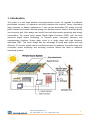
Grid Tie Solar Inverter
Operator's Manual
SG-4000
http://www.sysgration.com
Tel:886-2-8221-7111 Fax:886-2-8221-7112
1
IMPORTANT SAFETY INSTRUCTIONS
SAVE THESE INSTRUCTIONS
To reduce the risk of electrical shock and to ensure safe installation and
operation of Grid Tie Solar Inverter, please carefully read and strictly
follow all safety instructions and cautionary markings.
CAUTION — Risk of Electric Shock – Plates are live. Disconnect before servicing.
CAUTION — Risk of Electric Shock , Do NOT Remove Cover. No User Serviceable
Parts Inside. Refer Servicing To Qualified Service Personnel.
WARNING — For Continued Protection Against Risk Of Fire, Replace Only With
Same Type And Ratings Of Fuse.
CAUTION — To reduce the risk of electric shock and fire – Do not connect a circuit
operating at more than 150 volts to ground.
CAUTION — To reduce the risk of electrical shock, disconnect both AC and DC
power from the SG series Inverter before attempting any maintenance
or cleaning or working on any circuits connected to the inverter.
Turning off controls will not reduce this risk. Internal capacitors remain
charged for 5 minutes after disconnecting all sources of power.
WARNING — All electrical installation shall be done in accordance with local and
national codes ANSI/NFPA 70.
WARNING — Connecting this unit to the electrical grid shall only be performed by
qualified personnel and only after formal approval from the utility
company.
WARNING — This device contains no user serviceable parts inside. Please return the
unit to authorized Service Center for maintenance.
CAUTION — This unit should be mounted on firm background and under a shading
roof to avoid exposure to direct sunlight and rain.
CAUTION — Rear heat sink of this unit may exceed 80 °C (175° F ). Don’t touch to
avoid risk of burning.
http://www.sysgration.com
Tel:886-2-8221-7111 Fax:886-2-8221-7112
2
FCC Information to the User
This equipment has been tested and found to comply with the limits for a Class B digital
device, pursuant to part 15 of the FCC Rules. These limits are designed to provide
reasonable protection against harmful interference in a residential installation. This
equipment generates, uses and can radiate radio frequency energy and, if not installed and
used in accordance with the instructions, may cause harmful interference to radio
communications. However, there is no guarantee that interference will not occur in a
particular installation. If this equipment does cause harmful interference to radio or television
reception, which can be determined by turning the equipment off and on, the user is
encouraged to try to correct the interference by one or more of the following measures:
• Reorient or relocate the receiving antenna.
• Increase the separation between the equipment and the receiver.
• Connect the equipment into an outlet on a circuit different from that to which the receiver is
connected.
• Consult the dealer or an experienced radio/TV technician for help.
http://www.sysgration.com
Tel:886-2-8221-7111 Fax:886-2-8221-7112
3
Table of contents
1. Introduction
2. Installation
3. Wiring process
4. Operating procedure
5. System Structure
6. Electrical Specifications
7. Trouble shooting
http://www.sysgration.com
Tel:886-2-8221-7111 Fax:886-2-8221-7112
4
1. Introduction
The system is a two stage parallel circuit photovoltaic inverter. As opposed to traditional
photovoltaic inverters, no expensive and bulky batteries are required. Hence, eliminating
large expenses on battery maintenance. It can convert photovoltaic DC energy via solar
panel modules and inverts collected energy into alternate current, which is then fed directly
into the power grid. Such design can benefit from both direct power generating and energy
conservation. The control panel adopts Digital Signal Processor (DSP), with the most
advanced digital control technology, to increase power conversion efficiency and
supplementary functions. Output stage circuit is of single stage with high frequency
switchable IGBT. The circuit design has the advantage of being both simple and high
efficiency. PV inverter system can be monitored remotely via software. It provides users with
convenient power monitoring and recording functions without the need of additional
monitoring systems.
http://www.sysgration.com
Tel:886-2-8221-7111 Fax:886-2-8221-7112
5
2. Installation
Installation
Warning : All electrical installation shall be done in accordance
with local and national codes ANSI/NFPA 70.
Warning : Connecting the SG-4000 to the electrical grid shall only
be performed by qualified personnel and only after formal approval
from the utility company.
SG-4000 can be installed indoor where sufficient air circulation is available with ambient
temperature less then 50℃.
Outdoor installation should be under controlled environment where no direct sunlight would
reach, as excessive heating would damage internal components and should minimize
exposure to rain despite her high protection class NEMA 3R.
The unit should be installed in a location normally inaccessible to persons.
Avoid mounting on wall of resonant materials like wooden or plastic panels as SG-4000
may slightly vibrate when working under load.
Please install this unit at eye-height (over 1 meter), so that all information and status from
LCD display can be read easily. Also please provide sufficient space on both sides of the unit
so that Cautions and Ratings would be easily visible.
Mount only on firm background and with correct position as below :
mount straight or tilted to the back
never mount tilted to front
http://www.sysgration.com
Tel:886-2-8221-7111 Fax:886-2-8221-7112
6
Mounting of SG-4000
Place the metal fixing plate on the designated surface of the wall and mark the holes of the
screw.
Drill the holes and hammer in the wall anchors.
Place the metal fixing plate again and fasten the eight screws into their respective holes
109.05
180.00
60.00
60.00
60.00
180.00
Metal fixing plate
Mount the unit on the fixing plate. Be sure that the four hooks get into their respective
fixtures and settle down.
http://www.sysgration.com
Tel:886-2-8221-7111 Fax:886-2-8221-7112
7
Placement of SG-4000
Step1 : The screws will bracket fixed to the wall.
http://www.sysgration.com
Tel:886-2-8221-7111 Fax:886-2-8221-7112
8
Step2 : The PV-Inverter are installed on the bracket.
http://www.sysgration.com
Tel:886-2-8221-7111 Fax:886-2-8221-7112
9
Step3 : The PV-Inverter bottom side used screws fixed on the wall.
http://www.sysgration.com
Tel:886-2-8221-7111 Fax:886-2-8221-7112
10
3. Wiring process
The photovoltaic inverter wiring is as shown above.
WARNING —National Electrical Code (NEC) requires that the inverter be
connected to a dedicated circuit and no other outlets or device
may be connected to this circuit. See NEC Section 690-64(b)
WARNING —Follow local electrical codes and the National Electrical Code
(NEC), ANSI/NFPA 70. Use copper conductors only with minimum
12AWG , 105℃
℃ , 600V wire for power grid and minimum 10AWG , 105℃
℃,
600V wire for solar panel connections with the PV-Inverter.
Power cable selection:
AC wire: Black copper wires of 12 AWG or above should be used for alternate current
output.
Ground wire: For enclosure grounding, green or yellowish green copper wires of
12AWG or above should be used.
DC wire: For input to the unit from solar panels, the cross section area is dependent on
the length of the wire. Identifiable colored copper wires of 10 AWG or above, for both
positive and negative power supplies should be used.
http://www.sysgration.com
Tel:886-2-8221-7111 Fax:886-2-8221-7112
11
Wiring diagram please see below ~
http://www.sysgration.com
Tel:886-2-8221-7111 Fax:886-2-8221-7112
12
4. Operation
Start operation
Verify all breakers are at OFF position.
Use an electricians’ multi-meter to test and make sure that the input voltage at DC
disconnect is within the correct range (150-550VDC).
Check both the voltage and frequency of main power grid is within the normal range.
Connect the PV-Inverter to the utility by switching on AC Main breaker and AC disconnect
breaker.
Connect the PV-Inverter to PV strings by switching on DC disconnect breaker.
After switching on the system, the PV-Inverter will start boot up sequence. It will take a five
minutes to complete the self-test cycle, as well as confirmation of power grid voltage and
frequency.
After confirming the AC voltage is within the correct working range, sunbeams can start
generating electrical power for user’s household electrical appliance and excess power
will be fed to utility grid automatically.
PV-Inverter start completed after a period of time will be automatically converted to sleep
mode(LCD display turn off). Knock one time at the front panel can wake up unit.
Power On Screen
2000 01/01 00:00
SG-4000 VER 1.00
SG-4000
240V
Vs=240V F=60.0Hz
SG-4000
240V
PV=300V DCV=370V
Power on screen 1, show the date and model name.
Power on screen 2, show the model name and grid status.
Power on screen 3, show the model name and input status.
Count down Screen
Auto - start
after 300 sec
Count down 300 sec and start operating.
http://www.sysgration.com
Tel:886-2-8221-7111 Fax:886-2-8221-7112
13
Information Screen
Pin = 2000 W
Pout = 1950 W
Total
Today
2.30 kWH
1980 WH
Show input power and output power.
Show total generated power and today’s generated.
Auto - start
after 300 sec
Count down 300 sec and start operating.
2000 01/01 00:00
H TEMP. = 50.0 C
Show the date and the temperature.
2000 01/01 00:00
SG-4000 VER 1.00
PV=300V PI= 3.0 A
Vo =240V Io= 3.3 A
Power on screen 1, show the date and model name.
Show the input voltage and current, output voltage and current.
Knock the front panel can change the information display.
http://www.sysgration.com
Tel:886-2-8221-7111 Fax:886-2-8221-7112
14
5. System structure
System structure block diagram
System structure can be divided into the following sections:
1. DC/DC Converter:
A DC/DC converter is a circuit that accepts a solar panel input voltage and produces a
DC output voltage to inverter.
2. H-bridge Inverter:
By using SPWM circuit control technology, the inverter can invert electricity from DC into
AC and feeds current into AC grid directly.
3. Inverter control interface:
The inverter control interface provides control signals including A/D control, I/O
control, PWM drive and protection signals. With the support of control interface,
users can control and monitor and maintain the entire system.
4. DSP control:
DSP control can rapidly the computing and handle input and output of control signals.
5. MPPT control interface:
MPPT control interface could let solar panels in different illumination are able to issue the
largest power output.
http://www.sysgration.com
Tel:886-2-8221-7111 Fax:886-2-8221-7112
15
6. Electrical specifications
Capacity
Input
Output Power
4000W
Maximum Power
4000W
Norminal DC Voltage
300Vdc
Maximum PV open Voltage
550Vdc
MPPT Range
180 ~ 500Vdc
MPPT Range @ Full Load
240 ~ 440Vdc
Working Range
150 ~ 550Vdc
System Start-up Voltage
150Vdc
Maximum Input Current
20A
Operational Voltage
Operational Frequency
Output
Power Factor
208Vac ( 183~ 229Vac )
240Vac ( 212~ 264Vac )
50Hz ( 49.3 ~ 50.5 Hz )
60Hz ( 59.3 ~ 60.5 Hz )
> 0.99 @ full load
Current Distortion
< 5%
Maximum Efficiency
> 95%
Anti-Islanding
Yes
PV-Inverter meets the following requirements:
EMC: FCC Part15 Class B
Safety: IEEE929、IEEE1547.1、UL1741
Protection Degree : NEMA 3R
Acoustic Noise Level: < 40dB@1m
http://www.sysgration.com
Tel:886-2-8221-7111 Fax:886-2-8221-7112
16
7.Trouble shooting
Problem
Possible causes
How to correct
◎Check the wiring where abnormal?
◎Check the Mains frequency is within
Frequency error
Line frequency out of range
PLL Fault
No Line frequency signal
AC Over-Voltage
Line voltage too high
AC Under-Voltage
Line voltage too low
AC Over-Current
Output current too high
AC Over-Load
Output power over 4400W
PV Over-Voltage
PV input voltage over 550V
PV Under-Voltage
PV input voltage under 150V
PV Over-Current
PV input current too high
PV Over-Load
PV input power over 4800W
DV Over-Voltage
DC BUS voltage too high
◎Shutdown this unit and restart !
◎Increase the heat space around in the
Over-Heat
The device temperature too
high
the range of the specification?
◎Check the wiring where abnormal?
◎Check the Mains voltage is within the
range of the specification?
◎Check the output load is within the
spec, and not short-circuit?
◎Check the wiring where abnormal?
◎Check the PV input voltage is within
the range of the specification?
◎Check the output load is within the
spec, and not short-circuit?
case !
◎The machine installed in a cool place !
◎Shutdown this unit and restart !
DC-DC over curr
Converter short current
happened
DC-AC over curr
Inverter short current happened ◎Shutdown this unit and restart !
Line offset err
Line offset detected failure
◎Shutdown this unit and restart !
LOW PV voltage
PV input voltage too low
◎Low sun illumination !
Start error
Start operation failure
◎Shutdown this unit and restart !
Ground fault detected
◎Shutdown this unit and restart !
Ground Fault
◎Check the Ground wiring where
abnormal?
http://www.sysgration.com
Tel:886-2-8221-7111 Fax:886-2-8221-7112
17
http://www.sysgration.com
Tel:886-2-8221-7111 Fax:886-2-8221-7112
18