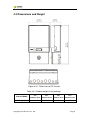
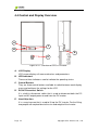
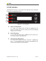
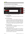
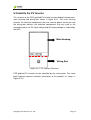
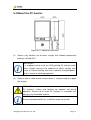
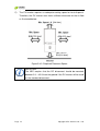
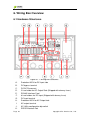
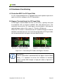
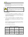
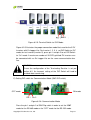
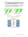
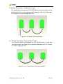
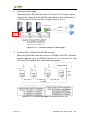
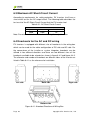
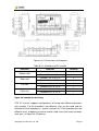
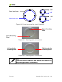
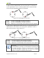
1
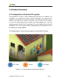
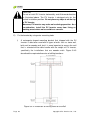
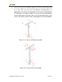
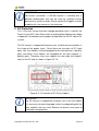
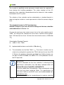
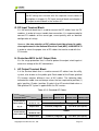
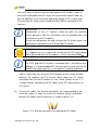
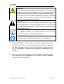
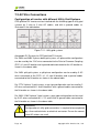
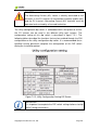
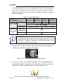
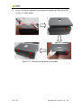
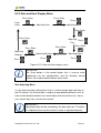
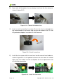
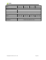
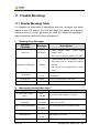
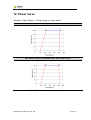
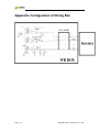
CPS SCE Series
Grid-tied PV Inverter
CPS SCE4KTL-O/US, CPS SCE5KTL-O/US
CPS SCE6KTL-O/US, CPS SCE7KTL-O/US
Installation and Operation Manual
CHINT POWER SYSTEMS AMERICA CO., LTD.
Contents
Before You Start… ------------------------------------------------------------------------------------------ 1
Important Safety Notification --------------------------------------------------------------------------- 2
1. Introduction ------------------------------------------------------------------------------------------------ 4
2. Limited Warranty ----------------------------------------------------------------------------------------- 5
3. Features Overview -------------------------------------------------------------------------------------- 6
4. Product Overview ---------------------------------------------------------------------------------------- 7
4.1 Introduction of Grid-tied PV system ---------------------------------------------------------- 7
4.2 Introduction of CPS Grid-tied PV Inverter -------------------------------------------------- 8
4.3 Dimensions and Weight ------------------------------------------------------------------------- 9
4.4 Control and Display Overview --------------------------------------------------------------- 10
4.5 LED Indicators ----------------------------------------------------------------------------------- 11
4.6 Control Buttons and LCD Displays --------------------------------------------------------- 12
5. Installation of PV Inverter --------------------------------------------------------------------------- 13
5.1 Open the package ------------------------------------------------------------------------------ 13
5.2 Visually check the PV Inverter --------------------------------------------------------------- 14
5.3 Identify the PV Inverter ------------------------------------------------------------------------ 15
5.4 Mount the PV Inverter ------------------------------------------------------------------------- 17
6. Wiring Box Overview --------------------------------------------------------------------------------- 26
6.1 Hardware Structures --------------------------------------------------------------------------- 26
6.2 Hardware Functioning ------------------------------------------------------------------------- 27
6.3 Maximum AC Short-Circuit Current -------------------------------------------------------- 40
6.4 Knockouts for the AC and DC wiring------------------------------------------------------- 40
7. Connecting the PV Inverter------------------------------------------------------------------------- 44
7.1 DC Wire Connections -------------------------------------------------------------------------- 44
7.2 AC Wire Connections -------------------------------------------------------------------------- 48
8. LCD Display and Function Structure------------------------------------------------------------ 55
8.1 First Level Display Menu ---------------------------------------------------------------------- 55
8.2 Second Level Display Menu ----------------------------------------------------------------- 56
8.2.1 Daily, Weekly and Monthly Energy Display Menu----------------------------- 56
8.2.2 Date and Hour Display Menu------------------------------------------------------- 57
9. Maintenance --------------------------------------------------------------------------------------------- 58
9.1 Replace the external cooling fan------------------------------------------------------------ 58
9.2 Clean the LCD Display ------------------------------------------------------------------------ 61
9.3 Install or Replace the DC/AC fuse ---------------------------------------------------------- 61
10. Specifications ----------------------------------------------------------------------------------------- 63
11. Trouble Shooting ------------------------------------------------------------------------------------- 66
11.1 Display Message Table ---------------------------------------------------------------------- 66
11.2 Trouble Shooting Actions -------------------------------------------------------------------- 68
12. Power Curve ------------------------------------------------------------------------------------------- 73
Appendix: Configuration of Wiring Box ----------------------------------------------------------- 74
Copyright CPS America Co., Ltd.
Before You Start…
This manual contains important information regarding installation and safe
operation of this unit. Be sure to read this manual carefully before using.
Thanks for choosing CPS Grid-tied PV Inverter (referred to in this manual as
“PV Inverter”, or simply “Inverter”). This PV Inverter is a highly reliable product
due to its innovative design and perfect quality control. Such an Inverter is
used in high demand, grid-tied PV systems.
If you encounter any problems during installation or operation of this unit, first
check this manual before contacting your local dealer or supplier. Instructions
inside this manual will help you solve most installation and operation
difficulties.
Please keep this manual on hand for quick reference.
Copyright CPS America Co., Ltd.
Page 1
Important Safety Notification
General
This user manual contains important instructions and notifications that must
be followed during installation and maintenance of the CPS grid-tied PV
Inverter.
The CPS grid-tied PV Inverter is a well-designed product through strict tests
to meet international safety requirements, but as an electrical and electronic
equipment, certain precautions must be observed during the installation and
operation of the PV Inverter.
In order to avoid personal injury during installation and daily operation of the
Inverter, users must read and follow all instructions, cautions and warnings
that are described in this manual.
Electrical Code
CPS grid-tied PV Inverters follow the National Electrical Code and other local
regulations to meet the requirements of electrical installation in the United
States. For the electrical installation in Canada, inverter installation must be
completed in accordance with applicable Canadian standards.
Safety Instructions
This manual contains important safety instructions to minimize the hazards to
people and equipments. Not following the procedures and practices correctly
could result in damage to or destruction of part or all of the CPS grid-tied PV
Inverter and/or other equipments connected to the Inverter or personal injury.
Preventive Regulation of Product
The Inverter should be installed, operated and maintained by qualified
personnel who have read and understood the operation instructions. The
qualification of the personnel is defined in the National Electrical Code.
Moreover, CPS grid-tied PV Inverters are provided with fixed trip limits and
shall not be aggregated above 30kW on a single point of common
connections.
Page 2
Copyright CPS America Co., Ltd.
Safety Symbols
ELECTRIC SHOCK
Electric shock indicates a potential risk of electric shock if not
avoided.
WARNING
Warning indicates a potentially hazardous situation that could
result in death or serious injury if not avoided.
CAUTION
Caution indicates a hazardous situation that could result in minor
injury if not avoided.
HOT SURFACE
Hot surface indicates a hot surface during operation that could
result in a burn injury if not avoided.
IMPORTANT
Important indicates important and useful information that the user
should know about the system.
ESD Protection
Risk of electric shock can occur when qualified service personnel
are dealing with the electrical components within the PV Inverter,
such as wiring box. An ESD glove should be worn during the
wiring operation, fuse replacement and component installation.
Tool Equipment Symbols
Multi-Meter
Multi-meter symbol indicates that a multi-meter is needed for
measuring to ensure the proper operational functionality of
components.
Tools
Tools symbol indicates that specific tools are required during
installation procedures.
Copyright CPS America Co., Ltd.
Page 3
1. Introduction
This manual describes all the information needed to install and operate the
following PV Inverter Models:
CPS SCE4KTL-O/US, CPS SCE5KTL-O/US, CPS SCE6KTL-O/US, and
CPS SCE7KTL-O/US
IMPORTANT
In order to avoid problems during the installation, it is
recommended to read the entire user manual before any
installation procedures.
Any improper usage may result in damage to the unit. Therefore, it is
important that all installation procedures shall be completed by qualified
personnel that have been trained to install and operate PV Inverters.
Moreover, this user manual only describes the information that is needed for
the CPS grid-tied PV Inverter and does not cover any installation information
relating to other equipments installed in the PV system. The following safety
instruction should be followed:
WARNING
It is necessary that only qualified personnel conduct the
installation and operation of the PV Inverter. Otherwise, risk of
damage to or destruction of part or all of the Inverter and/or other
equipments connected to the Inverter or personal injury due to
improper installation procedures or practices.
ELECTRIC SHOCK
Alternating Current (AC) and Direct Current (DC) sources are
directly connected to the terminals in the PV Inverter. In order to
prevent risk of electric shock before maintenance or installation, it
is necessary to ensure that all AC and DC terminals are
disconnected.
HOT SURFACE
Although the inverter is designed to meet international safety
standards, the surface of the inverter can become hot during
operation. Therefore, do not touch the heat sink or peripheral
surfaces during or shortly after operation.
Page 4
Copyright CPS America Co., Ltd.
ELECTRIC SHOCK
Risk of electric shock from energy stored in capacitors. Do not
remove the cover until three minutes after disconnecting all
sources of power supply and the service should be done by
qualified personnel.
2. Limited Warranty
The warranty policy of this product is specified in the contract; otherwise,
the warranty period is 10 years.
This warranty covers all defects due to design, components and
manufacturing. However, the warranty does not cover damages resulting from
the following circumstances:
Seal on the product is broken
Improper transportation and delivery
Improper installation and operation
Insufficient ventilation for the inverter
The Inverter has been misused, neglected, or abused
The Inverter has been used or stored in conditions beyond its
electrical or environmental specifications
The Inverter has been used for purposes other than for which it was
designed
The Inverter has been used beyond its stated specifications, operating
parameters and application
Acts of third parties, atmospheric discharges, excess voltage,
chemical influences, natural wear and tear and for loss and damage
in transit
Improper testing, operation, maintenance, adjustment, repair, or any
modification of any kind not authorized in writing by the inverter
supplier
The Inverter has been connected to other equipment with which it is
not compatible
Application beyond the scope of applicable safety standards or grid codes
(VDE, UL, etc.)
Acts of nature such as lightning, fire, storm, flood and vandalism, etc.
Repairs and/or replacement of parts or the device are made at the
manufacturer’s discretion. Defective parts or malfunction discovered during
installation should be presented in a written report for confirmation before
applying for replacement or repair. The damage report must be issued within
seven working days after receiving the PV Inverter. Manufacturer is not
responsible for damages beyond the scope of this warranty.
Copyright CPS America Co., Ltd.
Page 5
3. Features Overview
Max. energy yield CEC efficiency of 97%
Transformer-less Design
Field selectable voltage out: 208/240/277 Vac
Wide MPPT voltage operating range: 105-500V
Integrated NEC compliant wire raceway
Integrated PV system AC / DC disconnect switch
(4) branch circuit-rated Negative and Positive fused inputs
Performance Monitoring Package
LCD display with side pushbutton for nighttime monitoring
NEMA 3R enclosure
Meets UL1741 standard
Page 6
Copyright CPS America Co., Ltd.
4. Product Overview
4.1 Introduction of Grid-tied PV system
The grid-tied PV system is mainly composed of four parts: PV modules, DC
distribution unit, grid-tied PV inverter and AC distribution unit. When the PV
modules are exposed to sufficient irradiation, they will generate DC power.
First, the DC will be fed to the PV Inverter (via DC distribution unit). Then the
Inverter converts the DC to AC and feeds AC to the Public Grid via the AC
distribution unit. The AC power can be used directly by the local load, or it can
be sold to your energy supplier.
The following figure shows the general picture of a grid-tied PV System:
A
DC Power
B
Inverter
C
AC Power
Figure 4.1.1: General picture of grid-tied PV System
Copyright CPS America Co., Ltd.
Page 7
4.2 Introduction of CPS Grid-tied PV Inverter
CPS grid-tied PV Inverter converts direct current (DC) power generated by a
PV panel into alternating current (AC), which is compatible with the local
electric distribution network, also called the public grid.
The CPS grid-tied PV Inverter is designed with a transformer-less
topology. Therefore, CPS grid-tied PV Inverters will not be suitable with
PV modules that are required to have the negative (–) or positive (+)
polarity of PV modules connected to the ground. For such application,
please contact the supplier before proceeding.
Page 8
Copyright CPS America Co., Ltd.
4.3 Dimensions and Weight
Figure 4.3.1: Dimensions of PV Inverter
Table 4.3.1 Product weight in the package
Inverter Model
Net Weight (lbs)
CPS
CPS
CPS
CPS
SCE4KTL-O/US
SCE5KTL-O/US
SCE6KTL-O/US
SCE7KTL-O/US
86
90.4
101.4
101.4
Copyright CPS America Co., Ltd.
Page 9
4.4 Control and Display Overview
A
C
B
E
D
Figure 4.4.1: Overview of CPS PV Inverter
A.
LCD Display
LCD screen displays all measured values and parameters.
B.
LED Indicators
There are three indicators used to indicate the operating status.
C.
Control Buttons
They are three control buttons available to switch between each display
menu and configure the settings for the LCD.
D.
DC/AC Disconnect Switch
It is a built-in disconnect switch that is used to disconnect both the DC
input and AC output power to and from the PV inverter.
E.
Hand Grip Area
It is a carrying area that is used to lift up the PV Inverter. For the lifting,
two people are required due to the size and weight of the Inverter.
Page 10
Copyright CPS America Co., Ltd.
4.5 LED Indicators
CPS grid-tied PV Inverter has three built-in LED indicators which will provide
information of the operational status:
A
B
C
Figure 4.5.1: LED Indicators
A)
Power-On LED Indicator
It is a green LED indicator which will light up in green when the
feed-in DC voltage from PV array reaches the minimum operating
voltage for the PV Inverter.
B)
Fault LED Indicator
It is a red LED indicator that lights in red when the PV Inverter has a
fault during startup or operating period.
C)
Communication LED Indicator
It is a Green LED indicator that lights and flashes in green when
there is a communication device connected and working with PV
inverter via the RS232 or RS-485 interface.
Copyright CPS America Co., Ltd.
Page 11
4.6 Control Buttons and LCD Displays
CPS grid-tied PV Inverters are equipped with three control buttons which
could be used to switch between display menus.
A
D
B
C
Figure 4.6.1: Control buttons and LCD displays
A) Up Control Button
The up control button is used to advance the display menu or move
the cursor up
B) Enter Control Button
The enter control button is used to configure the settings such as
parameters or is used to activate the lock function of display menu.
To pause the display menu, the user can hold the enter control
button for more than two seconds until LCD displays a “Lock” text.
To release, the user can presses the same control button for another
two seconds again in order to release menu from the “lock” mode.
C) Down Control Button
The down control button is used to advance the display menu in the
opposite direction to the up control button.
D) Liquid Crystal Display (LCD)
A green color LCD screen is used to display the text messages of
the operating status, monitoring parameters, PV inverter failures
and inverter faults. Moreover, the LCD screen will be automatically
turn off after ten seconds if LCD is not manually operated using the
above control buttons or nighttime button.
Page 12
Copyright CPS America Co., Ltd.
5. Installation of PV Inverter
5.1 Open the package
The product package contains the following items (Table 5.1.1):
Item
Q’ty
Note
1 Photovoltaic Inverter
(1) PV-Inverter
(2) Mounting Bracket
1
Upon which Inverter be hang and mounted onto a wall
(3) Accessory Box
1
Contains all necessary accessories (Table 5.1.2)
Note: Please keep the package box in case of need for sending the product for
repair service.
▲ Table 5.1.1 Items in the package
The (3) Accessory Box contains items listed below.
Items
Q’ty
Purpose
Figure
User’s Manual
1
Installation and Operation Manual
Mounting Anchor
6
For bracket installation.
Screw (M4 )
6
Security Screw.(M4)
2
For security locking to Inverter
Terminal Connector
See*
For AC / DC Wires
▲ Table 5.1.2 Items in the accessory box
Terminal Connectors of AC/DC wires are provided for Each Inverter Model:
*Table 5.1.3 Number of terminal connector
Inverter
model
Wire
CPS
CPS
CPS
CPS
SCE4KTL-O SCE5KTL-O SCE6KTL-O SCE7KTL-O
Unit
/US
/US
/US
/US
6AWG
0
0
0
3+1
PCS
8AWG
1+1
1+1
4+1
1+1
PCS
10AWG
12+3
12+3
9+2
9+2
PCS
diameter
The number of spare parts is listed behind “+” in the above table.
Copyright CPS America Co., Ltd.
Page 13
5.2 Visually check the PV Inverter
It is important to check the PV Inverter for any visible damage, including the
LCD screen. If there are visible damages can be found, please contact the
dealer or supplier immediately.
WARNING
Due to the weight of the inverter, it is recommended at least 2
people lift the PV Inverter from the packing and also for the
mounting the PV Inverter on the wall.
CAUTION
It is important to use the correct lifting point to lift the PV Inverter
from the packing, as any improper carrying and moving could
result in serious injury or damage the unit.
Warning
Any modification of the PV Inverter is not permitted. Risk of
damage can be caused by any improper modification.
Page 14
Copyright CPS America Co., Ltd.
5.3 Identify the PV Inverter
The structure of the CPS grid-tied PV Inverter can be divided into two parts,
main housing and wiring box shown in figure 5.3.1. The main housing
contains the electrical components that are used for power conversion and
the wiring box contains the electrical components that are used as the
connection points for DC input voltage and AC output voltage as required by
the NEC.
Main Housing
Wiring Box
Figure 5.3.1: PV Inverters Structure
CPS grid-tied PV Inverter can be identified by the name plate. The name
plate indicates general electrical information of the product as shown in
Figure 5.3.2:
Copyright CPS America Co., Ltd.
Page 15
Figure 5.3.2: Main Housing Name Plate
A warning label plate is located in the left-hand side of PV Inverter as
indicated in figure 5.3.4. This warning label is used to indicate all important
notices that shall be known. When you are dealing with the general utility
system and DC generator, read and follow all notifications from the warning
label as a reminder in order to prevent any electric shock that can happen
during the configuration period.
Figure 5.3.4: Warning Label Plate
Page 16
Copyright CPS America Co., Ltd.
5.4 Mount the PV Inverter
Figure 5.4.1: Required Dimension
A)
Select a dry location, out of direct sunlight with ambient temperature
between -20 and 45°C.
IMPORTANT
It is important not to install the CPS grid-tied PV Inverter under
direct sunlight, because the exposure of direct sunlight may
cause an internal heating and also a reduction of output power,
which is known as derating protection.
B)
Select a wall or solid vertical surface which is strong enough to support
the inverter.
WARNING
PV Inverter’s surface and housing can become hot during
operation. Ensure not to install PV Inverters in a location that
contains any flammable material.
CAUTION
Ensure selected location has a sufficient space for air flow.
Copyright CPS America Co., Ltd.
Page 17
C)
The PV Inverter requires an adequate cooling space for heat dispersal.
Therefore, the PV Inverter must have sufficient clearance for the air flow
as illustrated below:
Figure 5.4.2: Required Clearance Space
IMPORTANT
The NEC requires that the DC disconnect should be mounted
between 3 ft ~ 6.5 ft from the ground if the PV Inverter will be used
as the standard disconnect.
Page 18
Copyright CPS America Co., Ltd.
D) Install Orientation
Selecting a proper orientation for the PV Inverter is very important. The PV
Inverter should be installed in a vertical position. In order to avoid heat
dissipating issues, ensure there are no any obstacles located or installed near
by the PV Inverter.
Figure 5.4.3: Installing Position and Location
Copyright CPS America Co., Ltd.
Page 19
CAUTION
Do not to install PV Inverter horizontally and tilt-forward direction
as illustrated above. The PV Inverter is designed only for the
vertical installation position. Do not place any objects on the top
of PV Inverter.
Moreover, PV Inverter may make noise during operation. As a
consideration, install the PV Inverter away from living or
working areas where noise could be a concern.
E)
Fix the bracket by using outer mounting holes
i)
A rectangular-shaped mounting bracket that shipped with the PV
Inverter is able to be used with all types of walls such as stone wall,
brick wall or wooden wall, but it is more important to ensure the wall
that is selected will be able handle with the weight of PV Inverter,
specifically the installations that are wooden walls. Figure 5.4.3
described the required dimension of drilling locations:
Figure 5.4.4: Dimension of Drilling Point for the Wall
Page 20
Copyright CPS America Co., Ltd.
ii)
There are 2 types of handling modes to install the mounting bracket
on a wall. The user can use the different screwing points as
appropriate. The corner screwing points or the central screwing point
as illustrated in the figures, below. To secure the mounting bracket,
mark 6 outer holes on the wall, drive in the 6 mounting anchors, then
screw in the 6 M4 screws to each screwing point as illustrated below:
Figure 5.4.5: Corner screwing fixing mode
Figure 5.4.6: Central Point Fixing Mode
Copyright CPS America Co., Ltd.
Page 21
WARNING
It is important to ensure the drilling location is not located on any
electric wiring within the wall.
F.
Mount the PV Inverter into the mounting bracket as illustrated below.
i)
Hook up the PV Inverter by aligning the opening of rear-side
enclosure and place the PV Inverter into each targeted wedge
points of the mounting bracket as illustrated below:
Figure 5.4.7: Install PV Inverter into mounting bracket
IMPORTANT
Check the mounting bracket again before the PV Inverter is hung
on the bracket. It is recommended to have least 2 service
personnel for this procedure due to the weight of unit.
Page 22
Copyright CPS America Co., Ltd.
ii) Secure the edge point of mounting bracket
In order to avoid the wiring box swaying due to weather, the security
screws for the wiring box must be tightening. There will be two pieces of
the M4 size screws found within accessories box. The tightening location
of mounting bracket was indicated in figure 5.4.8. Follow the below
instructions in order to complete the tightening procedures:
Figure 5.4.8: The edge point of mounting bracket
WARNING
The wiring box shall not be opened under dusty or moist weather.
Working with the exposed electrical components under in moist
weather is very dangerous, which might cause an electric shock
easily. In dusty weather, electrical components of the wiring box
might be damaged if there is heavy dust floating within air during
serving period. Please be aware and avoid.
CAUTION
It is necessary to disconnect the DC generator and AC Utility if
the wiring box is already wired with any DC or AC connection. It
is necessary to wait 5 minutes in order to ensure all the electrical
components are discharged.
ESD Protection
An ESD glove should be worn during the cable wiring, replacing
the fuses and installing the components.
iii) Turn off DC/AC disconnect switch from the wiring box as illustrated
below:
Figure 5.4.9: Turn off DC/AC disconnect switch
Copyright CPS America Co., Ltd.
Page 23
iv) Unfasten 2 pieces M4 and 4 pieces M5 screws from the top cover of
wiring box as illustrated below:
Figure 5.4.10: Remove the screws of DC/AC Wiring Box
Screwdriver
A M5 hexagon head screwdriver is required for the procedure.
Page 24
Copyright CPS America Co., Ltd.
v)
Remove the top cover of disconnect box and then find the
highlighted location from the below figure and then insert 2 M4 size
screws:
Figure 5.4.11: Screwing Location for the Security Screws
Copyright CPS America Co., Ltd.
Page 25
6. Wiring Box Overview
6.1 Hardware Structures
Figure 6.1.1: Wiring Box Structures
A.
B.
Protection MOV for DC Input side
DC bypass terminal
C.
D.
E.
F.
G.
DC/AC Disconnect
2 fuse holder for AC Output Side (Shipped with dummy fuses)
RS-485 Interface Card
8 fuse holders for DC Input (Shipped with dummy fuses)
DC input terminal
H.
I.
J.
Protection MOV for AC Output side
AC output terminal
AC Utility configuration dip switch
K.
RS232 Interface Port
Page 26
Copyright CPS America Co., Ltd.
6.2 Hardware Functioning
A. Protection MOV for DC Input Side
It is the surge protection that is equipped and used to protect input circuit
against excessive voltage on the DC connections.
B. Bypass Terminal block for DC Input Side
It is the bypass terminal block for solar (+) and solar (–) polarity that used
to co-operate with an external combiner box and external fuses. The
maximum current of this DC input bypass terminal block is 38A and the
required torque values of the screws is 17.4 lbf-in (20 Kgf-cm).
When the PV Inverter is connected to the PV module through an external
combiner and external fuses are used, the configuration of DC input cable
can be connected with the bypass terminal block directly.
Positive (+) Polarity Position
Negative (–) Polarity Position
Figure 6.2.1: Connecting DC Cables with Bypass Terminal
IMPORTANT
If the DC input cable is connected with the bypass terminal block
directly, it is important to ensure the limitation of maximum
current is below 38A through a single pair cable as figure 6.2.1
mentioned.
Copyright CPS America Co., Ltd.
Page 27
C. DC/AC Disconnect
It is the disconnect switch that is used to turn-on and turn-off the power of
the PV Inverter. The switch disconnects both the DC and AC voltage to
and from the PV Inverter.
Electric shock
It is important to avoid touching the DC and AC cabling area
during the procedures even if the AC/DC switch of PV inverter
has been switched off. This is because live powers still remaining
with the cables, please beware.
D. AC Protection
I)
If an external AC breaker or fuse protector is installed, it is not
necessary to implement AC protection fuses within the wiring box. The
specification of external breakers or fuses shall meet the recommended
ratings listed in the following table.
II)
If there is no external AC breaker or fuse protector installed, it is
recommended to have AC protection fuses installed to the AC side. And
the AC fuse that can be selected from the recommended list as below
table indicates.
To ensure the rating of the fuses that are used for the each model is
correct, it is strongly recommended the installer purchase the AC fuses
that have already been tested by CPS.
The recommended list for the AC Fuses:
Table 6.2.1: AC Fuse Specification
Model
Manufacturer
Part Numbers
Fuses Rating
CPS
SCE4KTL-O/US
Littelfuse
KLC 25
25A / 600VAC
Littelfuse
KLC 30
30A / 600VAC
CPS
SCE6KTL-O/US
Littelfuse
L50S 40
40A / 500VAC
CPS
SCE7KTL-O/US
Littelfuse
L50S 50
50A / 500VAC
CPS
SCE5KTL-O/US
Page 28
Copyright CPS America Co., Ltd.
E. RS-485 Card
The 485 interface card is located in the right-hand side position of the
wiring box and integrated and shipped with the PV Inverter.
SW2: Communication
Mode DIP switch
SW1: Terminating
Resistor DIP switch
Terminating Block
1st PoE RJ-45 Port
2nd PoE RJ-45 Port
Link LED
Power LED
Figure 6.2.2: Integrated 485 Interface Card
A) Link LED Indicator:
When an Ethernet cable is inserted in any RJ-45
port; the Link LED will light up in yellow color
and blink at 2Hz during signal transferring.
B) Power LED indicator:
It indicates the connectivity of RS-485 card and
it will be lit-up in green when the inverter is
active.
C) Definition of RJ-45 PoE Ports
8
1
Figure 6.2.3: RJ-45 PoE ports
Copyright CPS America Co., Ltd.
Page 29
Table 6.2.2: Definition of RJ-45 PoE Ports
PIN
NAME
1
Tx+
2
Tx-
3
Rx+
4
GND
5
GND
6
Rx-
7
VCC
8
VCC
Voltage
± 400mVp-p~±15Vp-p
+ 400mVp-p~+15Vp-p
- 400mVp-p~-15Vp-p
11V~12V
WARNING
Power on socket Pin 7 & Pin 8 are DC powered. Do not connect
other devices to this port as it may damage your device.
D) Setting DIP switch for Terminating Resistor (SW1 DIP switch)
OFF mode
ON mode
Pin 1 Pin 2
Figure 6.2.4: Terminating Mode
Press the pin 1 and pin 2 to set the DIP Switch into “on” mode for card in
the terminal inverter (farthest from Data Logger or PC). For all the others,
set it to “off”. Here is example for the configuration of 5 PV inverters,
which pictured in next page.
Page 30
Copyright CPS America Co., Ltd.
Intranet
OFF
OFF
OFF
OFF
ON
Pin 2
Figure 6.2.5: Terminal Switch to “ON” Mode
Figure 6.2.5 illustrates the proper connection model that used for the 5 PV
Inverters with Ez Logger Lite. For Inverter 1, 2, 3, 4, set DIP Switch to “Off”
mode; for last inverter (inverter 5), press pin 1 and pin 2 to set DIP Switch
to “On” mode. A maximum number of 20 CPS grid-tied PV inverters can
be connected with an Ez Logger Lite on the same communication bus
line.
CAUTION
Ensure the configuration of the Terminating Resistor is set per
section 6.2. An incorrect setting of the DIP Switch will lead to
unstable data transferring.
E) Setting DIP switch for Communication Mode (SW2 DIP switch)
OFF mode
ON mode
Pin 1 Pin 2
Figure 6.2.6: Communication Mode
Press the pin 1 and pin 2 of SW2 Dip switch in order to set the “ON”
mode for the RS-485 mode or the ”OFF” mode for the RS-232 mode.
Copyright CPS America Co., Ltd.
Page 31
F) Multiple Connections: Usage of Ethernet cable
Ethernet cable can be used to connect either port to another RS-485
card. The cable must be a “Straight Through cable” as shown in figure
6.2.7. And it is important to ensure the pin position of Ethernet cable is
configured by the same way as shown in figure 6.2.8.
Connection Type A
Connection Type B
Figure 6.2.7: Connecting Mode of Ethernet cable
Figure 6.2.8: Pin Definition of Ethernet cable
Page 32
Copyright CPS America Co., Ltd.
G) Multiple Connections - Combination Usage
The combined connection of RJ-45 PoE port and terminal block can be
implemented, but it is not recommended. However, figure 6.2.9 describes
an example of a mixed configuration use.
Figure 6.2.9: Mixed Connecting Mode
H) Multiple Connections: Terminal Block Usage
The terminal block that designed for the RS-485 card is used with
twisted wire pairs to establish the connection between each PV Inverter
as shown in figure 6.2.10.
Figure 6.2.10: Twisted Wires Connecting Model
Copyright CPS America Co., Ltd.
Page 33
I)
Connect to Data Logger
When wiring the RS-485 card from PV Inverter to PV Inverter, please
connect the same pin of the RS-485 card (Receive Pin to Receive Pin
and Transmit Pin to Transmit Pin) as figure shown in 6.2.11:
Data Logger
Ethernet
Internet
RS-485
Up to 1200M
DIP SW
<ON>
Up to 1200M
Up to 1200M
Inverter to Inverter Correct Pin Configuration:
RS485 Pin T+(Transmit+) to T+(Transmit+)
Pin T-(Transmit-) to T-(Transmit-)
Pin R+(Receive+) to R+(Receive+)
Pin R-(Receive-) to R-(Receive-)
Figure 6.2.11: Connecting mode for data logger
J)
Connect to PC via RS-485 to RS-232 converter
When wiring RS-485 card from Inverter to RS-485 to RS-232 Converter,
connect opposite pins of RS-485 (Receive Pin to Transmit Pin, and
Transmit Pin to Receive Pin). See framed area below.
Figure 6.2.12: Connecting Mode for RS-485 with RS-232
Page 34
Copyright CPS America Co., Ltd.
IMPORTANT
For further instructions, a RS-485 manual is available with a
detailed configuration that can be used by qualified service
personnel or system installer. Please contact the supplier in order
to obtain this user manual as the reference.
F. DC Protection
This is the over current and over voltage protection that is used for the
Direct Current (DC) side. Please refer to configuration diagram that shown
in Appendix I to connect have a proper configuration for the DC side of PV
system.
The PV Inverter is shipped with dummy fuses (solid aluminum cylinders in
the shape of the proper fuses). Since there are four pairs of DC input
ports, four fuse holders shall be equipped for the four positive (+) polarity
ports and others fuse holders are equipped for the four negative (-)
polarity ports. Therefore, there are supports to have eight fuse folders,
total, to the DC-side as shown in figure 6.2.13.
Figure 6.2.13: Location of DC Fuses Holders
IMPORTANT
The PV Inverter is shipped with a dummy fuse in the fuse holder.
It is necessary to select the proper series fuse depending with the
solar modules that are used. Remove all dummy fuses prior to
installation and operation.
Copyright CPS America Co., Ltd.
Page 35
The installer or qualified service personnel should select the required DC
fuses during the installing procedure. The rating selection of the DC
protection fuses should be selected based on the amount of solar modules
connected in the PV system.
The criterion of fuse selection can be calculated by a standard formula in
order to help the installer or service personnel to select the correct rating of
fuse.
The standard formula for DC Fuse Selection:
Nominal Voltage of fuse must be 600VDC Rating and the fuse should be
selected between 1.56 x Isc < IN
Assume the maximum short circuit current (Isc) of the solar module used is
4.85A. The rating of the selected fuse must have a nominal current greater
than 1.25 times but less than 1.6 times the short circuit current as 1.56 x Isc
< IN
Calculated by Standard Formula:
A) 4.85A x 1.56 = 7.56A
B)
Implemented the above result within 1.56 x Isc < IN
C)
The calculation result will be 7.56A < IN. That means installer must to
select a fuse rating that is greater than 7.56 A, but must lesser than 9.70
A. Refer to the products information provided from Littelfuse factory, we
are able to select KLKD008, 8A, 600VDC DC as the protection fuse for
the DC input side.
IMPORTANT
The fuse calculation for the fuse selection is referring to the
requirements (information) that had been indicated within the
National Electrical Code(NEC), ANSI/NFPA 70.
To ensure trouble-free fuse protection, Eaton recommends using
fuses that have been tested by Eaton. The specifications for
fuses from Littelfuse and KLKD series can be downloaded from
www.littelfuse.com.
It is important to follow the standard formula in order to select the
Page 36
Copyright CPS America Co., Ltd.
proper rating of fuse for DC protection. And the size of the DC
and AC wiring must to meet with the required size of cables as
description at chapter H) DC input terminal block and chapter J)
AC output terminal block in the section 6.2.
G. DC Input Terminal Block
It is the terminal block that is used to connect the DC cables from the PV
modules. In order to have a trouble free connection, it is recommended to
connect PV modules of the same type, same quantity, with an identical
configuration of strings.
However, the size selection of DC cables should be referred to cable
size requirement in the National Electrical Code(NEC), ANSI/NFPA 70
in order to select the proper size of DC cables that can be used with the
PV inverter.
H. Protection MOV for AC Output Side
It is the surge protection that is used to protect the output circuit against
excessive voltage of the AC connections.
I. AC Output Terminal Block
It is the terminal block that is used to connect AC cables from the utility
system, also known as the public grid. Each model of the Eaton grid-tied
PV Inverter requires different sizes of AC cables. The following table
indicated the cable size and torque values that are required for position (1)
pole / position (2) pole / position (3) pole in the AC terminal block when a
208 grid-tied PV system is applied with the PV inverter:
Table 6.2.3: Standard AC Cables
Model
Terminal block
CPS
CPS
Admissible
labeled with (1),
conductor size
(2), (3)
Torque value
10 AWG
8 AWG
o
15.6 lbf-in (18 Kgf-cm)
Copyright CPS America Co., Ltd.
o
33.1 lbf-in (38.1 Kgf-cm)
10AWG
conductor size
Torque value
6 AWG
90 C / 194 F, Copper
Admissible
labeled with (G)
CPS
SCE4KTL-O/US SCE5KTL-O/US SCE6KTL-O/US SCE7KTL-O/US
Terminal block
Terminal block
CPS
15.6 lbf-in (18 Kgf-cm)
33.1 lbf-in (38.1 Kgf-cm)
Page 37
IMPORTANT
The selection for the AC cable size for the Position 1 / Position 2 /
Position 3 is referred to the table 310.16 in the National Electrical
Code (NEC).
J. Utility Configuration DIP Switch
It is a utility configuration dip switch that is embedded within DC/AC wiring
box. This dip switch allows the user to do different configurations of the
PV Inverter in order to let it connect to the different public grid-tied PV
systems using the same inverter. The dip switch is located at the
right-bottom side of wiring box, which just under RS-485 interface card
and nearby the RS232 interface port as below shown in figure 6.2.14:
Figure 6.2.14: Utility Configuration DIP Switch
Page 38
Copyright CPS America Co., Ltd.
K. RS232 Interface (for service purpose)
The
CPS
gird-tied
PV
Inverter
is
equipped
with
a
versatile
communications interface and can be used with a stand-alone monitoring
software called “Pro Control” to monitor the operating status of a single
PV inverter or multiple PV Inverters through RS-485 or RS232 interface.
To activate the RS232 interface, the RS-485 interface card should be
disabled manually by switching off the SW2 DIP switch as shown in figure
6.2.15. Therefore, it is important to know the status of SW2 DIP switch
when service personnel are dealing with the communication interfaces.
Disable Configuration
Enable Configuration
Figure 6.2.15: Enable mode for the RS232 interface
Firmware upgrades are also available and can be done via RS 232 interface.
All PV Inverters are integrated with a DB9 socket for the RS232 interface as a
built-in interface in the wiring box. The pin assignment of DB9 socket is
shown in the table below:
PIN
Signal Assignment
1
N.C.
2
TxD
3
RxD
4
N.C.
5
Common
6
N.C.
7
N.C.
8
N.C.
9
N.C.
Figure 6.2.16: RS232 Interface Pin Assignment
Copyright CPS America Co., Ltd.
Page 39
6.3 Maximum AC Short-Circuit Current
According to requirements for safety protection, PV Inverters shall have a
short circuit test on the AC output circuit. The following table describes the
test result of the AC Short-Circuit Current that the PV Inverter had.
Table 6.3.1: AC Short-Circuit Current
Maximum Short-Circuit Current and Duration Period
Ipeak
Irms
Duration
306A
178A
<1s
Note: Do not exceed the Irms value for choosing the output breaker.
6.4 Knockouts for the AC and DC wiring
PV Inverters is equipped with different size of knockouts in the wiring box
which can be used for the cable configuration of DC-side and AC-side. For
the convenience of the installer or system integrator, knockouts can be
utilized in four different directions and there are two different sizes of the
knockouts available to be selected as shown in figure 6.4.2 and figure 6.4.3.
The diameter and number of knockouts on different sides of the Inverter are
listed in Table 6.4.1 as the reference for installation.
Left side
Right side
Back side
Bottom side
Figure 6.4.1: Knockout Directions of Wiring Box
Page 40
Copyright CPS America Co., Ltd.
Figure 6.4.2: Dimensions of Knockouts
Table 6.4.1: Knockouts of PV Inverter
Direction
Bottom side
Back side
Let side
Right side
Diameter
Quantity
Combo 1-1/4 in. & 1 in.
4
Combo 3/4 in. & 1/2 in.
4
Combo 1-1/4 in. & 1 in.
4
Combo 3/4 in. & 1/2 in.
4
Combo 1-1/4 in. & 1 in.
3
Combo 3/4 in. & 1/2 in.
1
Combo 1-1/4 in. & 1 in.
3
Combo 3/4 in. & 1/2 in.
1
Open the knockouts for wiring
CPS PV Inverter supports configurations of wiring from different directions
with conduits. For the knockouts, two different sizes can be used and the
diameter of these knockouts is shown in figure 6.4.2. Each knockout has two
different levels of opening area that can be used, inner level area and outer
level area, as figure 6.4.3 indicates.
Copyright CPS America Co., Ltd.
Page 41
0.75″
Outer level area
0.5″
1.25″
Inner level area
1″
Figure 6.4.3: Levels area and the size of Knockouts
Upper Knocking
Point
Lower Knocking
Point
Figure 6.4.4: Knocking points of inner level
Left-hand side
Right-hand side
Knocking Point
Knocking Point
Figure 6.4.5: Knocking points of outer level
Tools
A M4 size slotted screwdriver and hammer are required for
the opening procedure of knockouts.
Page 42
Copyright CPS America Co., Ltd.
In order to utilize an opening hole in the inner level area, it is necessary to
use the required tools such as a slotted screwdriver with a hammer to knock
at the certain point repeatedly as figure 6.4.6 indicated:
Figure 6.4.6: Knocking point of inner level
1st Step:
2nd Step:
Last Step:
Use tools to target upper strike point and knock it.
Use tools to target bottom strike point and knock it.
Repeat the 1st and 2nd steps until the hole of inner level is opened.
In order to dash an opening hole at outer level area, it is necessary to use the
required tools to strike (knock) at the certain points repeatedly in order to
open a hole for wiring as shown in figure 6.4.7.
Figure 6.4.7: Knocking point of outer level
1st Step:
Use tools to target left side strike point and knock it.
2nd Step:
Last Step:
Use tools to target right side strike point and knock it.
Repeat the 1st and 2nd steps until the hole of outer level is opened.
IMPORTANT
Be sure to follow all instructions to strike/knock-out the opening hole
by the proper procedures. Otherwise, the opening area of knockout
can be easily damaged if improper tools are used or any improper
procedures are done for the opening, please beware.
Copyright CPS America Co., Ltd.
Page 43
7. Connecting the PV Inverter
7.1 DC Wire Connections
Since the wiring box has been opened during mounting procedures, use
the necessary tools to knock out an opening hole in the desired location
on the wiring box for AC cables and insert a conduit as shown in figure
7.1.1. Second, remove the top cover of wiring box before this procedure
started. Please refer to the configuration diagram in Appendix I and
ensure a correct connection for the DC side of PV system.
Figure 7.1.1: Insert a conduit to the wiring box
IMPORTANT
Conduit is not a part of accessories supplied with the CPS
grid-tied PV Inverter. To ensure the protection class of the
inverter, it is important to use the water-proof conduits.
A)
Before plugging the DC connectors with the cables of PV strings, it’s
important to conduct polarity check by following the steps below:
i. Using multi-meter to measure the PV strings’ cable ends and check
the polarity
ii. The positive (+) terminal of cable should match the Female
Connector
iii. The negative (-) terminal of cable should match the Male Connector
Figure 7.1.2: Polarity checking
Page 44
Copyright CPS America Co., Ltd.
Use multi-meter to confirm the total input power of PV strings in order to
ensure the input power from PV strings will not exceed the permissible set
point of 600VDC as the maximum operating voltage of PV inverter and
the maximum DC input current should be within 20A for each pole of DC
terminal.
IMPORTANT
Configuration of the PV modules should be done by qualified
service personnel with the instructions that are provided from the
manufacturer of the PV modules.
Ensure the configuration for each string of the PV-system meets the
specifications required by the CPS grid-tied PV Inverter.
Multi-Meter
It is important to use a multi-meter to measure the DC input voltage
that is generated from the PV modules. It must not exceed 600VDC.
IMPORTANT
The CPS grid-tied PV Inverter is designed with a transformer-less
topology. It is recommended NOT connecting the Inverter with the PV
modules that require positive (+) or negative (-) polarity to ground.
And it is also necessary to have a circuit breaker or fuse switch installed
between PV modules and PV Inverter. When there are PV strings
connected with the circuit breaker or fuse switch, please ensure it is
turned off before connecting the DC cables to the DC input terminals of
PV inverter.
B)
For the DC cables, the terminal connectors are recommended to be
used with cables in order to ensure the effective electric conduction
between DC cables and DC terminals as shown in figure 7.1.2.
Figure 7.1.3: Terminal connectors are required for DC Cables
Copyright CPS America Co., Ltd.
Page 45
C)
Connecting DC cables of PV strings to the DC terminal by taking the
following steps:
DC -
DC +
Figure 7.1.4: DC terminal for PV inverter
i.
Select the proper rating for the string fuse by following the
calculation that had been mentioned in section G. DC Protection of
chapter 6.2
ii. Install the DC fuse in its assigned location
iii. Connecting DC positive polarity cable to the DC positive pole
terminal in the wiring box
iv. Tighten the DC positive polarity cable in the DC terminal by a
screwdriver with the required torque value
v. Connecting DC negative polarity cable to the DC negative pole
terminal in the wiring box
vi. Tighten the DC negative polarity cable in the DC terminal by a
screwdriver with the required torque value
vii. Double confirm the DC cable from the DC terminal in order to
ensure all the DC cables have been tighten firmly in proper location
as described in figure 7.1.5:
Figure 7.1.5: DC Input Terminal
IMPORTANT
The size selection of DC cables should be referred to the cable size
requirement in the National Electrical Code(NEC), ANSI/NFPA 70 that
can be used with the PV inverter, please beware of this.
Page 46
Copyright CPS America Co., Ltd.
WARNING
Do not mix the connection with the wrong polarity. This may cause
damage to the PV Inverter; therefore, it is very important to do the
polarity check before connecting the DC power to the wiring box.
Do not start up the PV Inverter while the fuse cover is removed.
The dummy fuses must be kept within fuse holder if there is no
protection fuses planned to be installed.
CAUTION
Each port (terminal) of the multi-string DC input terminal is only able
to be connected with a maximum 20A input current. It is important to
ensure the correct connections of the PV modules according to the
electrical specifications.
IMPORTANT
It is important to follow the standard formula for the DC fuse
selection if string fuses are planned to be used.
Insulation Protection
An insulation glove should be worn during the service period.
D)
When the DC power is delivered from an external combiner to the wiring
box of the PV Inverter, use a multi-meter to measure the DC voltage on
the connected polarity port of the DC input terminal in order to ensure
the DC input power is applied within the electrical specification of PV
inverter.
E)
At last, turn off the circuit breaker for the PV strings of DC input side and
then continue with the procedures in next section in order to complete
the connection for the AC side.
Copyright CPS America Co., Ltd.
Page 47
7.2 AC Wire Connections
Configuration of inverter with different Utility Grid Systems
CPS grid-tied PV Inverter can be installed with the following type of utility grid
systems by 2 wire or 3 wire AC cables, and with a ground cables as
illustrated in the table below.
Figure 7.2.1: Utility grid systems
Acceptable PV Systems for CPS grid-tied PV Inverter:
For 208V and 240V 3-phase delta grid system, a 3-phase delta configuration
can be used by the 2 AC wires connected to the Point of Common Coupling
(PCC) L1 and L2 location and a ground cable connected to the L2 location as
shown in the above table.
For 240V split grid system, a split-phase configuration can be used by 3 AC
wires connected to the PCC's L1, L2 and N location and a ground cables
connected to the N location as shown in the above table.
For 277V 3-phase Y grid system, a wye type configuration can be used by 2
AC wires connected to L1 and N locations with a ground cables connected to
the N location as shown in the above table.
For 208Y /120V 3-phase Y grid system, a wye type configuration can be used
by 3 AC wires connected to L1, L2, and N with a ground cable connected to
the N location as shown in the above table.
WARNING
Configuration of utility grid connections is required to be completed
by a licensed technician or electrical contractor. Ensure the correct
sized AC cables are used!
Page 48
Copyright CPS America Co., Ltd.
DANGER
The Alternating Current (AC) source is directly connected to the
terminals in the PV Inverter. All connections between public utility
and the PV inverter's Alternating Current (AC) terminals must be
operated and serviced by a licensed technician.
The utility-configuration dip switch is embedded within wiring box to ensure
the PV Inverter can be used in the different utility grid systems. The
configuration setting of this dip switch is described in figure 7.2.1. The
following tables described the functions that can be enabled through the PIN
configuration on the utility configuration dip switch. It is recommended that a
qualified service personnel complete the configuration of this DIP switch
during the installation period.
Figure 7.2.2: Utility Configuration Setting DIP Switch
IMPORTANT
It is important to complete the DIP switch settings before starting
the AC wiring connections.
Copyright CPS America Co., Ltd.
Page 49
Table 7.2.1: Utility Configuration
Utility Configuration
DIP switch Setting
Pin Pin Pin
1
2
3
AC Terminal
Description
LCD Display
1
DIP
2
switch
XKW 208
208 Delta:
ON OFF OFF
3
Corner
L1 L2
-
G
grounded
Corner
XKW 240
L1 L2
-
G
grounded
ON ON OFF
480 Y/277-V
Corner
grounded
240 Delta:
ON OFF ON
Delta:
Delta:
Corner
grounded
L1 L2
-
XKW
G
277Vac
System
240V:120V
split phase
ON ON ON
XKW
L1 L2
240V:120V
N
G
240Vac Split
Stinger
Page 50
Copyright CPS America Co., Ltd.
OFF OFF OFF
208Y/120-V
L1 L2
N
G
XKW
208Y/120-V
Note: The neutral conductor is required to be the same gauge as the phase
conductors.
Configuration for the AC Wiring:
A)
After the DC wiring connection is finished, start to dash an open hole for
the AC cables, insert the conduit, and tighten with the conduit gland.
Figure 7.2.3: Insert a conduit through an open hole
B)
Ensure the AC utility system is compatible with CPS grid-tied PV
Inverter. Confirm the specific kind of utility system being used, and then
select the corresponding setting of utility configuration DIP switch as per
the instructions in Table 7.2.1 before the procedures for AC connection.
C)
Use a multi-meter to measure the AC voltage from the combiner box for
AC utility. It is important to confirm the configuration of AC utility
matches with that of the utility configuration DIP switch.
D)
Refer to the information in the table 310.16 of the National Electrical
Code (NEC), and select the proper size of AC cables for the Position 1
pole / Position 2 pole / Position 3 pole. Refer to the column 2 of table
18.1 in the UL1741 electrical code, and select the proper size of ground
cable for the AC terminal.
Copyright CPS America Co., Ltd.
Page 51
The following table shows the information of cable size and torque
values that should be used in the position (1) pole / position (2) pole /
position (3) pole in the AC terminal when a 208V grid system is applied
with the PV inverter.
Table 7.2.2: AC Cables Size
Inverter Model
Terminal block
CPS
CPS
CPS
CPS
SCE4KTL-O/US SCE5KTL-O/US SCE6KTL-O/US SCE7KTL-O/US
Terminal block
Admissible
labeled with
conductor size
(1), (2), (3)
Torque value
Terminal block
Admissible
labeled with
conductor size
(G)
Torque value
10 AWG
8 AWG
o
6 AWG
o
90 C / 194 F, Copper
15.6 lbf-in (18 Kgf-cm)
33.1 lbf-in (38.1 Kgf-cm)
10AWG
15.6 lbf-in (18 Kgf-cm)
33.1 lbf-in (38.1 Kgf-cm)
IMPORTANT
The selection for the AC cable size and required torque values for
the Position 1 / Position 2 / Position 3 is referred to the table 310.16
in the National Electrical Code (NEC).
E)
Connect the AC cables with PV inverter by inserting them through the
conduits into wiring box as figure 7.2.4 shown:
Figure 7.2.4: Insert the AC cables through conduit
F)
For the AC cables, the terminal connectors are recommended to be
used with AC cables in order to ensure the effective electric conduction
between AC cables and AC terminals as shown in figure 7.2.5.
Figure 7.2.5: Terminal connectors are required for AC Cables
Page 52
Copyright CPS America Co., Ltd.
G)
Confirm the selected grid system is compatible with the PV inverter.
Then connect the AC cables to correct positions as per the symbol on
the configuration label for the AC cables in the wiring box.
Figure 7.2.6 shows the AC cable connections when a 208V grid system
is applied with the PV inverter. L-phase cable is connected to position (1)
pole, Neutral cable is connected to position (2) pole and ground cable is
connected to the ground symbol pole. On the other hand, please ensure
the setting of the AC DIP switch has been set correctly with the applied
grid system.
Figure 7.2.6: Connect the AC Cables to Correct Positions
H)
Tighten the screws for the AC cables with the required torque values as
listed in the Table 7.2.2. Then turn on the circuit breaker from the utility
panel or switchboard, and use a multi-meter to measure whether the AC
voltage of PV system is normal and the connection is correct.
I)
Check the condition of the conduits again to ensure all conduits are
tightly locked and sealed for the protection against rain and dust before
the top cover is reinstalled on the wiring box.
Copyright CPS America Co., Ltd.
Page 53
J)
Lastly, reinstall the top cover of wiring box by tightening 2*M4 and 4*M5
screws as shown below:
Figure 7.2.7: Reinstall the top cover of wiring box
Page 54
Copyright CPS America Co., Ltd.
8. LCD Display and Function Structure
8.1 First Level Display Menu
Operation Status
Output Power
Definition of Level 1 display menu
Operating and Output power Status
Display the operation status and the
instant-output power of the unit.
Press
Etoday
Energy
Press
Date
Hour
Etoday and Energy Menu
Display the output energy that is produced on
the current day and the total energy that is
produced since the PV Inverter was installed.
Date and Hour Menu
Display date and time of the current day.
Press
DC Input Voltage
DC Input Current
DC Voltage and DC Current Menu
Display the DC voltage and DC current from the
PV array.
Press
AC Output Voltage
AC Output Current
AC Voltage and AC Current Menu
Display the output AC voltage and AC current.
Press
Frequency
Output Power
Frequency and Output Power
Display the AC frequency and the instant-output
power of the unit.
Press
Nominal Power
Grid System
Nominal Power and Grid System Menu
Display the nominal power of the PV Inverter
and voltage of the AC utility system.
Press
Model name
Version
Model Name and Version
Display Model name and the firmware version.
Figure 8.1.1: First level display menu
Copyright CPS America Co., Ltd.
Page 55
8.2 Second Level Display Menu
8.2.1 Daily, Weekly and Monthly Energy Display Menu
Press Enter
Press Enter
Press
Etoday
E-Day
Energy
Press
Date
Output Energy
Press Enter
Press
Week
Output Energy
E-Week
Press
Press Enter
Press
Month
Output Energy
Press
Press Enter
Press Enter
EXIT
Figure 8.2.1: Second level display menu
E-Day Display Menu
It is a menu that will display the output energy for the past 30 days.
E-Week Display Menu
It is a menu that will display the output energy for the past 52 weeks.
E-Month Display Menu
It is a menu that will display output energy for the past 12 months.
EXIT Display Menu
It is a menu that is used to return back to Etoday menu, the level 1 display
menu.
Page 56
Copyright CPS America Co., Ltd.
8.2.2 Date and Hour Display Menu
Press Enter
Press Enter
Press
Date
Hour
Adjusting Year
Adjusting Month
Press Enter
Press Enter
Adjusting Press
Day
Press Enter
Press Enter
Adjusting
Seconds
Adjusting Minutes
Press
Press
Press Enter
Adjusting Hours
Press
Figure 8.2.2: Date and Hour display menu
IMPORTANT
The Enter button is the control button that is used to enter
subdirectory for the configurations and the direction control
buttons are used to rotate between each menu.
Date Adjusting Menu
It is the date and hour setting menu that is used to change date and time of
the PV Inverter. The Enter button is used to change between different units of
time and the direction buttons are used to adjust the value of the unit, such as
year, month, day, hour, minute and second.
IMPORTANT
Operational data will be recorded by the date and hour. Therefore,
it is important to ensure the time of inverter is adjusted correctly.
Copyright CPS America Co., Ltd.
Page 57
9. Maintenance
9.1 Replace the external cooling fan
For CPS SCE4KTL-O/US and CPS SCE5KTL-O/US models, there is no
cooling fan designed for the external housing, but an internal fan designed in
PV inverter for the thermal management. Therefore, “FAN Lock” is the only
failures message that user will receive from the LCD if the operation of
internal cooling fan has failed. If this situation happens, please contact our
after-sales service center for further instructions.
For CPS SCE6KTL-O/US and CPS SCE7KTL-O/US models, there is an
external cooling fan and the internal cooling fan designed in PV inverter for
the thermal management.
The external fan is located at the top of PV Inverter as shown in figure 9.1.2.
When the cooling fan is not working properly, user will receive three different
kinds of failure messages from the LCD.
1. “FAN Lock” is the first kind of failure message that will be shown on the
LCD when both external and internal cooling fans are not working properly.
2. “FAN1 Lock” is the second kind of failure message when the external
cooling fan is not working properly.
3. “FAN2 Lock” is the third kind of failure message when the internal cooling
fan is not worked properly.
If “FAN1 Lock” is indicated on the CPS SCE6KTL-O/US and CPS
SCE7KTL-O/US models, please check whether there is any obstacle
(stopping) blocking the external fan. When no obstacle is found, users can
follow the procedures to change the external cooling fan to see whether the
cooling fan problem can be fixed by changing a new cooling fan. If the “FAN
Lock” or “FAN2 Lock” is indicated on the CPS SCE6KTL-O/US and CPS
SCE7KTL-O/US models, please contact our after-sales service center for
further instructions since the internal cooling fan is not working properly.
IMPORTANT
If the “FAN2 LOCK” is indicated on the CPS SCE6KTL-O/US and
CPS SCE7KTL-O/US models or “FAN LOCK” on the CPS
SCE4KTL-O/US and CPS SCE5KTL-O/US models, this means
the interior cooling fan inside the main housing of PV Inverter is
probably defective and needs to be replaced. Please contact our
after-sales service center for further assistance.
Page 58
Copyright CPS America Co., Ltd.
If the cooling fan is too dirty, a vacuum cleaner can be used to clean the PV
Inverter from the top. If the cleaning procedure does not fixed the problem,
call our after-sales service personnel to determine the status of the cooling
fan and make a replacement. The following procedures describes how to
change the cooling fan, please read and understand all procedures before
doing so.
A)
Switch off the DC/AC disconnect switch and wait for at least three
minutes to discharge the stored energy in the PV inverter.
Figure 9.1.1: Turn off DC/AC switch
B)
Unfastening all screws located in each corner as highlighted in figure
9.1.2. After the screws are removed, take off the top cover of the cooling
fan from PV Inverter as shown in the figure below:
Figure 9.1.2: Screws for the external cooling fan
Copyright CPS America Co., Ltd.
Page 59
C)
Taken out the cooling fan, and then disconnect the power cable of the
cooling fan as shown in Figure 9.1.3.
Figure 9.1.3: Disconnect the power cables of the cooling fan
D)
Replace with a new cooling fan by connecting its power cable to PV
Inverter. Then re-tighten the 4 screws at the top cover.
E)
Switch on the DC/AC disconnect switch to complete the fan
replacement procedure.
Page 60
Copyright CPS America Co., Ltd.
9.2 Clean the LCD Display
If the screen of the LCD display and the LED indicators are dusty and not
readable, please use a piece of damp cloth to clean the surface.
9.3 Install or Replace the DC/AC fuse
Insulation Protection
The insulation gloves should be worn during wiring, replacing
fuses and installing components.
ELECTRIC SHOCK
There is a risk of electric shock from the energy stored in the
capacitors. Therefore, it is necessary not to remove the top cover
of wiring box until 3 minutes after DC/AC disconnect switch is
turned off.
It is necessary to turn off the external DC/AC breakers if they
exist. Otherwise, it is important to disconnect all the PV modules
and AC utility connections before the service of fuse
replacement. The PV Inverter must be disconnected from all
sources of power supply. Refer service to only qualified service
personnel.
IMPORTANT
The selection of the DC fuses must follow the instructions
outlined in chapter f. DC protection of section 6.2 within the
manual.
A)
Remove the fuse cover from the fuse holders as shown in figure 9.3.1:
Figure 9.3.1: Remove the fuse cover
Copyright CPS America Co., Ltd.
Page 61
B)
Next, take off the broken fuse or dummy fuse from the fuse cover as
shown in figure 9.3.2:
Figure 9.3.2: Take off the broken fuse
C)
Insert a new fuse into the fuse cover. Ensure the fuse is selected from
the recommended list of brands and rating as described in the DC and
AC protection chapters in section 6.2 of this manual.
Figure 9.3.3: Install a new fuse
D)
Install the fuse cover with the new fuse into the correct fuse holder as
shown in figure 9.3.4. It is important to ensure the fuse cover is inserted
tightly into fuse holder in order to complete the fuse replacement and
re-installation procedure.
Figure 9.3.4: Install the fuse cover
Page 62
Copyright CPS America Co., Ltd.
10. Specifications
CPS
CPS
CPS
CPS
SCE4KTL-O/US
SCE5KTL-O/US
SCE6KTL-O/US
SCE7KTL-O/US
Model
Market
North America
Input (DC)
Max. PV Power
4.8 KW
6 KW
7.2 KW
8.4 KW
Nominal DC Input Power
4.1KW
5.2KW
6.2KW
7.3KW
Nominal DC voltage
360 V
360 V
360 V
360 V
Max. PV open voltage
600 V
600 V
600 V
600 V
Start-up DC Input Voltage
150 V
150 V
150 V
150 V
100 ~ 515 V
100 ~ 515 V
100 ~ 515 V
100 ~ 515 V
225 ~ 500 V
200 ~ 500 V
200 ~ 500 V
200 ~ 500 V
Number of MPP tracker(s)
1
1
1
1
Number of DC Input Pairs
4
4
4
4
Operating DC Input Voltage
1
Range
MPPT Voltage Range
Max. DC current
19 A
26 A
32 A
37 A
Max. Input Current per String
20A
20A
20A
20A
2
DC insulation resistance
> 2MΩ
DC Disconnection Type
Switch
Output (AC)
Nominal AC power @ 240Vac &
4000W
5000W
6000W
7000W
3800W
4600W
6000W
7000W
4000W
5000W
6000W
7000W
3800W
4600W
6000W
7000W
277Vac
Nominal AC power @ 208Vac
Max. AC power @ 240Vac &
277Vac
Max. AC power @ 208Vac
Grid Connection Type
Single phase / 240V Split phase (Refer to 5.4)
Rated Output Voltage
240V Split phase
Operational voltage
range
/ Firmware setting
value
208V
3
186~225V
system
240V
4
215~260V
system
1
This is the DC voltage range that inverter can feed power to the grid.
The DC resistance requirement for positive or negative terminal to chassis ground.
3
Regulation range: 183~229Vac
4
Regulation range: 211~264Vac
2
Copyright CPS America Co., Ltd.
Page 63
CPS
CPS
CPS
CPS
SCE4KTL-O/US
SCE5KTL-O/US
SCE6KTL-O/US
SCE7KTL-O/US
Model
277V
248~300V
5
system
Rated Output Frequency
60Hz
Power Factor
>0.99
Output Frequency Range
6
59.3-60.5Hz
Current THD
<3%
AC Disconnection Type
Switch
Nominal AC current @ 208Vac
18.3A
22.1A
28.9A
33.7A
Nominal AC current @ 240Vac
16.7 A
20.8 A
25 A
29.2A
Nominal AC current @ 277Vac
14.4 A
18.1 A
21.7 A
25.3A
18.5A
22.5A
30A
35A
18.5A
22.5A
28.5A
33.2A
16.4A
20.5A
24.6A
28.7A
7
Max. AC current @ 208Vac
system
7
Max. AC current @ 240Vac
system
7
Max. AC current @ 277Vac
system
System
Topology
Transformerless
Max. Efficiency
97.5%
CEC efficiency
97%
8
Stand-by / Night Consumption
<7W / <0.2W
Environment
Protection Degree
NEMA 3R
Cooling
Forced air cooling
Operating Humidity
0-95%, non-condensing
Operating Altitude
Operating temperature range
6562ft / 2000m without derating
9
-25 ~ +50
℃
5
Regulation range: 244~305Vac
Regulation range: 59.3~60.5 Hz
7
The max OCPD( Over Current Protection Device) rating should not exceed the value in Table 6.3.1
8
Test condition of night power consumption: 240Vac
6
9
℃
℃
The LCD panel working temperature must be above -20 . The inverter can work normally without LCD display between -20
℃
and -25 .
Page 64
Copyright CPS America Co., Ltd.
CPS
CPS
CPS
CPS
SCE4KTL-O/US
SCE5KTL-O/US
SCE6KTL-O/US
SCE7KTL-O/US
Model
Display and Communication
LCD + LED
Display
RS232, RS485
Communication
Mechanical Data
Dimensions (WxHxD)
Weight
17.0x33.4x8.4in / 434x850x213mm
86lbs / 39kg
90lbs / 41kg
101lbs / 46kg
101lbs / 46kg
Safety
Safety and EMC Standard
Grid Standard
Copyright CPS America Co., Ltd.
UL1741: 2010, CSA C22.2 No.107.1-01, FCC PART15 Class B
IEEE1547: 2003, IEEE1547.1: 2005
Page 65
11. Trouble Shooting
11.1 Display Message Table
It is important to understand all operational and error messages that could
appear on the LCD display. The error messages that appear are especially
important because service personnel will need this information reported in
order to help them define the failure and correct it.
I)
Working Status Messages
Operation
Condition
Messages
Descriptions
1. Initial condition: Before system startup
Power Off
No Display
voltage (150V)
2. PV Inverter is totally shutdown, Vpv < 80V
1. Initial condition: When PV voltage is higher
than 150V, inverter is waiting for feeding to
Initialization and Waiting
Waiting
the grid
2. After Startup: Input voltage range is at 80 ~
100V
Check Grid
II)
Checking
xxxS
When PV voltage > 150V, inverter is checking
grid conditions
Feeding Grid
Normal
Inverter is feeding power to the grid
FLASH
FLASH
FLASH Firmware
Monitoring Parameter Messages
Operation Condition
Messages
Instantaneous Output
Pac=
Power
xxxx.xW
Cumulated energy
Energy=
information
xxxxxxkWh
Today’s energy information
Grid Voltage
Grid Frequency
Feeding Current
Page 66
Etoday=
xxx.xkWh
Vac=xxx.xV
Frequency =
xx.xHz
Iac=xx.xA
Descriptions
The real time output power in xxxx.xW
Total energy that has been fed to the grid since
inverter was installed
Daily energy that has been fed to the grid
Grid voltage in xxx.x VAC
Grid frequency in xx.xHz
Feeding current amount in xx.xA
Copyright CPS America Co., Ltd.
III)
PV Array Voltage
Vdc=xxx.xV
PV Array Current
Idc=xx.xA
Input voltage from PV array, xxx.xVDC
Input current from PV array, xx.xA
System Information Messages
Operation Condition
Model Display
Messages
CPS
SCExKTL-O/US
LCD Display Lock
Lock
Waiting for reconnecting
Reconnect in
to the grid
xxx S
Descriptions
Inverter Model
Hold the present display message
The time for reconnecting to the grid
IV) System Fault Messages
Operation Condition
Isolation Failure
Isolation
Fault
Grid Failure
Grid Fault
No Utility
No Utility
Input Voltage
PV over
too High
voltage
Ground I Fault
V)
Messages
Ground I
Fault
Descriptions
Ground-fault of the PV-modules or failure of
surge voltage protection
Measured data from Grid is beyond the
specification (voltage & frequency)
Utility is not available
Input voltage higher than the 600V
Leakage current on ground conductor is too high
Inverter Fault Messages
Operation Condition
Consistent Fault
Messages
Consistent
Fault
Fan Lock
Fan Lock
Fan1 Lock
Fan1 Lock
Fan2 Lock
Fan2 Lock
Temperature too high
Output Relay Failure
Over
temperature
Relay failure
Copyright CPS America Co., Ltd.
Descriptions
The readings of 2 microprocessors are not
consistent. It could be caused by CPU and/or
other circuit not functioning properly.
All the cooling fans of the unit are locked and not
functioning (All models)
Internal
fan
abnormal
(only
for
CPS
SCE6KTL-O/US and CPS SCE7KTL-O/US)
External
fan
abnormal
(only
for
CPS
SCE6KTL-O/US and CPS SCE7KTL-O/US)
The internal temperature is higher than normally
allowed value
The relay between the inverter and grid is not
functioning
Page 67
Output DC Injection too
high
EEPROM Problem
Operation Condition
Communication failure
between microprocessors
DC bus voltage is
DC Inj high
EEPROM
failure
Output DC current injection is too high
The inside EEPROM has data access problem
Messages
SCI failure
Descriptions
Communication between the inside MCU is
abnormal
High DC bus
The DC BUS inside is higher than expected
GFCI detection abnormal
GFCI Failure
The GFCI detection circuit is abnormal
Resistance stick abnormal
Damp Fail
too high
The function of resistance stick is abnormal
11.2 Trouble Shooting Actions
Trouble shooting action for System Faults Messages
A) Isolation Fault
Conditions: The resistance between the PV + or PV – and grounding is
outside the permissible range, <2MΩ.
Corrective Actions:
Restart the inverter again.
If fault still occurs after the unit is restarted, contact the system
installer immediately
Ask the system installer to check if the PV Inverter and PV Modules
are properly insulated throughout the solar system.
B) Grid Fault
Conditions: The grid voltage or grid frequency of the PV Inverter is not
within the permissible range. This can be caused by improper connection
of the AC side; wrong setting of the utility dip switch or the local grid
condition is out of acceptable range.
Corrective Actions:
Check the grid voltage and frequency information from the LCD
displays
Page 68
If the detected grid voltage is within permissible range, restart the
Copyright CPS America Co., Ltd.
PV Inverter and try again. If fault remains, contact the system
installer to check the grid voltage and cable connections between
PV Inverter and Utility system.
If detected grid voltage is out of permissible range, contact the
system installer to check the feed-in AC voltage and contact the
utility operator for further action.
C) No Utility
Conditions: Utility is not available. This can occur if the AC fuse is broken,
No AC connections from utility system, or broken AC cables.
Corrective Actions:
Check the Utility system and the AC connections of the PV Inverter
Check the AC fuses of the PV Inverter
If failure remains, disconnect the PV Inverter and contact the system
installer.
D) PV Over Voltage
Conditions: DC voltage fed by the PV module is higher than permissible
range, 600Vdc.
Corrective Actions:
Disconnected PV modules immediately.
Check the configuration of the strings for the PV modules and
ensure the maximum input voltage is lower than 600V.
E) Ground I Fault
Conditions: Leakage current on ground conductor is too high.
Corrective Actions:
Check the AC Cables Connections, especially the grounding cables.
Ensure all the cables are connected properly.
Restart the PV Inverter.
If fault remains, disconnect the PV Inverter and contact the system
installer.
Copyright CPS America Co., Ltd.
Page 69
Trouble Shooting Actions for Inverter Faults Messages
A) Consistent Fault
Conditions: The readings between two microprocessors of control board
are not consistent. It could be caused by the DSP and/or other circuits not
functioning properly.
Corrective Actions:
Restart the PV Inverter.
If fault remains, disconnect the PV Inverter and contact the inverter
installer.
B) FAN1 Lock (CPS SCE6KTL-O/US and CPS SCE7KTL-O/US)
Conditions: The external cooling fan of PV Inverter is not working
properly.
Corrective Actions
Visually check the front cooling fan and remove the obstacle if any.
If the top fan is not functioning, it may be replaced as per the
instructions described in section 9.1.
If fault remains, disconnect the PV Inverter and contact the inverter
installer.
C) Over Temperature:
Conditions: The internal temperature is higher than normal value
Corrective Actions:
Disconnect PV Inverter for a period of time (>30 minutes) and then
restart the PV Inverter.
If fault remains, disconnect the PV Inverter and contact the inverter
installer. Select a new location for the installation if it is necessary.
D) Relay Fault:
Fault Conditions: The relay between inverter and grid is not functioning.
Corrective Actions:
Restart the PV Inverter.
Page 70
If fault remains, disconnect the PV Inverter and contact the inverter
installer.
Copyright CPS America Co., Ltd.
E) DC Inj. high
Fault Conditions: Output DC current injection is too high.
Corrective Actions:
Check the connection of the DC Input.
Restart the PV Inverter.
If fault remains, disconnect the PV Inverter and contact the inverter
installer.
F) EEPROM Failures
Conditions: EEPROM inside has data access problem.
Corrective Actions:
Restart the PV Inverter.
If fault remains, disconnect the PV Inverter and contact the inverter
installer.
G) SCI failure
Conditions: Communication between the inside MCU is abnormal.
Corrective Actions:
Restart the PV Inverter.
If fault remains, disconnect the PV Inverter and contact the inverter
installer.
H) High DC bus
Conditions: The DC BUS inside is higher than expected.
Corrective Actions:
Restart the PV Inverter.
If fault remains, disconnect the PV Inverter and contact the inverter
installer.
Copyright CPS America Co., Ltd.
Page 71
I) GFCI Failure
Conditions: The GFCI detection circuit is abnormal.
Corrective Actions:
Check the grounding cable of the PV Inverter
Restart the PV Inverter.
If fault remains, contact the inverter installer to check the grounding
of the PV Inverter.
If the fault remains, disconnect the PV Inverter and contact the
inverter installer.
J) Damp Fail
Condition: The resistance stick is working outside the permissible range.
.
Corrective Actions:
Restart the PV Inverter.
If fault remains, disconnect the PV Inverter and contact the inverter
installer.
Page 72
Copyright CPS America Co., Ltd.
12. Power Curve
Allowable Output Power vs. String Voltage as shown below.
CPS SCE4KTL-O/US
CPS SCE5KTL-O/US, CPS SCE6KTL-O/US, CPS SCE7KTL-O/US
Figure 12.1.1: Line loss vs. cable length
Copyright CPS America Co., Ltd.
Page 73
Appendix: Configuration of Wiring Box
Page 74
Copyright CPS America Co., Ltd.
CHINT POWER SYSTEMS AMERICA CO., LTD.
Address: 700 International Parkway, Suite 102
Richardson, Texas 75081
Service Hotline: 855-584-7168
Email: [email protected]
SHANGHAI CHINT POWER SYSTEMS CO., LTD.
Headquarters: Building 4, No. 855, Wenhe Road,
Songjiang District, Shanghai, China
Tele: +86 -21 -3779 1222 -6300
Fax: +86 -21 -3779 1222 -6001
Website: www.chintpower.com/na/
This manual (Version 1.0 En 2012.10) is subject to change without prior notification.
Copyright is reserved. Duplication of any part of this issue is prohibited without written
permission.


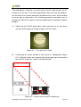
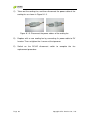


![USER Manual for WiFi edited5[1] - the Naples Free-Net](http://vs1.manualzilla.com/store/data/005874834_1-4f1e4f9158101a49e1c12c3e2f124ebe-150x150.png)