1
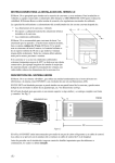
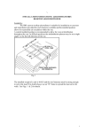
Aircommand Australia Pty Ltd
OPERATING INSTUCTIONS
RHP SERIES 1800 CARAVAN AIR CONDITIONER
General Hints
1. Ensure that flex coupling the caravan to the power outlet is rated at 15 amps
and is only as long as is reasonably necessary. Remember that voltage drop
occurs through the flex, and needlessly long flexes will reduce the output of
the air conditioner, and in some cases impede its correct operation.
2. Keep the inside filter clean by occasionally removing (tug out of recess) wash
in warm soapy water, and replace.
3. Maximum output is derived from the unit with the air control slide in the ‘MAX’
position, and the air deflectors fully open.
4. Strive to keep the ‘heat load’ on the caravan during summer to a minimum
by:
a) If possible park beneath shady trees
b) Use awnings over windows
c) Draw curtains and blinds over windows
d) Close roof vents etc.
e) Avoid use of stoves where possible during peak of day
To operate on Cooling Cycle
1. Ensure power is turned on.
2. Depress ‘Cool’ button (blue).
3. Turn Black thermostat knob to mid position from ‘off’. Fan will start
immediately, and if room temperature is over approximately 25°C,
compressor will start, and cooling air will be apparent within 1 minute.
NOTE
For lower inside temperatures, turn the knob in the direction of ‘
‘Cooler’. The minimum inside temperature the thermostat
will allow I
is 19-20°C.
The fan will run continuously, and the thermostat will turn the compressor on
and off in response to return air temperature. For nighttime use, the air
volume slide may be moved to ‘MIN’ to reduce air noise. This however, does
reduce the cooling capacity of the unit.
To operate on Heating Cycle
1. Ensure power is turned on.
2. Depress ‘Heat’ button (red).
3. Turn Black thermostat knob to mid position from off. Fan will start
immediately, and if room temperature is below approximately 24°C,
compressor will start and heating air will be apparent within 1 minute.
NOTE
For lower inside temperature, turn knob in direction of ‘Cooler’. For
h
higher inside temperature, turn knob in direction of ‘Warner’.
On very cold nights, the air control should be moved to ‘MIN’ to increase the
temperature of the out coming air, even though the volume will be reduced.
INSTALLATION
General Comments
1. The Aircommand R.H.P. is designed to be installed in a 14” x 14” square
hatch (355mm x 355mm).
2. The unit should be level or laying back no more than 5°. The unit must
not lay forward. N.B.
The plastic nose is regarded as the front of
the unit and the outside coil the rear.
3. As the unit weights 55kg, reinforcing is generally necessary to strengthen
the roof.
4. Electrical requirements call for a 15 amp fuse serving the unit. Any flexes
should be kept to a minimum length and be rated 15 amp cable.
Reinforcing
1. Internal Reinforcing:
This is normally supplied ex the caravan manufacturer, and will normally
consist of steel sections bolted to the roof cross members. Installation of
internal reinforcing in existing caravans is usually very costly, as the roof
will need to be unfastened and rolled back to allow 25 x 25 x 4 angle to be
bolted to the members over which the airconditoner will lie.
2. External Reinforcing:
This is the preferred method for existing vans, and should be fabricated as
per figure 1.
Installation Procedure
1. Select a suitable place to cut a 355 square hole or utilise an existing hatch
opening of this size.
2. If cutting a new hole, ensure that it lies between existing roof members if
possible.
3. Having cut the hole, the electrical cable should be installed. Depending upon
electrical supply authority requirements, either:
a) Install a new 15 amp weatherproof plug on the outside of the van directly
in line with the hole.
b) Wire across the ceiling space and connect into existing fuse or circuit
breaker. Install an isolating switch approximately 150mm from the edge
of the hole, and bring the cable out leaving 300mm handing out.
4. Now box up around the hole using timber minimum 25mm thick.
5. Lay down a generous bead of silicone sealant around the hole.
6. Now carefully lay the ‘H’ frame over the hole.
7. Lift unit onto roof and then place onto ‘H’ frame. Slide the rear support rail
beneath tail of unit.
8. Now, from inside the van, line the unit up directly over the frame and the
frame directly over the hole.
9. Wire up power supply cable to terminal box.
10. Undo elastic band from control flex and leg hand down.
11. Carefully measure the distance from the underside of the unit to the
underside of the ceiling. Deduct 8mm from this measurement and proceed to
trim the clear plastic extension duct to this length. (Trim the plain end and
leave the flanged end).
12. Reach up and close the entry duct by pushing damper control lever
backwards. (This is necessary to allow the front hold down bolts to pass
behind the damper and avoid interfering with it’s operation).
13. Prepare the 4 hold down bolts by slipping on the 3 large clamp plates, and 1
short clamp plate.
14. The duct extension handle should now be slid onto the damper control rod,
and it’s length adjusted such that 65mm (including thread portion) hangs
below ceiling line.
15. Place the duct extension onto the upstanding flange of the base plate
assembly and lift up against the ceiling, passing the damper extension arm
through the slot in the base plate.
16. Referring to Figure 3, base bolts A & B can be inserted through the respective
holes in base plate, and screwed into the tapped plates in the corner of the
unit. Bolts C & D do not pass through assembly holes in the base plate, but
when tightened up, the clamp plates secure the reinforcing angles of the
plate.
17. When all bolts are engaged and lightly done up, the 2 resilient feet should be
attached to the square tubular side rails of the chassis in position indicated in
Figure 2.
18. Now, finally tighten the 4 hold down bolts, observing the following:
a) Ensure extension duct covers the fan outlet
b) Ensure that plate D is kept within the line of the side of the base plate to
avoid fouling the plastic plenum
19. With a silicon gun, seal the inside of the duct extension to the underside of
the unit, and likewise to the base plate. Ensure that no air leakage can occur.
20. Mate the breakway plugs on the control flex.
21. Fit plastic plenum up against base plate, and fit retaining knob.
22. Now screw in the 4 corner wood screws to pull up hard against ceiling.
23. Fit knob to threaded end of extension knob.