1
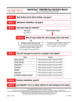
Oxygen & Carbon Dioxide Analyser Model 1737 Operators Manual January 2010 TABLE OF CONTENTS 1. Overview & Specifications .............................................................................................. 3 1.1 Hardware Specifications .......................................................................................................................... 4 1.2 Product & Logging Specifications ............................................................................................................ 5 1.3 Cabinet ..................................................................................................................................................... 6 1.4 Display ..................................................................................................................................................... 7 1.5 Keypad ..................................................................................................................................................... 9 2. Quick Start .................................................................................................................... 11 2.1 Turning on the 1737 ............................................................................................................................... 11 2.2 Taking a Reading ................................................................................................................................... 11 3. Setting Up the Analyser ................................................................................................ 13 3.1 Setup Menu ............................................................................................................................................ 13 3.2 Calibration Menu .................................................................................................................................... 14 4. Alarms........................................................................................................................... 17 4.1 Sample Gas Related Alarms .................................................................................................................. 17 4.2 Hardware Alarms ................................................................................................................................... 17 5. Bluetooth PC Interface .................................................................................................. 19 5.1 Pairing Bluetooth Devices ...................................................................................................................... 19 5.2 PC Interface Software ............................................................................................................................ 20 6. Calibration ..................................................................................................................... 21 6.1 Oxygen ................................................................................................................................................... 21 6.2 Carbon Dioxide ...................................................................................................................................... 22 7. Batteries........................................................................................................................ 23 7.1 Charging the Batteries ........................................................................................................................... 23 7.2 Battery Running Time ............................................................................................................................ 23 7.3 Battery Display Indication ...................................................................................................................... 24 8. Maintenance ................................................................................................................. 25 8.1 Analyser Information Screen.................................................................................................................. 25 8.2 Replacing an Oxygen Sensor / CO2 Lamp Source & Sensor ................................................................ 26 8.3 Upgrading the Firmware in the Analyser ............................................................................................... 27 8.4 Changing the Batteries .......................................................................................................................... 28 9. Troubleshooting, FAQ .................................................................................................... 29 January 2010 1737 O2 & CO2 Analyser Operators Manual 1 Copyright NOVATECH CONTROLS PTY LTD — 2009 This manual describes firmware version 1.24, December 2009 Neither the whole nor any part of the information contained in, or the product described in, this manual may be adapted or reproduced in any material form except with the prior written approval of Novatech Controls Pty Ltd (Novatech). The product described in this manual and products for use with it are subject to continuous developments and improvement. All information of a technical nature and particulars of the product and its use (including the information in this manual) are given by Novatech in good faith. However, it is acknowledged that there may be errors or omissions in this manual. A list of details of any amendments or revisions to this manual can be obtained upon request from Novatech Controls Technical Enquiries. Novatech Controls welcome comments and suggestions relating to the product and this manual. All correspondence should be addressed to: Technical Enquiries Novatech Controls Pty Ltd 309 Reserve Road, Cheltenham Victoria 3192 Australia Tel: Fax: Email: Website: +61 3 9585 2833 +61 3 9585 2844 [email protected] http://www.novatech.com.au/ Novatech Controls or their authorised dealers should carry out all maintenance and service on the product. Novatech Controls can accept no liability whatsoever for any loss or damage caused by service or maintenance by unauthorised personnel. This manual is intended only to assist the reader in the use of the product, and therefore Novatech Controls shall not be liable for any loss or damage whatsoever arising from the use of any information or particulars in, or any error or omission in, this manual, or any incorrect use of the product. Operators Manual 2 January 2010 1737 O2 & CO2 Analyser 1. OVERVIEW & SPECIFICATIONS The 1737 analyser is an instrument for measuring oxygen and carbon dioxide concentration in a sample of gas. It has been designed for use in the food packaging industry where products are packaged in a modified atmosphere of nitrogen and/or carbon dioxide. Gas is extracted from the packaging via a sample line fitted with a hypodermic needle. The needle is used to penetrate the food packaging and an internal pump draws the package atmosphere into the analyser to be measured. The 1737 has several key features that offer the user distinct advantages over other gas analysers. The oxygen sensors can be tailored to suit the needs of the user The oxygen sensors are not wet electrolyte type so will not age The oxygen sensors are field replaceable An optional internal battery can be supplied allowing up to 1 hour continuous operation without mains power. It has a large clear display All samples are stored to an internal log that can be easily reviewed by the operator It can be configured to read and log the samples based on a series of product requirements Samples can be uploaded to a computer using wireless technology Automatic calibration is done whenever the sample is coming from air Extended CO2 calibration is an automatic display driven process The 1737 can be supplied in several different orientations; Model # 1737-1 1737-2 1737-3 Oxygen range 0.1% to 25% 30ppm to 25% 0.1% to 96% CO2 range Not installed Not installed Not installed 1737-1C 1737-2C 1737-3C 0.1% to 25% 30ppm to 25% 0.1% to 96% 0 to 100% 0 to 100% 0 to 100% January 2010 1737 O2 & CO2 Analyser Operators Manual 3 1.1 Hardware Specifications Oxygen range 1737-1 1737-2 1737-3 0.1 to 25% 100ppm to 25% 0.1 to 96% Oxygen accuracy Oxygen (25-96%) Oxygen (10-25%) Oxygen (0.4-10.0%) Oxygen (100-1000ppm) +/- 0.5% +/- 0.05% +/- 0.01% +/- 30ppm Oxygen display resolution 30.0 to 96.0% (1737-3) 1.00 to 29.99% 100 to 10,000ppm (1737-2) 0.1 to 99.9ppm (1737-2) +/- 0.1% +/- 0.01% +/- 1ppm +/- 0.1ppm CO2 range 1737-x 1737-xC CO2 not installed 0 to 100% CO2 accuracy 0 to 40% 40 to 80% 80 to 100% +/- 2% +/- 3% +/- 5% Gas flow rate Normal flow Small sample flow Minimum / Maximum flow 150cc/m 80cc/m 10 / 400cc/min Gas volume (to 10% of the final reading) Normal flow (150cc/m) Oxygen only, 1% to 10% Oxygen only, 100 to 1,000ppm Small sample flow (50cc/m) Oxygen only, 1% to 10% Oxygen only, 100 to 1,000ppm 30cc 90cc 15cc 40cc Gas connection 1/8‖ Swagelok Communications Bluetooth wireless Power Requirements Voltage 12 VDC Current (maximum) With batteries Without batteries 1.8A 0.8A Power (maximum) 22 watts Warm up time 1 Minute Environmental Ambient temperature Ambient humidity IP rating -20 – +35 10 – 90% non-condensing IP54 Compliance Operators Manual 4 yet to be certified January 2010 1737 O2 & CO2 Analyser Battery capacity ~1 hour operation (1737-1C) Size 280L x 180W x 115H Weight, Analyser Weight, Power pack 2.0kg 0.5kg Accessories Filters Sample line Carry case 1.2 Product & Logging Specifications Number of products stored 200 maximum Product name ~22 characters (alpha-numeric and symbols) Exact number of characters is limited by the width of the display and will vary. Log memory capacity 3,696 oxygen / CO2 readings January 2010 1737 O2 & CO2 Analyser Operators Manual 5 Power socket, Battery charger 1.3 Cabinet Sensor access lid Display Needle holder Sample gas inlet Keypad Display The 1737 display is a 192x64 pixel monochrome graphical LCD that can show multiple font sizes and symbols. In standard operation it shows the current oxygen and carbon dioxide readings, previous sample readings, alarm status, battery charge remaining and gas flow rate. Keypad Used for product and analyser configuration. Sample Gas Inlet Sample line is attached to this 1/8‖ coupling. Needle Holder Safe storage for the hypodermic needle when it is not in use. Sensor Access The rear cover can be removed by removing the 2 screws on the back of the cabinet. The oxygen sensor(s) can then be accessed for replacement. Power Socket External 12VDC input to power the analyser and charge the batteries. Operators Manual 6 January 2010 1737 O2 & CO2 Analyser 1.4 Display Battery charge indicator Oxygen current reading Gas flow rate indicator (0-300cc/min) O2 2.03% 20.95 Mains power and rapid charge indicator CO2 31.5% 0.0 160 001.Product 001 (1/5) Gas flow rate CO2 current reading Oxygen sample CO2 sample Product number Product name Products to be tested Battery Charge Status The battery charge indicator gives an approximate status of the battery power level. When the expected run time falls below 5 minutes the status bar and the battery symbol below the charge status bar will flash. Oxygen, Current Reading The large figures on the oxygen side of the display will show the current oxygen measurement. Oxygen, Sample Reading The small figures on the oxygen side of the display will show the last gas sample taken. When a new sample is being taken the previous sample will be removed and the oxygen sample will remain hidden until the sample in progress is completed Mains Power and Rapid Charge Indicator The mains power indicator will display a power plug symbol when the plug pack adapter is present and a battery symbol when no external power is present. The plug symbol will be filled in when the batteries are on rapid charge. For more details refer to Chapter 7: Batteries Product Number This is the number of the currently selected product. If ―Product Selection‖ has not been enabled in the setup menu #1, the current date and time will be shown. Product Name This is the description that has been entered for the currently selected product. Products to be Tested This a counter that can be used when testing in multiple sample batches. The first number is the current sample number and the second number is the total number of samples to be tested in the batch. CO2, Current Reading The large figures on the CO2 side of the display will show the current CO2 measurement. January 2010 1737 O2 & CO2 Analyser Operators Manual 7 CO2, Sample Reading The small figures on the CO2 side of the display will show the last gas sample taken. When a new sample is being taken the previous sample will be removed and the CO2 sample will remain hidden until the sample in progress is completed. Gas Flow Rate This is the sample gas flow rate displayed in 10cc/min steps, as measured by the internal flow sensor. The number will flash if the flow falls below 80cc/min and the ―Sample Line Blocked‖ alarm will be triggered if the analyser is unable to achieve its automatically set flow rate. Gas Flow Rate Indicator The gas flow indicator shows the sample flow rate on a scale of 0-300cc/m. The flow can be set in the calibration menu but will normally be around the central mark of 150cc/m. Operators Manual 8 January 2010 1737 O2 & CO2 Analyser 1.5 Keypad Power Standby on/off O2 2.03% 31.5% 20.95 Product Selection & edit Display / accept alarms CO2 0.0 160 001.Product 001 (1/5) Display sample log Change value Up / Down Product batch reset counter Manually calibrate the gas sensors Enter, Accept and Setup mode Power The power key turns the analyser on or off depending on its current state. If external power is connected the batteries will continue charging even when the analyser is switched off. Product A short press of the key will bring up the ―Product List‖ to enable the current product to be changed. Pressing and holding the key for 2 seconds will bring up the ―Product Edit‖ menu. A short press while in the either the Product List or in the Product Edit will take the analyser back to the main screen. Log A short press of the key will show the ―Data Log Summary‖ of all the samples that have been taken. Up / Down These two keys are used to change a selection or a value. January 2010 1737 O2 & CO2 Analyser Operators Manual 9 Enter The enter key is used to confirm a selection. A short press of the key from the analyser main screen will enter the setup menu. For more details see Chapter 3.1: Setup Menu. Calibrate Pressing the key for 2 seconds will bring up the calibration menu. Use the up/down keys to select the type of calibration required. For more details see Chapter 6, Calibration. Batch Reset Pressing the key for 2 seconds will reset the product batch counter. Alarm In the event of an alarm being triggered, the alarm LED will flash and the analyser will beep to alert the operator. There are 2 different types of alarms – Sample Gas alarm A message will be displayed on the screen explaining the cause of the alarm. Press the alarm key and the message will disappear. The alarm LED will go off. Hardware alarm A message will be displayed on the screen explaining the cause of the alarm. Press the alarm key and the message will disappear but the alarm LED will stay on until the source of the alarm has been resolved. If the alarm LED is on (not flashing) pressing the alarm key will show the list of current hardware alarms. Operators Manual 10 January 2010 1737 O2 & CO2 Analyser 2. QUICK START 2.1 Turning on the 1737 Press the key on the top left hand corner of the 1737 analyser to turn on the power. The display will light up and show the Novatech company logo along with software version and product serial number. The oxygen and carbon dioxide sensors inside the analyser take approximately 60 seconds to reach operational temperature and stability, therefore gas readings will not be shown immediately. When the analyser is ready to sample it will alert the operator with a single beep. The 1737 can be run from either the power pack or from the internal batteries. If the display does not light up immediately after pressing the power key, plug in the power pack and try again. The batteries will need up to 3 hours to fully charge and the analyser can be run while the batteries are being charged. 2.2 Taking a Reading After the power has been turned on it will take approximately 60 seconds to see a reading on the display. Once the readings appear measurements can be taken. The display will show the oxygen and the CO2 readings in the large characters. It also has a bar graph on the left to show the state of the batteries (if installed) and a bar graph on the right to show the sample gas flow rate. If the analyser has been on for more that a minute and the sample line is in air, the display will show the oxygen measurement as 20.95% and the CO2 as 0.0%. A good way of checking the CO2 calibration of the analyser is to have a bottle of certified gas of 30% CO2 in nitrogen on site. Use a pressure regulator and a needle valve to control the gas flow to about 300cc/m. Insert the sample needle about 2 centimetres into the exhaust hose from the gas bottle. The oxygen reading should go down to at near 0.1% (this depends on what range of oxygen sensors are installed) and CO2 reading should go up to 30%. For more detailed information regarding the operation of this analyser, refer to the table of contents and read the specific chapters. January 2010 1737 O2 & CO2 Analyser Operators Manual 11 Operators Manual 12 January 2010 1737 O2 & CO2 Analyser 3. SETTING UP THE ANALYSER Operation of the Menu System The configuration of the analyser is modified via a keypad driven menu system which is accessible whenever the analyser is idle (not taking a sample). Each menu is numbered in the top left corner and has a brief description of what functionalities it controls. The menu itself will then have up to 4 individual items shown in a list below and on the left hand side a cursor symbol ‗>‘ which indicates which item is currently selected. The keypad uses four keys to navigate through and modify items; the up/down, enter and log. As a guide, the up/down keys move the cursor up and down and change a value, enter is used to select the item pointed to by the cursor and log is used to step backwards and un-select the currently selected item. To make changes to an item in the setup menu, navigate through the menus with the up/down keys, using enter to firstly select the menu you wish to enter, then again to select the item in the list below. The item being modified will then be highlighted and the up/down keys will modify its value. To save changes to the item being edited, finish by pressing enter, or to return to the menu without saving changes press log. Once finished, exit the setup menu by pressing the log key Below is a list of options accessible from the setup menu, the default after a factory reset is indicated in bold. 3.1 Setup Menu To access the setup menu press enter from the main screen. 01. Analyser Options Auto Power Off Time The analyser can turn itself off automatically if there been no measurement taken and no key pressed for a specified period of time. Options Disabled / 5 mins / 15 mins / 30 mins / 45 mins / 1 hour / 2 hours Pump Power Off The analyser can turn off the sample pump if there has been no measurement taken and no key pressed for a specified period of time. Options 15 seconds / 30 Seconds / 60 Seconds / 2 mins / 5 mins / 15 mins / 30 mins / Always On Analyser Mode Select either Sample + Hold or Continuous. Continuous mode is only used if the analyser is to be permanently connected to the gas stream to be measured. Product Selection Enable and Disable the product selection system which can be used to describe the samples being logged, set automatic alarm thresholds and group samples into batches. When Products are enabled with this option the analyser will use the appropriate alarm levels that were preset using the Product Edit function. For more details see Chapter 3.2: Products. 02. Sample Gas Alarms This menu is made available when product selection is disabled. When product selection is enabled these alarm levels are overridden by those defined by the selected product. High Oxygen Alarm / Low Oxygen Alarm High CO2 alarm / Low CO2 alarm Triggers a sample gas alarm when the oxygen/CO2 sample level is above the high alarm level threshold, or below the low alarm level threshold. January 2010 1737 O2 & CO2 Analyser Operators Manual 13 3.2 Calibration Menu The calibration menu is a second semi-hidden menu system in the analyser that contains a series of device calibration and configuration options. It is not intended that the operator should have to modify this menu unless performing more advanced changes to the instrument or re-calibration. Modification of items in this menu may affect the calibration and operation of the device and anybody intending to modify these values should make note of the previous saved values before performing changes should they wish to change them back. To access the calibration menu press and hold enter for 3 seconds from the main screen. 01. Input Calibration The voltage references represent a series of fixed gain ranges available to the internal analogue to digital converter used to measure oxygen. These voltage references are set at the factory to fine tune the ADC for accurate input measurement and do not require adjustment unless the device calibration has been lost due to a ‗cold start‘ or ‗master reset‘. The four references can be read using a meter on the four reference test points inside the analyser, their values are entered into this menu. Reference 1: Approx. 8mV Reference 2: Approx. 90mV Reference 3: Approx. 890mV Reference 4: Approx. 2490mV 02. Internal Clock Date & Time Date & Time This sets the internal clock date & time for the analyser. The internal clock is used to timestamp samples being recorded in the internal sample log. NOTE: The internal clock is able to maintain accurate time without external power or batteries for many years. Daylight Savings By enabling this option the internal clock is automatically advanced one hour. This makes adjusting backwards and forwards for daylight savings time easier to perform. 03. Installation Options CO2 Cell This option should be set at the factory depending on whether there is a CO2 cell present in the analyser. Internal Battery This option enabled and disables the battery indicator and power saving functions associated with battery powered operation. Bluetooth This option enables the start-up initialisation and runtime communication with the Bluetooth module option in the analyser. If the Bluetooth module is not present this option should be set to disabled. Pump Type The analyser may be fitted with one of two types of sample pump. This will be set correctly at the factory and will not need to be changed unless the pump is changed. 04. Sample Pump Control Flow Control The flow control can be set to either Automatic flow control or Manual flow control. Automatic flow control uses an internal flow sensor and adjusts the sample pump voltage to achieve a specified flow rate. Flow Rate Visible when flow control is set to Automatic, set the automatic flow rate between 40-250cc/min (default is 150cc/min) If Manual was selected as the Flow Control, the Flow Rate setting will change to Pump Voltage. CO2 Factor This factor improves the accuracy of the flow reading when the sample gas has a high level of CO2. Operators Manual 14 January 2010 1737 O2 & CO2 Analyser 05. Oxygen Sensor Options Extended Display Used primarily for troubleshooting the ‗extended display‘ changes the standard runtime display of the analyser to show the sensor millivolts for the oxygen and carbon dioxide sensors. It is not recommended that you enable this option for ordinary sample and hold measurement. Oxygen Cell 1 / Oxygen Cell 2 This option enables/disables the respective oxygen cells. By disabling a cell you effectively remove this cell from potential oxygen calculations and turn off power. This may be useful if a cell has failed or in specialised cases to extend battery life of the analyser. 06. Oxygen Cell 1 Calibration PPM Span Gas Visible when a PPM cell is present. Set this to match the gas used for calibrating the oxygen ppm sensor. Range 800 – 1200ppm (default is 1000ppm) Cell Offset This offset corrects for the variance in fixed offset between different oxygen cell modules at the low extremity of their functional range of measurement. It is set during factory calibration and should not be changed unless a cell is being replaced. Cell Calibration Each oxygen cell will have an output in the range of 400 to 800 mV when it is exposed to air. This level is set automatically when the calibration button is pressed, or it can be set manually with this option. 07. Oxygen Cell 2 Calibration Cell Offset This offset corrects for the variance in fixed offset between different oxygen cell modules at the low extremity of their functional range of measurement. It is set during factory calibration and should not be changed unless a cell is being replaced. Cell Calibration Each oxygen cell will have an output in the range of 400 to 800 mV when it is exposed to air. This level is set automatically when the calibration button is pressed, or it can be set manually with this option. Low Oxygen Cal This figure fine adjusts the 0.1 – 25% oxygen cell for natural variation in full scale linearly between difference cells. It is set during factory calibration and should not be changed unless the 0.1 – 25% oxygen cell is being replaced. 08. CO2 Signal Tuning CO2 Gain / CO2 Offset These two figures are automatically calculated and set via the ‗Set CO2 Zero & Span‘ calibration option. Changing these values will invalidate the CO2 readings and these numbers are supplied in this menu more for informational purposes than for editing. It is NOT recommended that these factors are ever changed manually. Lamp Duty Cycle This factor is used to report how the automatic CO2 calibration has configured the lamp driving circuit. It is NOT recommended that these factors are ever changed manually. 09. CO2 Calibration The Zero Counts, Span Counts and the Cal Temperature allows a technician to read the factors that are used to set the calibration of the CO2 measurement. It is NOT recommended that these factors are ever changed manually. 10. CO2 Mid Gas Calibration CO2 Mid Cal Gas Visible when the CO2 cell is installed. Set this to match the gas used for mid scale CO2 gas calibration. Range 20.0 to 60.0% (default is 30.0%) January 2010 Operators Manual 1737 O2 & CO2 Analyser 15 CO2 Mid Cal Adjustment After the Mid Gas Calibration has been performed, the calibration adjustment figure that is used to trim the CO2 reading is shown here. It is not recommended that this factor is ever changed manually. 11. Memory Reset NOTE: Please use the items in this menu with caution as the actions performed are NOT reversible. Reset Internal Log The internal sample log is cleared. Reset Products All products will be set back to their factory defaults 3.3 Products 3.3.1 Product Selection Summary The 1737 analyser operates as a gas analyser to measure the oxygen and the CO2 in a gas sample, displaying and holding these readings. It also maintains a record of all samples taken and can upload the records to a computer using Bluetooth wireless communication. To improve the logging and reviewing of samples taken by the analyser, the product selection feature has been included to allow the operator to define individual ‗products‘. These products can be as simple as a meaningful description for what is being sampled, or can be more detailed to include alarm thresholds for both oxygen and CO2 as well as batch sample counting to allow grouping of samples in the internal log. To be able to use this feature ‗Product Selection‘ must be enabled in Setup menu 1 Once enabled, the operator can press the product key on the keypad to bring up a list of available products. To select a product from the list use the up/down keys to move up and down and press enter to select the highlighted product and exit the menu. To exit the menu without making a selection, press the product key 3.3.2 Creating and Editing Products By default five basic products are made available when product selection is enabled, however to make full use of the product selection functionality the products must be defined in accordance with the requirements of the operator. To access the product editing menu, press and hold the product key for 2 seconds until a second beep and ‗editing products‘ is displayed. The product edit menu operates similarly to the product selection menu using the up/down keys to move through the list and enter to select the highlighted product. On selection of a product a new product editing menu is shown where the up/down, log and enter keys are used the same as in the setup menu. Editing of the product description requires the use of the alarm and batch reset keys to move the cursor backwards and forwards. The up/down keys change the underlined character and the number of characters available in the description is bound by a maximum of 22 characters, or the edge of the display. To return to the list of edit products, and to return to the main screen once product editing is complete, press the log key Operators Manual 16 January 2010 1737 O2 & CO2 Analyser 4. ALARMS The 1737 alarm system incorporates both hardware and sample gas alarms and uses the display, a flashing alarm LED and the internal beeper to alert the operator when it requires attention. When an alarm is triggered the alarm LED on the front of the case will flash, a single beep will be emitted and a short description of the alarm will appear on the display. If the reason for the alarm is a sample gas reading outside of the defined alarm conditions then the operator acknowledges the alarm by pressing the alarm key to clear the alarm and ready the analyser for any new samples. Sample gas alarm checks occur at the completion of a gas sample. Hardware related alarms will trigger any time the analyser detects a problem. The difference however is that hardware alarms do not clear once acknowledged by the operator and will remain active until the condition causing the alarm is resolved. When a hardware alarm is acknowledged the alarm LED stops flashing but remains lit. By pressing the alarm key again a list of active hardware alarms is displayed. 4.1 Sample Gas Related Alarms The alarm parameters for the sample gas alarms are either set in the setup menu when product selection is disabled, or via the product editing features described in Chapter 3.1. When a sample is completed and the oxygen & CO2 readings have been recorded the new sample readings are checked against the alarm parameters. High Oxygen The oxygen measurement in the last sample is above the high oxygen alarm threshold. Low Oxygen The oxygen measurement in the last sample is below the low oxygen alarm threshold. High CO2 The CO2 measurement in the last sample is above the high CO2 alarm threshold. Low CO2 The CO2 measurement in the last sample is below the low CO2 alarm threshold. 4.2 Hardware Alarms The analyser constantly monitors many aspects of its operation and will quickly detect any faults. These alarms are related to the operation of the hardware and will vary from being easily fixed by the operator through to a serious hardware failure requiring technical assistance or repair. For information on replacement of parts within the analyser refer to Chapter 8: Maintenance. The Following alarms indicate faults that may be possible to perform repairs on-site using replacement parts. If however if there is any doubt please return to the manufacturer for service. Oxygen Cell 1/2 Error The analyser has detected that either the heater in the specified oxygen cell has failed or the sensor has failed to reach a stable level within 2 minutes after turning the power on. Follow the procedure in chapter 6.1.1, Oxygen calibration in air, to attempt to recover the oxygen cell(s). If the error remains the oxygen cell(s) may require replacement. January 2010 1737 O2 & CO2 Analyser Operators Manual 17 CO2 Sensor Error This error occurs when the CO2 cell is unable to detect a signal within range. It will occur either when the CO2 sensor physically fails, or if the calibration of the CO2 cell has been affected and is reading saturated readings. If re-calibrating the CO2 cell does not fix the problem then the CO2 sensor may require replacement. CO2 Lamp Error The CO2 lamp has failed. The lamp can be changed through the sensor access cover. See chapter 8.2, Replacing the CO2 Lamp Source & Sensor. Sample Pump Error Very low or no current is being drawn by the sample pump. This alarm most likely means the physical connection to the sample pump has been broken or the sample pump itself has ceased working. The pump may require replacement to resume operation. Sample Pump Overload Excessively high current is being drawn by the sample pump and it has been disabled to prevent any serious damage to the analyser hardware. Replacement of the sample pump will be necessary to resume operation. Sample Line Blocked The sample pump is unable to achieve its desired flow, likely caused by a blockage in the sample line. Remove and inspect the sample line carefully for blockages, replace if necessary. If the alarm is still active with the sample line removed then the blockage is inside the analyser and will require appropriate repairs to be carried out to clear the blockage. NOTE: Do not attempt to clear an internal blockage using compressed air from either the input or exhaust port on the analyser. Doing so could easily cause permanent damage to the sample pump, flow, oxygen and CO2 sensors. Battery Charge Error The batteries have been charging for more than 2 hours without retaining any level of charge. Running from batteries may not be possible and the batteries may require replacement. The following alarms indicate faults that will require return to manufacturer for service. Flow Sensor Error The flow sensor used to automatically control the sample pump has failed. It may be possible to run the sample pump at a manually set voltage to continue sampling in the interim before repair. Internal BBRAM error The configuration memory or real time clock on the main PCB has failed. This will instantly render the device un-calibrated and it should be returned for service and re-calibration. Do not use the analyser if this alarm is present as the sample readings will be incorrect. Internal Memory Error The internal flash memory for storing the sample log has failed. The data logging functionality will not be working, however sampling of oxygen and CO2 will not be affected. ADC Hardware Check Fail The analogue to digital signal converter has failed to calibrate correctly. Do not use the analyser if this alarm is present as the sample readings will be incorrect. Bluetooth Error The Bluetooth module on the main PCB has failed. Wireless communications is disabled. Operators Manual 18 January 2010 1737 O2 & CO2 Analyser 5. BLUETOOTH PC INTERFACE The 1737analyser has an optional Bluetooth interface allowing it to wirelessly interface with Bluetooth enabled PCs. Via Bluetooth the analyser is able to perform tasks such as configuration of products & alarm thresholds and transferring the contents of its internal sample log enabling it to be easily viewed and manipulated in popular spreadsheet programs such as Microsoft® Excel™. The PC Interface software for Microsoft® Windows™ is supplied with the purchase of a Bluetooth enabled analyser or free by download at the Novatech Controls website http://www.novatech.com.au/ Operating System Requirements for supplied software: Microsoft® Windows™ XP SP1 or newer* Bluetooth 1.1 compatible adapter * tested and confirmed working on Windows XP SP1-SP3, however will most likely work on previous operating systems from Windows® 98 upwards. At this stage there is no intention on the behalf of the manufacturer to produce software for any other operating systems. If you wish to produce your own software for use on other platforms details of the communications stack and protocols will be made available by reasonable request. 5.1 Pairing Bluetooth Devices Before starting the program and communicating with your analyser for the first time you must first pair the analyser and the computer using the Windows Bluetooth Devices wizard. Some steps below may require Administrator privileges to perform. Turn on the Bluetooth enabled analyser you wish to communicate with. From Windows, open the Control Panels and locate and open Bluetooth Devices: Click the Add button to add a new Bluetooth device. Check the box on the next window stating ‗My device is set up and ready to be found‘. Click Next After a brief delay a box will showing all nearby Bluetooth devices will appear. If your device does not appear in the box you can click search again to repeat the process. The Novatech Controls 1737 analysers should be recognisable as blue icons with the name NTC1737_NS#xxxxx‘ where x is replaced with the device serial number. Select the analyser and click next In the next window asking for a passkey, select the second radio button from the top ‗Use the passkey found in the documentation‘. The passkey for all analysers is novatech (all lower case). Click next If successful Windows™ will now complete the process of pairing your Bluetooth device and setting up appropriate RFCOMM serial port connections to allow the software to communicate with the device. Click finish to close the wizard and close the Bluetooth Devices Control Panel January 2010 1737 O2 & CO2 Analyser Operators Manual 19 5.2 PC Interface Software The PC interface software does not require any installation and consists of a single small Windows executable file. The program is designed to be as straightforward as possible in its job to allow easy editing of sample products, and for transferring the items in the sample log. There is one main screen consisting of three boxes, some basic device information and a single row of buttons along the right side. The top box lists all discovered analyser devices, the middle box the products that are defined in that analyser, and the bottom box lists sample log items. On start-up the program automatically begins searching for 1737 analyser devices and lists the devices in the top box. When you select different analysers the information in the middle and bottom boxes should also automatically be loaded. The buttons on the right side are aligned to function in simple ways with the items directly next to them. Some further options may be accessed via popup-menus which appear when you right-click in one of the three boxes. To edit products you can either select the product to be edited and click the edit product button, or simply double click the product in the list. The editing product dialog box will be displayed to edit the product, click OK or Cancel to return to the main screen. The process of creating a new product is much the same as editing an existing product. You can have up to 200 individual products defined on the 1737 analyser. The sample log consists of a series of date stamped oxygen and CO2 measurements listed chronologically from most recent to oldest. The check boxes allow for individual selection and de-selection of sample log items for backup. To assist in selecting specific items to backup from the list there are buttons to automatically select and deselect log items based on their date and product type. Clicking backup exports all selected sample log items to a CSV (comma separated values) file which is able to then be imported into spread-sheeting programs for review. Operators Manual 20 January 2010 1737 O2 & CO2 Analyser 6. CALIBRATION The 1737 analyser is calibrated before leaving the factory and requires minimal ongoing re-calibration. After an initial factory calibration is performed, the oxygen cells are able to automatically compensate for drift caused by atmospheric variance by monitoring ambient air. The CO2 cell also compensates for drift by monitoring ambient air. However, it is more easily affected by temperature and humidity and will require occasional checking and annual re-calibration. To reach the calibration menu press and hold the calibrate key for two seconds until a beep is heard and the calibration menu appears. Use the up/down keys to move the cursor to choose the calibration option to be performed and press the enter key to select the option. To leave the calibration menu without making a selection press the calibrate key a second time. The first option is for calibrating oxygen cells, the second two for calibrating CO2. If the CO2 option is not installed in the analyser will assume the operator wishes to perform an oxygen calibration and bypass displaying the calibration menu. 6.1 Oxygen 6.1.1 Oxygen calibration in air There are three different ranged oxygen cells available for use in the 1737 analyser; a primary cell which has a response range of 0.1-25%, and an optional secondary cell which is scaled either 5-96% oxygen for enriched oxygen environments, or 100-1000ppm for accurate low oxygen readings. The first two cells are able to read and self-calibrate in ambient air, the low oxygen cell however requires the use of a certified 1000ppm ± 200ppm in nitrogen certified gas source. To force a calibration of either a 25% or 96% oxygen cell place the needle in ambient air and wait for 60 seconds to ensure a steady reading. Press and hold the calibrate key for 2 seconds to display the calibration menu and select the first option ‗Calibrate Oxygen‘ by pressing the Enter key. Follow the instructions on the display. The Batch Reset key may need to be pressed to acknowledge a message. The analyser will automatically select the cells to be calibrated based on their type and will alert on the display which cells have been calibrated. 6.1.2 Calibration of the ppm cell To calibrate a PPM cell you must have a 1000ppm ± 200ppm certified gas source. Before starting the calibration process ensure that the oxygen content of the calibration gas has been correctly entered in the Setup menu. Using a regulator set the gas source to approximately 500cc/min and place the sample needle inside the gas tube 20mm so that it is sampling directly from the gas source but not forcing the pressurised gas through the analyser. Wait for 60 seconds to ensure the analyser is reading a steady sample Without removing the sample needle from the gas source, press and hold the calibrate key for 2 seconds to display the calibration menu and select the first option ‗Calibrate Oxygen‘ Again the analyser will automatically select the cell to be calibrated based on cell type and alert on the display which cells have been calibrated. January 2010 1737 O2 & CO2 Analyser Operators Manual 21 6.2 Carbon Dioxide The CO2 calibration has two parts that can be selected from the calibration menu: Zero and Span calibration Mid Gas calibration The zero and span calibration is an automated process requiring a 100% CO2 test gas. It requires the cell to sample both 0% CO2 and 100% CO2 so that it can adjust the gain of its internal sensor to maximise reading resolution as well as physically calibrating the cell. After initial calibration the CO2 cell uses ambient air to track any minor drift that may occur due to temperature fluctuations. To perform a zero and span calibration start by preparing a 100% CO2 test gas bottle and regulator. Press and hold the calibrate key for 2 seconds to display the calibration menu and select the second option ‗Set CO2 Zero & Span‘ The display will prompt the operator to remove the needle from any CO2 source, allowing the analyser to sample ambient air. To continue press any key. When prompted to insert the needle into a 100% CO2 source. Use the regulator to set the 100% CO2 gas bottle to approximately 300cc/min and place the sample needle inside the gas tube 2cm so that it is sampling directly from the gas source but not forcing the pressurised gas through the analyser. Continue to follow the prompts and remove the needle when requested. Calibration will take a few minutes to complete and following a successful calibration numbers for CO2 sensor span and offset are displayed on the LCD and the analyser returns the main screen. Mid-gas calibration is performed to increase accuracy of the CO2 sensor in the specific region of the test gas. It is a single step calibration procedure which requires a certified CO2 test gas in the range of 20% - 60% CO2 in nitrogen. Before starting the calibration process ensure that the mid cal CO2 gas content of the calibration gas has been correctly entered in the Calibration menu. Using a regulator set the mid cal gas source to approximately 300cc/min and place the sample needle inside the gas tube 2cm so that it is sampling directly from the gas source but not forcing pressurised gas through the analyser. Wait for 60 seconds to ensure the CO2 sensor has a stable reading Press and hold the calibrate key for 2 seconds to display the calibration menu and select the third option ‗Calibrate CO2 x.x%‖ where x.x is the oxygen value of the certified gas. Once complete the mid gas calibration will immediately become active. It is recommended to test the calibration by immediately taking a fresh sample from the certified gas. Operators Manual 22 January 2010 1737 O2 & CO2 Analyser 7. BATTERIES To increase flexibility the 1737 has the option to install an internal battery pack allowing for up to an hour of operation without mains power. If the batteries are installed there will be a battery status bar displayed on the left hand side of the display. NOTE: Never leave the batteries in an uncharged state. The batteries will slowly self discharge even if the analyser is not being used. 7.1 Charging the Batteries The batteries will be charging as long as power is connected to the analyser. The analyser has two rates of charge; rapid charge and trickle charge. On rapid charge the batteries should be fully charged within 2 hours. The trickle charge is designed to maintain the current level of charge. For safety reasons the charge circuit is unable to rapid charge the batteries if they are too hot. To fully charge the batteries leave the analyser off and the power pack turned off for 2 hours then turn on the power pack but leave the analyser off for a further 2 hours. Once the batteries are fully charged, the charging circuit maintains maximum charge by trickle charging the batteries To monitor charging of the batteries there is a small icon at the bottom of the batter level indicator that changes to indicate status. When external power is present the glyph appears as a small two pronged plug. If the glyph appears as a solid block icon this means the batteries are on rapid charge, and as an outline means it is on trickle charge. NOTE: Whenever the analyser is running on batteries the batteries will heat up. If the analyser is then plugged into the power the batteries may not go on to the rapid charge mode until they have cooled sufficiently and the external power to the analyser is cycled off and then on again. 7.2 Battery Running Time The battery running time depends on several factors. Initial charge How many oxygen cells are installed in the analyser Ambient temperature Battery age and condition Generally the analyser will run for approximately one hour on the batteries if they have been fully charged. If the analyser is running on batteries and the remaining charge is very low the battery status bar will flash. If the batteries are not put on charge within a couple of minutes the oxygen sensor(s) will be turned off to conserve battery power (a ―-― symbol will be shown where the oxygen reading is normally). If the batteries are not put on to charge within 10 minutes the analyser will turn itself off. A flat battery will not cause loss of data from the sample log or reset the internal clock. January 2010 1737 O2 & CO2 Analyser Operators Manual 23 7.3 Battery Display Indication The display has a bar graph level indicator. This shows the approximate battery charge level when the analyser is running on batteries. If the analyser is running from the power the bar graph will be shown as having full charge and there will be a symbol of a power plug shown under the bar graph. If the charger is in rapid charge mode the power plug symbol will be solid, and in trickle charge mode the power plug will be an outline. When the time remaining for the analyser to run on batteries falls below approximately 15 minutes the battery symbol below the bar will flash. Battery charge level O2 2.03% CO2 31.5% 20.95 0.0 160 001.Product 001 (1/5) Battery symbol O2 AC power symbol (on trickle charge) 2.03% CO2 31.5% 20.95 0.0 160 001.Product 001 (1/5) For information on replacing the batteries see Chapter 8: Maintenance Operators Manual 24 January 2010 1737 O2 & CO2 Analyser 8. MAINTENANCE WARNING: Performing maintenance on the 1737 analyser will be outside of the scope of most operators. This information is provided as a reference only. Before attempting any repairs yourself carefully read all documentation and proceed with care. The 1737 is a delicate instrument that incorporates sensitive electronics and hermetically sealed sensors. Damage caused to the analyser during unauthorised repairs will not be covered by warranty. 8.1 Analyser Information Screen The 1737 has an information screen that can assist in the preliminary diagnosis of problems or simply provide additional information regarding the analyser. It is accessible via the keypad and does not affect the operation of the analyser making it ideal as a first point of reference should you suspect a problem. To access the information screen; from the main run screen press and hold the up & down keys together for approximately 1 second. Once the information screen appears, release the two keys. Navigate through the information screen using the up/down keys and exit back to the main screen by pressing enter. The screen shows the following information. Software version and serial number Calibration Date Current date and time Current ambient temperature and the maximum ambient temperature Current CO2 cell temperature and maximum cell temperature Reference voltages & ADC calibration information Oxygen cell types, sensor mV and calculated oxygen level Battery voltage Sample Pump Flow Rate Internal Memory Information Bluetooth Device Address & Status CO2 gain and offset January 2010 1737 O2 & CO2 Analyser Operators Manual 25 8.2 Replacing an Oxygen Sensor / CO2 Lamp Source & Sensor The oxygen sensors and CO2 lamp source in the 1737 are mounted in the rear of the analyser under the sensor access lid. In general use, it is not expected they should fail for many years. However, easy access has been designed into the analyser in the event of such a failure. If a failure occurs, the first thing to note is the hardware alarm which will indicate which cell has failed. Be aware that the CO2 sensor is mounted on the underside of the manifold requiring the complete removal of all cells and the gas manifold to access. If there is an alarm that indicates that a cell does need replacing, use the following instructions to replace the sensors Press the power key to turn the power off Remove the two screws from the rear of the cabinet Hinge up and lift out the sensor cover Determine which sensor is to be replaced. The hardware alarm will identify the cell. Oxygen Cell 1 Oxygen Cell 2 CO2 Lamp CO2 Sensor Remove the two screws that hold the circuit board. Note that the screws for the oxygen cells are different lengths. Be careful when removing or re-inserting the long screws as the captive nut on the chassis below can be easily damaged by pushing down on the screw. Carefully remove the circuit board taking care of the o-ring seal directly beneath the circuit board. Replace the cell with the new cell following the above directions in reverse To replace the CO2 lamp follow the above procedure. To replace the CO2 sensor, follow the steps above and remove BOTH oxygen cells and the CO2 lamp, then continue the steps below: Remove the vertically mounted circuit board that all three top boards were plugged in to. Un-screw the 1/8‖ Swagelok fitting that connects the oxygen cell to the sample line inlet. If you are experiencing difficulty in unscrewing this fitting from the sensor access lid it is possible to remove the front cover and (if installed) battery pack to gain access from inside the case. Please refer to the chapter 7.4 Replacing the Batteries for detailed instructions. Slide off the silicone tube from the other side of the cell block. Using a slight twisting movement. Carefully remove the cell block from the analyser After an oxygen cell has been replaced it may be necessary to perform an O2 calibration. After a CO2 lamp or CO2 sensor has been replaced it will be necessary to perform a CO2 calibration. Please refer to Chapter 6 for further information regarding calibration. Operators Manual 26 January 2010 1737 O2 & CO2 Analyser 8.3 Upgrading the Firmware in the Analyser The firmware for the 1737 analyser is stored in flash memory inside the microprocessor. The analyser therefore does not require an external memory IC to operate. Provision has been made to enable the firmware to be upgraded in the field WITHOUT the use of a computer. If an upgrade is to be made to the firmware it will be supplied in a 32 pin EEROM IC type 29F010B. To do the upgrade, use the following steps: Turn the power off to the analyser at the power key Unplug the power plug at the back of the analyser Remove the cover strips from each side of the analyser lid Undo the 4 screws that hold the lid to the body of the analyser Carefully lift up the lid. There is a cable that connects the display PCB to the main PCB. Fold out the two wings of the socket labelled ―FIRMWARE UPGRADE SOCKET‖. Plug the 29F010B into the socket. Carefully note the direction of the IC. Pin 1 is identified on the PCB and pin 1 on the IC has a small round indentation next to the pin. Press and hold down the log and enter keys and then press the power key Release the keys when the message ―Verifying the EEROM‖ is shown. The analyser is confirming that the new firmware is valid. After the EEROM has been read and confirmed this message will be shown: Upgrade Firmware? Model 1737 New Version: 1.## Upgrade Cancel Press the product key to ‗Upgrade‘ the firmware. Press the batch reset key to cancel the upgrade and continue the start up of the current firmware. Upgrading Firmware. Analyser will reset itself in approx. 30 seconds. Do not turn off the power NOTE: While the firmware is being upgraded it is essential that the power is not turned off otherwise the programme will be corrupted and will not be recoverable. When the analyser has upgraded the firmware it will start up the normal initialisation. The version of the firmware is shown on the start up screen. Turn the analyser power off. Unplug the EEROM by pressing out the wings of the blue upgrade socket. Keep the EEROM in a safe place. It can be used to upgrade any number of analysers as required. Replace the lid on the analyser and replace the 4 screws Replace the 2 cover strips Turn the power back on. NOTE: The analyser may perform an automatic COLD START after the upgrade. The words ‗Cold Start‘ will be shown on the display if a cold start has been performed. The calibration will NOT be changed but the configuration will be set to factory default. January 2010 1737 O2 & CO2 Analyser Operators Manual 27 8.4 Changing the Batteries It should not be necessary to change the batteries for several years, but as batteries age their ability to maintain charge diminishes, and analyser battery life will reduce. To Change the batteries: Power down the analyser and disconnect the battery charger. Remove the two cover strips from the sides of the case lid (use a fingernail in the groove at one end of the strip and curve the strip up) Remove the 4 self tapping screws Carefully lift the lid off but swing it to the side because there is a ribbon cable that connects between the display PCB and the main PCB Unplug the 4-way battery connector (labelled CN3) Replace the batteries in the cradle Reconnect the 4-way battery connector Replace the lid Replace the 4 self tapping screws Replace the 2 cover strips Operators Manual 28 January 2010 1737 O2 & CO2 Analyser 9. TROUBLESHOOTING, FAQ Why does the analyser NOT show rapid charge when the batteries are flat? When the batteries are in use charging or discharging they produce varying amounts of heat. Heat itself affects the charging efficiency of the nickel-metal hydrite cells. To overcome this issue the charging circuit within the analyser monitors this heat and will not attempt to rapid charge the batteries if they are above 40 degrees. If the batteries are not rapid charging turn off the analyser and unplug the battery charger and wait 40 minutes to allow the batteries to cool. What does it mean when there is a ‘-‘ symbol instead of the oxygen or CO2 reading? The oxygen or CO2 cell inside the analyser is not ready for taking readings. It takes up to 60 seconds for the oxygen & CO2 sensors inside the analyser to reach operating temperature and stability. Allow the device time to turn on before trying to take readings. How often should I calibrate the analyser? Every 12 months the oxygen & CO2 sensors require re-calibration. The 25% & 96% oxygen sensors are capable of adjusting automatically to compensate for drift caused by atmospheric changes if left to stand in ambient air for 5 minutes. It is still important to have the oxygen cells checked every 12 months as the cells themselves can be damaged by debris blocking the sampling system. Oxygen/CO2 is reading high, what should I check? Before sending the analyser to be calibrated, check the sample tube, needle and filters have not been damaged. January 2010 1737 O2 & CO2 Analyser Operators Manual 29