1
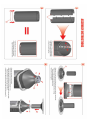
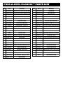
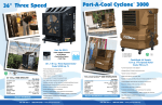
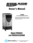
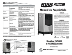
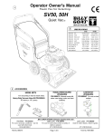
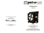
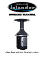
OWNERS MANUAL
Please Read and Save These Instructions
UNIT OVERVIEW
SAFE OPERATION
To reduce the risk of electric shock, fire or injury:
• Do not operate any unit with a damaged cord or plug. Discard unit or return to an authorized
service facility for examination and/or repair.
• Do not run cord under carpeting. Do not cover cord with throw rugs, runners, or similar coverings.
Arrange cord away from traffic area where it will not be tripped over.
• Read instructions and labels carefully.
• Always unplug the electric cord to the Port-A-Cool unit before performing inspections or repairs.
• Plug into three-prong grounded GFCI protected electrical receptacle only.
• Do not operate if there is any damage to the plug or cord.
• Do not step on or roll over power cord with heavy or sharp objects.
• Do not operate unit unless all pads are securely in place.
• Remove the plug from the electrical receptacle by pulling on the plug and not the cord.
• Test the GFCI receptacle or breaker monthly to ensure it is functioning properly.
• Do not operate near open containers of flammable liquids or gases.
• Never wash the unit cabinet with a garden hose; water may harm the motor and electrical system.
• If the unit is damaged or it malfunctions, do not continue to operate it. Refer to the warranty,
troubleshooting or FAQ section, call Port-A-Cool, LLC, Technical Support at 1-888-266-5243, or email
[email protected].
SETUP
Unpacking the PORT-A-COOL Islander™ unit.
TOOLS REQUIRED: HEX KEY (ALLEN WRENCH) that is provided in the product packaging
PORT-A-COOL Islander™ units are shipped partially assembled in three pieces. Cut the straps and remove
Box 1 from the base of the unit by lifting it up. Remove the protective plastic dust cover and lift the unit off
the pallet. Cut the straps from Box 2, containing the air stack. Remove the packing material and lift from box.
Cut the strap from Box 3 and remove the top from the packaging material. Place the top on top of the air stack
and secure using including screws. Fit the assembled pieces on top of the base and secure using included
screws.
Connecting the water and electricity.
Water Connection
PORT-A-COOL Islander™ unit must be in upright and level position
Locate the brass hose adapter on the side of the unit near the water adjustment and drain valves. Verify
that the hose washer is in position and in good condition. Attach a standard garden hose to the brass hose
adapter and tighten to preclude leaks. Turn water on to fill the sump tank.
The PORT-A-COOL Islander™ model also includes a manual fill option. To fill the tank manually, slide out
the drawer located next to the hose adapter mentioned above and fill with water. Close the drawer and the
unit is ready for operation.
Visually inspect water connections for leaks and verify that the connections are secure. Remove the pads
by following the instructions in this owners manual. Once the sump tank is filled, the water flow should cease
and the inlet connections may now be visually checked for leaks. All of these inspections have been performed at the factory but shipping may have caused connections to loosen. Replace the pads by reversing the
removal operation.
Electrical Connection
PORT-A-COOL Islander™ unit must be in upright position with cooling pads
installed!
This model utilizes a single power cord and control panel. Before connecting the plug to an outlet, ensure that
there is no standing water where the cord may lie or the operator is standing. The use of separate multiple outlet
devices are not recommended.
When making electrical connections, ensure that local and national codes are adhered to. Use only with
GFCI Protected Receptacles. Please refer to the Barcode Product Label on the side of the unit for specific electrical requirements.
OPERATING PROCEDURES
Specifications
The PORT-A-COOL Islander™ cooling unit includes the following specifications:
Speeds
Air Delivery CFM
Total Amps
Water reservoir
Dimensions
Unit weight
Shipping weight
Box Size
Cooling Capacity
Variable
2,500
10.8
20 gallons
88” h x 38” w x 38” d
165 lbs.
225 lbs.
65” h x 40” w x 34” d
360˚ radius airflow
Please ask for additional specifications, if required, from your distributor, check the serial number plate, or
visit www.port-a-cool.com for the specifications for your Port-A-Cool Islander™ unit.
Placement of the PORT-A-COOL Islander™ unit.
There are three primary considerations when deciding where to place the PORT-A-COOL Islander™ unit.
A primary consideration is the direction of the airflow. The PORT-A-COOL Islander™ unit creates a fanshaped air pattern that concentrates cool air flow in a vertical pattern from the multiple louvers located in the
bonnet. This pattern may be disturbed or broken up by obstacles such as shelves, work benches, etc. It is
important to ensure that a clean, unbroken path for the air from the unit is provided to the maximum extent
possible.
The unit must be level and in the upright position. When supporting with a platform, allow for the full
weight of a functioning unit by including the weight of the water, both in the sump tank and the added weight
of the water saturated cooling pads. The total weight could be in excess of 500 lbs. (227 kg.).
When the PORT-A-COOL Islander™ unit is placed near a wall or other obstruction, it is recommended that
a distance of at least 3 feet (1 meter) from the wall or obstruction to the face of the cooling pads be maintained. This allows the unrestricted flow of warm air to the cooling pad side of the unit. When using multiple
units in close proximity, be sure to aim the unit so that the air flows complement each other and not oppose.
Opposition will negate the airflow and allow an area of dead air to accumulate between units.
Starting the pump and adjusting the water flow
Once the water tank is full, setting the pump to “ON” will turn on the pump. When initially turning on the
pump, the level in the tank will drop suddenly and restart the flow of supply water. This is a normal condition, as the cooling pads require a large amount of water for proper wetting. When the PORT-A-COOL
Islander™ unit is first operated, the new pads will require an initial ‘breaking-in’ period. This period is
required for the pads to begin readily absorbing water. It may require up to a week to achieve maximum
efficiency.
It is important to ensure that the spray bar is properly adjusted when first starting the water flow in the
PORT-A-COOL Islander™ unit. Increasing the flow using the SPRAY BAR ADJUSTMENT valve on the side of
the unit makes this adjustment. Proper water adjustment should leave the pads saturated with water, but
not flooded. Pads should appear wet, however, cascading amounts of water can actually reduce cooling
efficiency. Proper adjustment will prevent problems and increase cooling capacity. When turning the unit off
at the end of the day or week, the pump should be turned off about 15 minutes before the unit to allow the
cooling pads to dry. This will increase the life of the pads.
Starting the unit
(Cooling pads must be installed)
Start the fan by turning the fan switch to the ‘ON’ position, or to one of the available speeds on the multispeed models. On the multi-speed model, it is preferred to step slowly through the speeds allowing the
fan to obtain its full speed at the LOW speed before going to MEDIUM and before going to HIGH.
MAINTENANCE & STORAGE
Very little maintenance is required on the PORT-A-COOL Islander™ unit. Cleanliness is the most important
part of a maintenance program. Keeping the unit clean will do more than any other single item to keep your
unit in peak operating condition. The rugged, corrosion-resistant construction of the unit and industrial grade
components ensure low maintenance characteristics. In excessively dusty or dirty environments, optional filters are available from your distributor or at www.port-a-coolparts.com
Daily Maintenance
Daily maintenance is an operational routine rather than actual maintenance. On a daily basis, the pump
should be turned off approximately 15 minutes before the fan is turned off. This will allow the cooling pads
to dry out and extend their life. This also helps to control the growth of mildew, mold, bacteria and other
odor causing elements.
Weekly Maintenance
At the end of the week or at a scheduled time, the unit should be shut down and the sump tank should
be drained. Closing the Spray Bar Adjustment Valve and opening the Drain Valve will accomplish this. If
desired, a hose may be attached to the Drain Valve to direct the drained water to a remote disposal area.
Once the Drain Valve is open, starting the pump will drain the unit. When the pump has removed most of
the water, a small amount will be left in some areas. Removal of the drain plug will accomplish the same
results without the use of the pump.
Once the sump is drained and the power disconnected, the pads may be removed to allow inspection
and cleaning of the sump tank. Dust may collect in the sump tank over time. This dirt, and any remaining
water, may be vacuumed out using a wet/dry shop vacuum and wiped clean with a cloth. Also, inspect and
clean the Inlet Strainer located on the bottom of the pump. Replace pads in correct airflow direction, referring to the label on the pads.
Storage
1) Drain all water from the sump tank and clean, ensuring that the pads and sump are completely dry.
2) Roll up the electrical power cord and secure it to ensure that it will not be rolled over, tripped over, or
caught in equipment.
3) Cover the unit completely to prevent dust build-up and store in a dry area. This also helps to prevent damage
to the pads. Optional dust covers are available from your distributor or at www.port-a-coolparts.com.
TECHNICAL SUPPORT
Technical support and service is available directly from your distributor or call PORT-A-COOL, LLC
Technical Support Hot Line at 888-266-5243 for the distributor nearest you. You may also contact the Support
Hot Line for consultation on troubleshooting and parts replacement.
Please have serial number and model number of unit available.
WARRANTY AND REPLACEMENT PARTS
Port-A-Cool® Unit Limited Warranty
For one year from date of installation, PORT-A-COOL, LLC warrants any original component part or parts
of the PORT-A-COOL® evaporative unit found, upon examination by factory-authorized personnel, to be
defective in material or workmanship, excepting, however, that the high-performance, fan motor utilized as a
component of the Port-A-Cool® HP portable evaporative cooling unit shall be warrantied by PORT-A-COOL,
LLC for a period of three years from the date of installation. All transportation charges on parts submitted for
replacement or repair under this warranty must be borne by the purchaser. If said equipment develops such
defects within this period, it will be repaired or replaced at our option. For breach of any implied or written
warranty on this product, PORT-A-COOL, LLC., shall not be liable for any incidental or consequential damages.
This warranty is declared void if the equipment is found to have been misused, abused or tampered with by
unauthorized personnel.
Due to warranty limits placed on our products by the original manufacturers, our warranty is limited on
manufactured units and their original component parts as well as replacement parts to a total of one (1) year
after the date of installation, with the above noted 3-year warranty relating to the high-performance fan motor
utilized as a component of the PORT-A-COOL® HP portable evaporative cooling unit being the only exception.
Returned Merchandise Authorization (RMA) Procedures
All Port-A-Cool® units, parts, or materials being returned to PORT-A-COOL, LLC for warranty replacement or
repair require an RMA (Return Merchandise Authorization) number.
Warranty parts can be replaced by:
The distributor can purchase the part with an RMA number and will only be charged for
1.
the cost of the part, not for the shipping. When the defective part is returned freight paid, the
distributor’s account will be credited for the cost of the part.
2.
The customer / distributor can call Tech Support to get an RMA number to send the
defective part back to PORT-A-COOL, LLC. Once the part is received by PORT-A-COOL, LLC, a
replacement part will be sent at no charge.
Information needed to get an RMA number:
1.
The unit serial number.
2.
The unit model number (ex. PAC2K363S)
The part number or description of the part to be replaced.
3.
Only major component parts need an RMA number, i.e. fans, motors, pumps, and some plumbing parts.
For replacement of small parts, the serial and model numbers are still required, but the parts do not need to
be returned to PORT-A-COOL, LLC.
For warranty replacement parts call PORT-A-COOL® Technical Support at 1-888-266-5243. FAX: 936-598-1431.
Shipping Address
Mailing Address:
PORT-A-COOL, LLC
PORT-A-COOL, LLC
721 FM 2468
P.O. Box 2167
Center, Texas 75935
Center, Texas 75935
FREQUENTLY ASKED QUESTIONS
Q. WHAT IS THE BEST ENVIRONMENT FOR THE PORT-A-COOL ISLANDER™
UNIT TO PRODUCE THE MOST COOL AIR?
A. For optimum performance, the temperature should be 85 degrees F or higher
and the relative humidity should be below 75%. However, PORT-A-COOL
ISLANDER™ units will reduce the temperature in almost any environment, making
it more pleasant.
Q. WHAT IS THE DIFFERENCE BETWEEN EVAPORATIVE COOLING AND
MISTING SYSTEMS?
A. Misting units spray a shower of water into the air that will collect on people,
objects, equipment, floors, etc. The PORT-A-COOL ISLANDER™ unit uses the process of evaporation to produce cooler air, but does not discharge a mist.
Q. IS AN OUTSIDE AIR SOURCE REQUIRED FOR EVAPORATIVE COOLING?
A. Yes. The introduction of outside air is what keeps the air fresh and optimizes
the evaporative cooling process. The PORT-A-COOL ISLANDER™ is great for outdoor use, but can also be used in open interior areas by placing the unit next to a
door or window that’s slightly open.
Q. WHERE CAN I BUY REPLACEMENT PARTS?
A. Unit replacement parts may be purchased from any PORT-A-COOL® product
distributor or directly from Port-A-Cool® Parts/Technical Support department. You
may also visit www.port-a-coolparts.com to order online.
Q. HOW OFTEN DO PADS HAVE TO BE REPLACED?
A. Depending on the quality of maintenance and frequency of use, pads typically
last up to five years. However, should you have any questions about the life of
the pads for your unit, please call our tech support department for more detailed
information about replacing your pads.
PORT-A-COOL Islander™ UNIT OVERVIEW
Adjustable
Louvers
Tilt and Roll
Handle
Air Stack
Control
Panel
Cord
Wrap
Cooling Media
Quick Access Cover
Water Adjustment
Valve
PORT-A-COOL Islander™ USER INTERFACE
The user interface includes touch sensitive buttons for operation of the
Hurricane 3600. The user interface also includes status indicator LEDs and a
7-segment LED display to show the cooling unit’s status.
1
Power
The green Power LED is illuminated when the unit is plugged in.
7
2
6
3
5
Water level
The red water level LED is illuminated when the float switch detects
a low water level and the pump is not being allowed to turn on. This
LED flashes if the pump is running during a low water occurrence to indicate
that more water needs to be added in order to continue running the pump.
1
2
3
Timer
The controller features five pre-programmed modes which control
the fan / pump sequence for a pre-defined period. Each touch of
the program button cycles through the five modes: 1HR, 2HR, 4HR, 8HR, and
TIMER OFF. During the program run, the user can adjust the maximum fan speed with
the up and down buttons. When the program is active, the Timer LED will be on and,
for five seconds, the user will be shown which program (1H, 2H, 4H, or 8H) is active.
LED is illuminated when the Timer button is activated in 1, 2, 4, or 8-hour modes. The
LED flashes slowly if continuously held and flashes quickly if the timer is enabled and
then the Pump or Fan buttons are continuously held, prompting the user to turn off the
timer in order to exit fan and pump operation.
Slider
The touch slider controls the speed setting of the fan. If the slider is
touched on the “+” end of the slider spectrum, then the fan speed requested is the
maximum, 100% (“HI”). If the slider is touched on the “–” end of the slider spectrum,
then the fan speed requested is the minimum, 33% (“LO”). A touch anywhere between
the “+” and “–” of the slider adjusts the fan speed in 1% increments.
Two digits display the unit’s temperature, fan speed, and timer program. If the unit
does not have a temperature sensor connected, the display will constantly show fan
speed. If the unit does feature a temperature sensor, then the temperature is displayed
unless: a fan speed change is being called upon either by means of a slider touch or
by the timer’s program. When a fan speed change is requested, the fan speed will be
displayed for 5 seconds before returning to the unit temperature.
4
5
Pump
Press the pump button once to power on and again to power off. The
green Pump LED is illuminated when the pump is enabled. The LED flashes
slowly if continuously held and the timer is disabled.
6
Fan
When the fan is off, touch the Fan button once to turn the fan on in full
speed. When the fan is on, touch of the Fan button again to turn the fan
off. The green Fan LED is illuminated when the Fan is active. The LED
flashes slowly if continuously held and the timer is disabled.
7
7-Segment LED Display
LEDs are used to display the status of the cooling unit. The green Timer
4
Pre-programmed timer function
1) Pump starts (includes five second delay to Allow water to start
reaching the pads)
2) Fan starts at 100% (hi) speed (a “kick start” for Best variable speed
motor operation)
3) Fan ramps down to 50% speed
4) Fan ramps up to full speed in 10% steps at 1 Minute intervals
(begin increasing airflow as The pads wet out for best efficency)
5) Fan runs at maximum speed for the duration of The timer setting
(100% speed is default, or it Can be whatever the user selects)
6) Pump shuts off when timer setting expires
7) Fan ramps down to 50% speed
8) Fan runs 30 minutes (pad drying period)
9) Fan shuts off
UNIT OPERATION WARNINGS
1) Not intended for use by children
2) Not intended for use by persons with reduced physical, sensory or
mental capabilities
3) Not intended for use by persons with lack of experience and
knowledge, unless they have been given instruction and are
supervised during operation
4) Children should be supervised to ensure that they do not play
with the appliance
PORT-A-COOL Islander™ WIRING DIA-
PORT-A-COOL Islander™ EXPLODED VIEW
43
18
29
27
27
28
2
45
30
15
38
31
4
7
10
4
9
8
14
38
44
26
44
23
24
19
12
42
25
46
41
16
12
36
46
46
47
35
3
12
37
34
41
33
24
13
19
23
17
3
33
39
22
42
32
40
6
11
11
21
5
20
1
PORT-A-COOL Islander™ PARTS LIST
ITEM#
ITEM#
PART #
DESCRIPTION
1
ACCDOOR-PAT-208 WATER FILL DOOR - BACK ACCESS PANEL MTNG
PART #
DESCRIPTION
25
HOSE-FTG-04
T BARB ADAPTER
2
AIRDUCT-PAT-202
AIR DUCT OUTLET LOUVER MOUNTING SECTION
26
INNFRA-PAT-5120
INNER FRAME WELD
3
AIRFOIL-PAT-613
AIRFOIL FOR PATIO UNIT
27
LOUVERS-PAT-507
LOUVERS FOR PATIO UNIT (6)
4
AIRSTACK-PAT-204
AIRSTACK 19” PATIO UNIT (2) PER UNIT
28
MOTOR-MNT-ARM
CYCLONE UNIT TRI-ARM MOTOR MOUNT
5
BACKPNL-PAT-207 BACK ACCESS PANEL - CONTROL MTNG SECTION
29
MOTOR-MNT-BND-2
CYCLONE QUAD-MOTOR BELLY BAND
CASTER BASE ASSEMBLY
30
MOTOR-010-07
PATIO UNIT VARIBLE SPEED MOTOR
BLOWER-WHL-01
CYCLONE 3000 BLOWER WHEEL
31
ORING-271-70
271 BUNA N 70 O-RING - 9.25 x 9.5 x .139
BLOWER-01
BLOWER HOUSING - CYCLONE 3000
32
PAC-PLB-14
1/4”X3/4” GHT BRASS FITTING HOSE ADAPTER
CAPACITOR-05
40uF CAPACITOR FOR MOTOR
33
PAD6019/G
6” X 12” X 19” 55/20 ANGLE KUUL PAD (2)
10
CAP-BOOT-01
THERMAL INSULATOR FOR CAPACITOR
34
PAT-TANK-01
20 GALLON PATIO UNIT TANK
11
CASTERS-RDG-4
RIDGED POLYFIN CASTER
35
POWERCORD-01
16’ POWERCORD WITH STRAIN RELIEF
12
CLAMP-01
WIRE TUBE CLAMP
36
PUMP-BRACKET-5
PUMP MOUNT BRACKET FOR CYCLONE UNIT
13
CTRL-VS-11
90-250V 10/6 AMP ELECT. TOUCH PAD CONTROL
37
PUMP-CYC-3
CYCLONE PUMP - OK400
14
COLHAN-PAT-614
COLUMN HANDLE
38
S-1420-25BH
1/4-20X2.5 BUTTON HEAD SCREW SOCKET CAP
6
BASE-PAT-616
7
8
9
15
COLSUP-PAT-5121
COLOMN SUPPORT WELD
39
SENSOR-TEMP-11
10koHM TEMPERATURE SENSOR KIT
16
CORDMGT-PAT-206
POWERCORD PANEL-CORD MANAGEMENT
40
SPIN-FTG-01
SPIN FITTING FOR DRAIN
17
DRAIN-PLUG-01
NPT PLUG FOR DRAIN
41
SPRAY-ACC-04
HAYCO CLAMP FASTENER
18
DUCTTOP-PAT-203
AIR DUCT TOP INTERNAL DIVERTER SECTION
42
SPRAY-PAT-01
SPRAY BAR FOR PATIO UNIT
19
FLAP-PAT-1
PAD FLAP FOR PATIO UNIT
43
TOP-PAT-211
TOP PIECE FOR PATIO UNIT
20
FLOATSWITCH-11
LOW WATER SENSOR SWITCH
44
TRANS-PAT-205
TRANSITION PIECE - BASE TO STACK (2) PIECES
21
FLOAT-ACC-18
FLOAT SUPPORT BRACKET
45
TUBETR-PAT-5122
TUBING TRANSITION PIECE
22
FLOAT-CYC-03
FLOAT VALVE FOR FOR CYCLONE UNIT
46
TUBE-01
SOFT PLASTIC TUBE
23
GRILL-PAT-209
PAD COVER GRILL - PAD ACCESS COVER
47
VALVE-01
FLOW CONTROL GATE VALVE
24
HANDLE-PAT-210
MID UNIT HANDLE
®
Portable Cooling Solutions
Unit 2 – 26 Lancaster Rd Wangrara
PO Box 1994 Wangara WA 6065.
www.portacoolaustralia.com.au
[P] 08 9408 0801 [F] 08 9408 08025
PAC-ACC-09