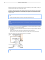
1
Deploying
Ekahau RTLS with
Ekahau Site Survey
Ekahau, the Ekahau logo, Ekahau Site Survey, Ekahau Location Survey, Ekahau Engine, Ekahau
Positioning Engine, Ekahau Manager, Ekahau Activator, Ekahau Finder, Ekahau Tracker, Ekahau
Logger, Ekahau T201, Ekahau T301, Ekahau NIC-54, Ekahau NIC-300, Ekahau Client, and Ekahau
Positioning Client are trademarks or registered trademarks of Ekahau.
Other product and company names may be trademarks or trade names of their respective owners.
The enclosed software contains implementations of Ekahau’s patent pending inventions.
This manual and the Ekahau software described in it are copyrighted, with all rights reserved. This
manual and the Ekahau software described in it may not be copied, except as otherwise provided
in your software license.
The contents of this document are provided “as is.” Except as may be required by applicable law,
no warranties of any kind, either express or implied, including, but not limited to, the implied warranties of merchantability and fitness for a particular purpose, are made in relation to the accuracy,
reliability or contents of this document. Ekahau reserves the right to revise this document or withdraw
it at any time without prior notice.
Export of this technology may be controlled by the United States Government. Diversion contrary
to U.S. law prohibited.
Your use of the Ekahau software described in this user manual and its documentation are governed
by the terms set forth in your license agreement. Your use of this Ekahau software contrary to the
terms of this User Manual may void the warranty, if any, described in your license agreement.
Under no circumstances shall Ekahau be responsible for any loss of data or income, or any special,
incidental, punitive, consequential or indirect damages howsoever caused.
You may not use any Ekahau software or hardware products in hazardous environments (such
as operation of nuclear facilities, aircraft navigation or control, environments containing high levels
of dust, or mines) or in Life-Critical Solutions, unless you have advised Ekahau that they will be
used in a hazardous environment or in a Life-Critical Solution and Ekahau has had an opportunity
to evaluate further whether, and on what terms and conditions, the software or hardware products
may be licensed for your intended use. The term “Life-Critical Solution” means an application
software package or hardware device whose functioning or malfunctioning may result directly or
indirectly in physical injury or loss of human life.
Ekahau tags must always be used in compliance with the user environment and instructions contained in the User Manual for the tags.
Copyright © Ekahau, Inc. 2000-2008. All rights reserved.
Ekahau Site Survey User Guide for Deploying Ekahau RTLS
iii
Table of Contents
1 Introduction ....................................................................................................................... 1
1.1 Ekahau RTLS ........................................................................................................... 1
1.2 Ekahau Site Survey ................................................................................................. 3
1.2.1 Overview ...................................................................................................... 3
1.2.2 Features ....................................................................................................... 3
1.3 Technical Support .................................................................................................... 4
1.4 Backward Compatibility ............................................................................................ 4
1.4.1 Ekahau Site Survey 2.2 - [.ess] ................................................................... 4
1.4.2 Ekahau Positioning Engine / Ekahau Manager 3.1 - [.edb] ......................... 5
1.4.3 Ekahau RTLS 4.x - [.esx] ............................................................................. 5
2 Installation ......................................................................................................................... 7
2.1 System Requirements and Software Limitations ..................................................... 7
2.1.1 Supported Wi-Fi Adapters ........................................................................... 7
2.2 How to Install ........................................................................................................... 9
2.2.1 Wi-Fi Network Adapter Driver Update ......................................................... 9
2.2.2 Upgrading the Ekahau Site Survey License .............................................. 10
3 User Interface Overview ................................................................................................ 13
3.1 Map View ............................................................................................................... 13
3.2 Visualization Selections ......................................................................................... 14
3.3 Toolbar ................................................................................................................... 14
3.4 Survey and RTLS Tools ......................................................................................... 14
3.5 Menus .................................................................................................................... 16
3.6 Toolbar ................................................................................................................... 18
3.7 The Access Point List ............................................................................................ 19
3.7.1 Selecting Access Points ............................................................................ 19
3.7.2 Searching for Access Points ...................................................................... 20
3.7.3 Limiting the Access Points to Visualize ..................................................... 20
3.7.4 Selecting My Access Points ....................................................................... 21
3.7.5 Renaming Access Points ........................................................................... 21
3.7.6 One AP, several MAC addresses: Joining APs ......................................... 21
3.8 Survey List ............................................................................................................. 22
3.9 Zone List ................................................................................................................ 22
4 Creating a Project ........................................................................................................... 23
4.1 Setting the Map and Scale ..................................................................................... 23
4.1.1 Changing the Map Image .......................................................................... 25
4.1.2 Changing the Map Type in Outdoor or Mining Environments .................... 25
4.1.3 Grouping Maps into Buildings in Multi-Building Environments .................. 25
4.2 Creating Rails ........................................................................................................ 26
4.3 Creating Open Spaces ........................................................................................... 29
4.4 Performing Surveys ............................................................................................... 29
4.4.1 Moving and Deleting Survey Points ........................................................... 31
4.4.2 Placing Access Points on the Map ............................................................ 31
4.4.3 Configuring the Wi-Fi device ...................................................................... 32
4.4.4 Surveying with Ekahau T301-A Location Tag ............................................ 33
4.4.4.1 Surveying with Tags Operating in Blink Mode ............................ 34
4.4.5 Surveying with Ekahau T201 Location Tag ................................................ 36
4.4.6 Merging Two Projects as One .................................................................... 38
4.5 Defining Zones ....................................................................................................... 38
4.6 Improving Room Accuracy with Location Beacons ................................................ 39
Ekahau Site Survey User Guide for Deploying Ekahau RTLS
iv
4.7 Communicating with Ekahau Positioning Engine ................................................... 40
5 Analyzing Location Tracking Accuracy ....................................................................... 41
5.1 Accuracy Variables ................................................................................................. 41
5.2 Accuracy Statistics ................................................................................................. 42
5.3 Real-Time Testing of Accuracy .............................................................................. 42
5.4 Location Quality Filter ............................................................................................ 43
5.5 Analyzing and Troubleshooting Accuracy .............................................................. 44
5.5.1 In-depth Accuracy Analysis Using Error Vectors ....................................... 45
5.5.2 Analyzing Survey Measurements .............................................................. 46
5.6 Visualizing Accuracy and RF Signals .................................................................... 47
5.6.1 Accuracy - How Accurate is the RTLS? ..................................................... 48
5.6.2 Calibration Quality - Have Enough Surveys Been Performed? ................. 49
5.6.2.1 Rail Width - How is the Surveyed Data Used on the Rail? ......... 50
5.6.3 Zone Similarity - Can the RTLS Identify the Zones? ................................. 51
5.6.4 Number of Access Points - How Much Signal Overlap is there? ............... 53
5.6.5 Strongest Access Point - With which AP does the Client Associate? ....... 53
5.6.6 Signal Strength - How is the Signal Coverage? ......................................... 54
5.6.7 Location Coverage - Is the Network Sufficient for RTLS? ......................... 55
5.6.8 Location Quality ......................................................................................... 56
5.6.9 Visualization Options and Refreshing ........................................................ 57
5.6.9.1 Visualization Modes .................................................................... 57
5.6.9.2 Signal History .............................................................................. 58
5.6.9.3 Refreshing the Visualization ....................................................... 59
6 Maintaining the Project .................................................................................................. 61
6.1 Replacing Access Points ....................................................................................... 61
6.1.1 Replacing Single-MAC and Multi-MAC Access Points .............................. 61
7 Reporting, Exporting and Printing ................................................................................ 63
7.1 Generating Reports ................................................................................................ 63
7.2 Exporting and Printing Images ............................................................................... 65
Index ..................................................................................................................................... 67
Chapter 1. Introduction
1
1 Introduction
Welcome to Ekahau Site Survey (ESS), a tool for calibrating Ekahau Real-Time Location System
and verifying its accuracy. This user guide helps you to understand how to use Ekahau Site Survey
for deploying Ekahau Real-Time Location System, and how it is related to the other components
of Ekahau RTLS. Ekahau Site Survey is also used for designing, deploying and managing Wi-Fi
networks, however this user guide focuses on deploying and Real-Time Location Systems. See
Ekahau Site Survey User Guide to learn more about Wi-Fi design, deployment and management
using Ekahau Site Survey.
Note
Do not operate Ekahau Site Survey and drive or carelessly walk at the same time. Stop using
ESS and switch off the Wi-Fi device when it is forbidden to use radio equipment or when it may
cause interference or danger.
Tip
If some of the functionality described in this document is not available in the user interface,
ensure that RTLS Features are enabled in File > Preferences.
1.1 Ekahau RTLS
Award Winning Concept
The wireless networks that are used for data and voice today provide an excellent platform for
building accurate location-tracking systems. Unlike other proprietary systems, Ekahau’s system
relies on standard 802.11 wireless networks to deliver a comprehensive real-time location system
(RTLS) for locating your valuable equipment and people in real time. Because the existing wireless
network infrastructure is used, deployment is more cost effective where a wireless network is
already in use. This provides additional justification for installing new networks. Deployment of
Ekahau RTLS does not interrupt network activities or affect other network communications.
With Ekahau RTLS, the positions of equipment and people are automatically updated and can be
delivered to other systems and personnel that call for this information. The fact that information
about the needed equipment or persons is readily available leads to cost savings, because the
assets are utilized more efficiently and the workflow is optimized. Moreover, the system enables
new processes, such as the automatic routing of security personnel to the location where a tag
alarm button was pressed or a tamper switch was activated.
Chapter 1. Introduction
2
Product Components
Ekahau RTLS is a whole tracking solution for asset and people tracking. It consists of the following
integrated components
Component
Description
Supported Platforms
Ekahau Positioning Engine™
Server software for location tracking, Windows® XP, Windows® 2003
Wi-Fi tag configuration and manage- Server
ment. HTTP / XML API for applications.
Ekahau Site Survey™
Application for creating and editing Windows® XP, Windows® 2000
positioning models.
Ekahau Vision™
End-user application for grouping, Windows® XP, Windows® 2003
locating and viewing the location of Server
people and assets in real time,
monitor events, and invoke notifications or alarms.
Ekahau Wi-Fi Tags
Wi-Fi location tag
-
Chapter 1. Introduction
3
Component
Description
Supported Platforms
Ekahau Client
Software based solution to provide
location tracking, capabilities for WiFi enabled devices. Reference
implementation and Ekahau Tag
Protocol documents available to
Located by Ekahau™ partners.
Windows® Vista, Windows® XP,
Windows® 2000, Windows® Mobile
6, Windows® Mobile 2005, Windows® Pocket PC 2003, Windows®
CE 4.2, Windows® CE 5.0
What Is RTLS?
A Real-Time Location System (RTLS) is a fully automated system that continually monitors the
location of assets or personnel in real time. An RTLS provides real-time information to authorized
users via a corporate network through application software or application programming interfaces.
Typically, an RTLS consists of tags, a wireless data network, server software and end-user
application software. Ekahau RTLS uses signal strength measurements from existing Wi-Fi (802.11
a/b/g) access points for location tracking, which lowers the total cost of ownership and makes
deployment straightforward compared to other RTLS solutions that require proprietary wireless
infrastructure.
1.2 Ekahau Site Survey
1.2.1 Overview
Ekahau Site Survey is a tool for creating a Positioning Model to enable accurate location tracking.
In addition, it is used for analyzing the wireless network and location tracking accuracy. Using
ESS, you can also track a local Wi-Fi device, such as a laptop or a Wi-Fi tag.
In terms of wireless LAN signal behaviour, every site is unique. In Ekahau RTLS, Ekahau Positioning
Engine must be aware of these signal and site characteristics to accurately locate Wi-Fi devices.
Ekahau Site Survey is used to record signal measurements, define the environment and communicate them to Ekahau Positioning Engine. In Ekahau Site Survey, you create what is called a
Project, which includes all the surveyed signal data, as well as the information about the environment, such as Tracking Rails. When a Project is saved, it becomes a Positioning Model.
Ekahau Site Survey is a software-only tool that typically runs on a laptop computer. Ekahau Site
Survey replaces what was previously called Ekahau Location Survey, and before that, Ekahau
Manager.
1.2.2 Features
The main features of ESS are:
●
●
●
●
●
●
●
Opening Ekahau Manager and ESS files
Recording signal measurements by performing a survey
Defining the Environment (Open Spaces and Rails) and Zones
Analyzing and optimizing location accuracy
Saving the Project to Ekahau Positioning Engine
Tracking the local Wi-Fi device (Wi-Fi tag or Wi-Fi Network Adapter)
Merging several Projects as one file (support for multiple simultaneous surveyors)
Chapter 1. Introduction
●
4
Full site survey and network planning capabilities, see Ekahau Site Survey User Guide for
details
With its support for large maps and multiple floors, ESS is suitable for large-scale deployments.
Note
Some of the features of Ekahau Site Survey are available in Ekahau Site Survey Professional
version only. However, these features do not concern RTLS deployment. Please see Ekahau
Site Survey User Guide for details.
1.3 Technical Support
Ekahau provides technical support free of charge for all customers for 30 days. Customers who
have purchased Ekahau Support will receive Ekahau Support services for 12 months from the
date of purchase.
Ekahau Support includes:
●
●
All upgrades and patches for the product(s) and documentation purchased
Free-of-charge support via e-mail (preferred) and telephone during regular business hours
(PST, EST, GMT+2)
Bug fix patches are free of charge for all customers.
To renew your Ekahau Support, please contact your Ekahau representative or [email protected].
1.4 Backward Compatibility
Ekahau Site Survey is backwards compatible with the following Ekahau products:
1.4.1 Ekahau Site Survey 2.2 - [.ess]
In ESS, you can use Ekahau Site Survey 2.2 survey data for calibrating the Positioning Model.
However, in many cases the existing site survey may not provide optimal location accuracy: In
some cases the site survey data does not cover the whole location tracking area. It is also always
recommended to calibrate the Positioning Model using the Wi-Fi device that will be used in the
location tracking.
Ekahau Site Survey 2.2 Projects do not include Rails, Open Spaces or Zones. In order to use
Ekahau Site Survey 2.2 Projects with RTLS 4, open them in ESS first, and then save them to
Ekahau Positioning Engine after making the necessary adjustments.
The surveys perfomed with Ekahau Site Survey 2.2 are selected as Calibration Surveys bv default
in ESS.
Chapter 1. Introduction
5
1.4.2 Ekahau Positioning Engine / Ekahau Manager 3.1 - [.edb]
Ekahau Positioning Engine 3.1 calibration data has been collected at certain points (sample points)
instead of conducting constant surveys. When importing, each Ekahau Positioning Engine sample
point will be converted into a single survey. Ekahau Positioning Engine Positioning Models do not
include Open Spaces. You can add Open Spaces to Ekahau Positioning Engine 3.1 Models using
ESS. The Logical Areas in 3.1 Models are automatically converted into Zones.
Positioning Models were previously created with Ekahau Manager. Ekahau Site Survey fully
replaces Ekahau Manager. A few differences ramain:
●
Whereas Ekahau Manager used sample points as the calibration data, Ekahau Site Survey
uses continously recorded survey data.
●
Open areas, where no known paths of movement can be defined, were defined with a "grid
of Rails" in Ekahau Manager. In Ekahau Site Survey, these are replaced by Open Spaces.
In Ekahau Manager, Engine was needed for the Merge feature. In Ekahau Site Survey, no
Engine is needed.
●
The Ekahau Manager calibration Sample Points are imported as Calibration Surveys and the
Accuracy Analysis test cases are imported as Test Surveys by default in ESS.
Note
The access points that have been disabled from location tracking in Ekahau Manager will not
be imported into Ekahau Site Survey.
1.4.3 Ekahau RTLS 4.x - [.esx]
When updating from the previous 4.x versions, the following will apply:
●
●
●
●
Ekahau Positioning Engine v4.0/4.1 and Ekahau Location Survey v4.0/4.1 Projects are different
from Ekahau Site Survey 4.4 Projects
The latest version of Ekahau Positioning Engine is compatible with Projects from previous
4.x versions (.esx files), however Projects created with the latest version of Ekahau Site Survey
do offer optimized performance and consume less memory
Ekahau Site Survey 4.4 is compatible with previous Ekahau Location Survey 4.x Projects
(.esx files)
Ekahau Site Survey 4.4 always handles and saves the Projects in Ekahau Site Survey 4.4
format, regardless of the file format version of the opened Project
As a general rule, update both Ekahau Site Survey and Ekahau Positioning Engine at the
same time to avoid incompatibility issues. When updating to the latest Ekahau Positioning
Engine from versions Ekahau Positioning Engine 4.0 or 4.1, it is recommended to perform the
following actions to the Positioning Model:
1.
2.
3.
4.
Open your "old" Project in Ekahau Site Survey 4.4
Select Site > Auto-Detect Multi-MAC Access Points
Select Automatic Binding of Access Points, and ensure all the AP brands in use will be checked
(it is OK to have them all checked). Click OK.
Select Site > Automatically Place Access Points to allow Ekahau Site Survey to find the
AP locations. Verify that the access points are placed to their true locations.. Move APs to
Chapter 1. Introduction
5.
their proper locations if the positions estimated by Ekahau Site Survey are significantly
incorrect.
Save the Project to Ekahau Positioning Engine, and activate it.
The advantage of performing the previous actions is that the Project is now in the latest format,
which delivers improved performance with the latest Ekahau Positioning Engine.
6
Chapter 2. Installation
7
2 Installation
2.1 System Requirements and Software Limitations
The following hardware and operating system are required to run the program:
●
●
●
●
●
●
Windows XP, 2000 or Vista Operating System
1GB RAM (2GB or more recommended for Projects larger than 300,000 square feet)
1GB free hard disk space
A supported Wi-Fi device, see below
Laptop computer (required for recording surveys, a desktop computer is sufficient planning
and analysis)
Screen resolution of 1024 x 768 or higher, 32-bit color quality recommended
Please consider the following limitations that apply to the program:
●
●
●
The software may become unstable if a single Project file contains more than 5000 access
point MAC addresses
The software may become unstable if images larger than 5000 x 5000 pixels are used (a
maximum image size of 2500 x 2500 is recommended)
The software may become unstable if more than 50 hours of survey data is recorded into a
single Project
Warning
Windows Vista cannot be used for Calibration with a Wi-Fi tag, or with Ekahau Activator. Thus,
do not use a Windows Vista-based laptop for deploying RTLS.
2.1.1 Supported Wi-Fi Adapters
Ekahau Site Survey supports most common 802.11 Wi-Fi network adapters for conducting surveys.
A wireless network adapter is not required if you do not wish to record signal data.
The following external ExpressCard and Cardbus adapers are supported for Windows XP, Windows
2000 and Windows Vista:
Brand
Model
802.11a 802.11b/g 802.11n CardBus
Ekahau
NIC-54
X
X
Ekahau
NIC-300
X
X
3COM
3CRPAG175B
X
X
X
3COM
3CRWE15A72
X
X
3COM
3CRXJK10075
X
X
Belkin
F6D3010
X
X
X
X
X
X
ExpressCard
Chapter 2. Installation
8
Brand
Model
802.11a 802.11b/g 802.11n CardBus
Cisco
CB-21AG
X
X
X
D-Link
DWL-AG650
X
X
X
D-Link
DWL-AG660
X
X
X
D-Link
DWA-642
X
X
D-Link
DWA-643
X
X
D-Link
DWA-645
X
X
X
D-Link
DWA-652
X
X
X
D-Link
DWL-G650 Revisions B5, C3, C4
X
X
Fluke Networks
Etherscope WLAN Card CB9
X
X
X
Fluke Networks
802.11 a/b/g/n Wireless Network X
Analyzer
X
X
IO-DATA
WN-WAG/CBH
X
X
X
LANCOM
AirLancer MC-54ag
X
X
X
Linksys
WPC55AG, v1.1, v1.3
X
X
X
NEC
Aterm WL300NC
X
X
NEC
Aterm WL54SC
X
X
X
NetGear
WAG511
X
X
X
NetGear
WAG511v2
X
X
X
NetGear
WG511U
X
X
X
Nortel Networks
2201 (802.11a/b only)
X
X
X
Nortel Networks
2202
X
X
X
Proxim
Orinoco 8460 (802.11a/b only )
X
X
X
Proxim
Orinoco 8480
X
X
X
SMC
EZ Connect Universal
SMC2336W-AG
X
X
X
TP-Link
TL-WN610G (802.11g only)
X
X
Ubiquiti
SRX
X
X
Ubiquiti
SRC
X
X
X
ExpressCard
X
X
X
X
X
Tip
If your laptop only includes a slot for PC Express Card, and not for Cardbus, you can use an
Expresscard Cardbus adapter with any Cardbus adapter such as Ekahau NIC-54 and NIC-
Chapter 2. Installation
9
300 Wi-Fi adapters. These Expresscard Cardbus adapters are available via Addonics
(www.addonics.com), for example.
Warning
Do not use the Intel Centrino Wi-Fi chipset for calibrating Ekahau RTLS as this may have an
impact to location tracking accuracy. Instead, Ekahau NIC-54 and NIC-300 Wi-Fi adapters are
highly recommended to be used for calibrating Ekahau RTLS.
In addition to wireless network adapters, Ekahau T201 and T301 Wi-Fi tags can be used for performing surveys (recording signal data). Using the T201 requires a Splitter Cable (the cable that
connects the tag to a serial port. If your laptop does not have a serial port, you may need a connector that connects the serial port to a USB port. Surveying with T301 requires a supported WiFi adapter.
2.2 How to Install
1.
2.
3.
4.
Make sure you have a supported network adapter inserted into your laptop (see above for a
list of supported adapters)
Double-click the executable file to start installation
Follow the on-screen instructions to install ESS
Follow the on-screen instructions to install Wi-Fi adapter driver and Ekahau Wireless Utility
(see below for details)
2.2.1 Wi-Fi Network Adapter Driver Update
Note
Updating the Wi-Fi adapter driver only applies for external Wi-Fi adapters, not if the built-in WiFi adapter in the Intel Centrino is used.
The Wi-Fi adapter driver needs to be updated in order to collect signal measurements - unless
the integrated Wi-Fi adapter in Intel Centrino is used for surveying. The Wi-Fi adapter driver will
be updated automatically during the installation.
Make sure you have a supported Wi-Fi adapter inserted when installing the product. Skip driver
installation if you do not wish to conduct Surveys, or do not have a supported external wireless
network adapter available at the time of the installation.
Chapter 2. Installation
10
Note
If you did not have a supported adapter at the time of the installation (or if you chose to install
the driver later for some other reason), you can install the WLAN adapter driver and the wireless
connection utility later by selecting the Wi-Fi Adapter Driver Installer from the program folder
in the Start menu.
For Windows XP, the driver installation will also install the Wireless Utility for managing the wireless
connectivity. The Wireless Utility can be started from the Start menu. For more information, please
use the help features in the Wireless Utility user interface. You may also choose to only install the
driver and skip the Wireless Utility installation if you want to continue using a third party wireless
utility.
If you wish to stop using the program, and thus also the customized network adapter driver, simply
run the Wi-Fi Adapter Driver Installer from the Start menu again, and select Uninstallation.
Note
Even if you're planning to use a Wi-Fi tag for the surveying, you will need a supported cardbus
adapter as well as the updated Ekahau network adapter driver to be able to communicate with
the Wi-Fi tag.
2.2.2 Upgrading the Ekahau Site Survey License
The first time you start the software, you will be prompted for a license key. If you are evaluating
the software, you do not need a license.
If you have purchased the product, you should have received the license key via e-mail. When
prompted, type in the license key, as well as your name and company.
The software license will be tied to a selected network adapter. When starting the software, you
will need to select the network adapter you wish to pair the license key with. The network adapter
does not need to be a Wi-Fi adapter, you can pair the license with a fixed Ethernet adapter also
- the network adapter just needs to be present when the software is started. The adapter you select
at this point does not limit what Wi-Fi cards can be used with the tool.
After inserting the license, the tool will register the MAC address and the license key on-line. For
this, an internet connection is required when starting the software for the first time.
If you wish to continue in the evaluation mode and upgrade the license later, go to Help > About
and select Upgrade License.
Note
Chapter 2. Installation
11
After registering the software, the network adapter will be checked every time the software is
started. If the network adapter is removed or disabled, the software will not start.
The evaluation mode has the following limitations:
●
●
The software will expire after 30 days
Several visualizations have been disabled
Chapter 2. Installation
12
Chapter 3. User Interface Overview
13
3 User Interface Overview
The main elements of the user interface are shown in the image below:
Figure 3.1. The main elements of the user interface
1.
2.
3.
4.
5.
Toolbar and Menus
Visualization selections
AP, Survey, and Zone lists (Building View available in Pro version, but not relevant when only
deploying RTLS)
Survey and RTLS tabs (Planning tab available in Pro version, but not relevant when only
deploying RTLS)
Map View
3.1 Map View
The map view is the most commonly used view in ESS. Use the map view to:
●
●
●
Perform Surveys (click on your current location frequently on the map to associate the signal
measurements with a location)
Define the Environment (Rails and Open Spaces) and Zones
Analyze location accuracy and RF measurements
The map can be zoomed using the zooming buttons in the toolbar, or from the View menu. You
can also zoom by right-clicking on the map when using the Edit, Simulated Access Point, and Wall
tools.
Chapter 3. User Interface Overview
14
3.2 Visualization Selections
You can select the visualization by adjusting the two drop-down menus at the top of the screen one selects the visualization and the other selects the access points to show the visualization for.
More about visualizations in Chapter Visualizing Location Accuracy and RF Signals.
3.3 Toolbar
The toolbar includes the icons for the most common actions:
Icon
Name
Description
Open
Open a Project
Save
Save the Project
Report
Generate a Report in PDF or RTF
Zoom In
Zoom in to see an area in more detail
Zoom Out
Zoom out to see a wider area of the map at once
Zoom to Fit
Fit the map into the window
Zoom 1:1
Zoom to see the map in its actual pixel size
3.4 Survey and RTLS Tools
Use the Survey and RTLS tabs to access the most commonly used tools:
Note
Planning Tab is additionally available in ESS Pro version. To see more about network planning,
see ESS User Guide.
The Survey Tab
Survey - These tools are needed when performing site surveys or troubleshooting the network
Icon
Name
Description
Edit
Edit items on the map. Allows you to perform various functions to items
on the map, such as move and delete.
Scale
Indicate Scale. Indicate the scale of the map. Can also be used as a
distance measurement tool.
Chapter 3. User Interface Overview
15
Icon
Name
Description
Record
Survey
Perform Surveys: Record signal measurements around the facility. Enable
the tool, and walk around the map while clicking on your current location
when you stop, start walking or change direction. If you check the AutoPlace APs After Survey checkbox, the access points will be automatically
located after the survey.
The GPS Record button is used for performing GPS assisted outdoor
surveys.
Survey Inspect surveyed data in detail. Click on the tool, and you will see the
Inspector surveyed measurements on the map. Double click on the measurement
to see measurement details.
GPS
Reference
Point
Tool
Place GPS Reference Points on the map. Without the reference points,
the GPS coordinates cannot be converted to map coordinates, and thus
the GPS information cannot be displayed on the map.
Miniature
Signal
View
Displays the currently measured signal strength (green) and noise
(red) values. Click to access the Live Network Status view. Shows "No
Devices" if no devices are present.
Network Change Network Adapter Settings: Click on the network adapter to
Adapter change its settings or to select a different adapter to be used.
Setting
The RTLS Tab
Use the features in the RTLS tab to enable the Site Survey Project to be used with RTLS.
Icon
Name
Description
Rail
Define Tracking Rails: Indicate the
logical paths of movement of the
tracked persons or devices.
Open Space
Define Open Spaces: Indicate
open areas, where the paths of
movement of the tracked devices
are not known. You can draw a
rectangular Open Space, or a freeform polygon.
Zone
Define Zones: Define areas of
interest that need to be used in the
location tracking application. You
can draw a rectangular Zone, or a
free-form polygon.
Zone Inspection Tool
Zone Inspection Tool:With the
Zone Similarity visualization,
investigate the visualization in more
detail by clicking an area on the
map.
Chapter 3. User Interface Overview
Icon
16
Name
Description
Track
Track the W-Fi device: See the
location of your laptop or Wi-Fi tag
on the map.
Location Beacon
Deploy Location Beacons:Place
Location Beacons into rooms where
high room accuracy is required.
3.5 Menus
Use the menus to access file operations, site specific operations, zooming and more.
Menu
Selection
Description
File
New
Create a new Project
File
Open
Open an existing Project
File
Save
Save the Project using the existing
file name
File
Save As
Save the Project using a different
file name
File
Export as XML
Export the Project as an XML file
File
Export Image
Export the currently displayed map
image and visualization
File
Print Image
Print the currently displayed map
image and visualization
File
Report
Generate a report of the network
File
Merge
Merge another Project with the current Project
File
Preferences
Change the product preferences,
such as the length unit
File
Exit
Exit the program
Edit
Undo
Undo the previous action
Edit
Redo
Redo the undone action
View
Zoom In
Zoom in to see an area in more
detail
View
Zoom Out
Zoom out to see a wider area of the
map at once
View
Zoom to Fit
Fit the map into the window
View
Zoom 1:1
Zoom to see the map in its actual
pixel size
17
Chapter 3. User Interface Overview
Menu
Selection
Description
View
Surveys
Show or hide the survey routes
View
GPS Reference Points
Show or hide the GPS Reference
Points
View
Access Points
Show or hide the access point icons
View
Access Point Names
Show or hide the access point
names
View
Floor Alignment Points
Show or hide the Floor Alignment
Points
View
Walls
Show or hide the Walls
Site
Add Map
Add a map to the Project
Site
Duplicate Map
Make a duplicate of the currently
displayed map
Site
Change Map Image
Change the currently displayed map
image
Site
Remove Map
Remove a map from the Project
Site
Active Map
Select the currently displayed map
Site
Edit Requirements
Edit the network requirements
Site
Place Access Points Automatically Automatically place the access
points (that were detected during
the survey) on the map
Site
Clear All Access Point Locations
Clear all AP locations from the map
Site
Auto-Detect Multi-MAC APs
Automatically detect access points
distributing multiple MAC addresses
Site
Replaced Access Points
View Replaced Access Points
Site
Edit Project Notes
Edit text notes about the Project
Device
Live Network Status
View the currently audible Wi-Fi
signals, and quickly troubleshoot
issues without a map
Device
Devices
Shows the currently connected WiFi devices
Help
Quick Guide
Open the Quick Guide
Help
User Guide
Open the User Guide
Help
About
See product information, upgrade
license
Chapter 3. User Interface Overview
18
In addition to the previous, the RTLS featured Ekahau Site Survey also includes the following
menu options that are not present in Ekahau Site Survey that has RTLS features disabled:
Menu
Item
Description
File
Open/Save
Open and Save Projects: Open/save project to a file on a disk. The
project file (extension .esx) contains all the relevant project information:
maps, survey data (route, access points, signal readings), Topology,
and Zones. Using wired connection when performing the operation is
preferred.
File
Open/Save to/from
Engine
Open and Save to/from Ekahau Positioning Engine: Instead of opening/saving the project file from/to a disk, open/save the file directly from/to
Ekahau Positioning Engine. Using wired connection when performing
the operation is preferred.
View
- Calibration
Show/Hide Calibration Surveys only
View
- Test
Show/Hide Test Surveys only
View
Zones
Show/Hide Zones
View
Error Vectors
Show/Hide Error Vectors (disabled by default)
Site
Replaced Access
Points
Indicate the changes for the access points that have been replaced
Positioning
Track
Track the local Wi-Fi device, whether a Wi-Fi adapter or a Wi-Fi tag
Positioning
Accuracy Statistics
Numerical accuracy statistics
Positioning
Location Quality Fil- Adjust the Location Quality Filter
ter
Positioning
Model Settings
Adjust Positioning Model settings, such as Rail Width
3.6 Toolbar
The toolbar includes the icons for the most common actions:
Icon
Name
Description
Open
Open a Project
Save
Save the Project
Report
Generate a Report in PDF or RTF
Zoom In
Zoom in to see an area in more detail
Zoom Out
Zoom out to see a wider area of the map at once
Zoom to Fit
Fit the map into the window
Zoom 1:1
Zoom to see the map in its actual pixel size
Accuracy Statist- Display statistical analysis about the accuracy
ics
Chapter 3. User Interface Overview
19
3.7 The Access Point List
The access points that are not "My" will be disregarded in location tracking. Thus, it is essential
to select only the access points in your network as My. If incorrect access points are left selected
as My, the location accuracy may be degraded.
Note
Only the access point operations that are relevant for RTLS deployments are listed here. To
see a list of the other access point operations, refer to the Ekahau Site Survey User Guide.
3.7.1 Selecting Access Points
There are several methods to select which access points to visualize, edit, or select as My APs.
APs can be selected one by one either from the map or from the AP list:
●
●
To select APs on the map, simply click on the AP to be selected. Click on the AP again to
de-select it. The selected AP will be highlighted on the map, and in the AP list.
To select APs on the AP List, click on the handle on the left-hand side of the AP list to select
an AP - an orange color will indicate that the AP has been selected. Click on the handle again
to de-select. You will also see the AP being highlighted on the map.
Simulated APs can be selected in the same way as measured APs. However, simulated multiradio APs can be selected one radio at a time:
●
To select radios on the map, click on the rectangle on the right-hand side of the AP. The
rectangle will become highlighted with orange when it is selected.
●
To select radios on the AP List, click on the handle on the left-hand side of the radio properties field.
Figure 3.2. Selecting one radio at a time
To select multiple access points at once, you have two options:
●
●
To select all the access points, choose Actions > Select All. Please note that if a search
is used, this action will only select all the searched access points. To deselect all access
points, select Actions > Select None.
To quickly select the APs with a given SSID, channel, or band , click Quick Select, and
click on the SSID, channel or band to select only the appropriate APs. You can also select
only simulated or measured access points. If you select multiple criteria, such as SSID and
band, only the access points matching all the criteria will be selected.
Chapter 3. User Interface Overview
20
3.7.2 Searching for Access Points
Use the Search text box to search one or more APs. Only the APs matching the search criteria
will be displayed. To display all access points, either delete the search field or click on the X button
next to the search field. The following search options are available:
Example Search Terms
Description
00:17:0f, 00:17:0f:12:ab:a1
Search by a partial or complete MAC address
Nortel, Siemens, Simulated AP 4
Search by the name of the AP. The name is defaulted
to the vendor with measured access points.
guest, tsunami
Search by the SSID the AP is on
802.11a, 802.11b
Search by the 802.11 standard the AP supports
my
Search only the APs selected as My
other
Search only the APs not selected as My
3.7.3 Limiting the Access Points to Visualize
You can limit the access points to be included in the heat map visualizations from the drop-down
menu next to the Visualization Selection menu.
●
●
●
●
Showing the visualization for All Access Points displays the visualization (heat map) using
the information from all the access points. For example, if you want to see the total number
of access points on a given map, select Show Number of APs for All Access Points
If My Access Points is selected, the visualizations will only be shown using the data of the
access points checked as My from the AP List. For example, if you want to see the coverage
area of your network, select Show Signal Strength for My Access Points. Selecting All
Access Points instead of My Access Points would include neighboring and rogue access
points, and thus overly optimistic results would be displayed.
Having Other Access Points selected is the exact opposite for selecting My Access Points.
For example, if you want to show the signals from access points that are not in your network,
select Show Signal Strength for Other Access Points.
If Selected Access Points is selected, only the access points that have been selected in the
Access Points list will be taken into account into the visualization. For example, if you wanted
to see the coverage area of a single access point, first highlight that access point from the
AP list, and then select Show Signal Strength for Selected Access Points. See the example
picture below.
Chapter 3. User Interface Overview
21
Figure 3.3. Visualizing only selected access points
3.7.4 Selecting My Access Points
During the site survey, all the audible access points will be detected. It is important to segregate
the access points in your network from the other access points, such as the APs radiating from
the nextdoor building. The My checkbox in the AP list indicates whether an AP is in your network
or not.
You can select My APs either one by one, or by selecting multiple access points first and then
selecting or de-selecting the My checkbox to select or de-select multiple APs to/from My APs. For
example, if you have Nortel APs (and there are no other Nortel APs around):
1.
2.
3.
4.
De-select all the APs from My selection: Click Actions > Select All and uncheck the My
selection from one of the APs. Now none of the APs are selected as My.
Next, type "Nortel" into the Search text box
then click Actions > Select All to select all the Nortel APs.
To select all the searched Nortel APs as My, simply check the My box in one of the Nortel
APs, and all the Nortel APs will now be selected as My.
3.7.5 Renaming Access Points
By default, the measured access points are named by the AP brand, such as Nortel, Cisco or
Siemens. The simulated APs are named using running numbers by default. To rename the APs,
simply click on the name field, and type in a custom AP name.
3.7.6 One AP, several MAC addresses: Joining APs
Many modern access points can be configured to advertise several MAC addresses from a single
physical access point. This may happen when and AP is configured for multiple SSIDs, for example.
In order for Ekahau Site Survey to work properly in "multi-MAC environments", the MAC addresses
coming from a single AP should be joined together.
Chapter 3. User Interface Overview
22
There's two ways to join MAC addresses: Automatic and Manual.
Automatic Detection of Multi-MAC Access Points
The light-weight, enterprise access points working on a multi-SSID mode from Cisco, Aruba,
Symbol, Nortel/Trapeze, Siemens/Extreme and Colubris are automatically joined together by
default. This option can be removed from Site > Auto-Detect Multi-MAC Access Points. You
can also adjust the auto-detection to only automatically join only selected brands of access points.
Manual Joining of MAC Adresses
If the access points are not joined together automatically, they can be joined manually:
1.
2.
Select all the MACs distributed from a single access point
Select Actions > Join Selected Access Points
The two MAC addresses are now treated as a single access point.
For optimal location accuracy,do not bind 802.11a and 802.11b/g radios together.
3.8 Survey List
Surveys are listed in the Surveys list. There are two types of Surveys:
1.
2.
Calibration Surveys are used to "train" the Positioning Engine about the measured signal
environment throughout the site. Thus, your calibration surveys should cover the whole area
where location tracking will be used.
Test Surveys are used for analyzing the location accuracy. If you have assigned data as a
Test Survey, the system will use the location algorithms to post-calculate the location accuracy
throughout the areas covered with Test Surveys. Test Surveys replace the Accuracy Analysis
Test Cases in Ekahau Manager.
By default, all the Surveys you perform are defined as Calibration surveys for Ekahau Positioning
Engine. Before visualizing the location tracking accuracy, you need to define some surveys as
Test Surveys.
Note
A single survey can be defined as both Calibration and Test, but this is not recommended as it
may result in overly optimisic results in the accuracy visualizations.
3.9 Zone List
The Zones list shows the zones, and the respective map. You can edit the Zone names by doubleclicking on the Zone name in the list.
Chapter 4. Creating a Project
23
4 Creating a Project
The following steps need to be taken before location tracking can take place:
●
●
●
●
●
●
●
●
●
Add map(s) and set the scale
Optionally group the maps into buildings
Define the Environment: Create Rails and Open Spaces
Optionally define Zones
Conduct a Survey and optionally place access points
Perform real-time testing of location accuracy
Analyze and optimize the location tracking accuracy
Save the Project to Ekahau Positioning Engine
Activate the tags and start tracking your assets using Ekahau Positioning Engine
Figure 4.1. An example of a project with Rails, Open Spaces, Zones, Survey Data and Access
Points
4.1 Setting the Map and Scale
The functionality of the program mostly relies on the floor plan(s) of the facility. You will need to
insert at least one map and set its scale. For multi-floor buildings, add multiple maps, one for each
floor.
Chapter 4. Creating a Project
24
Note
Maps larger than 5000 x 5000 pixels are not recommended to be used as this slows down the
software. For optimal performance, please use maps smaller than 2500 x 2500 pixels.
To insert a map, click Site > Add Map or click the + sign next to the map selector.
The following image formats are supported for maps:
●
●
●
●
BMP, WBMP
JPG, JPEG
PNG
GIF
You also need to set the scale for each map. To set the scale, you need to know the distance
between two points on the map. It is recommended to use a measuring tape to measure the distance
between the points. Once measuring the real-world distance, set the scale in ESS:
●
●
●
Select the scale tool
Indicate the distance between the two points by clicking the first point, and holding down the
left mouse button while moving the mouse pointer to the second point
You will see a line between the two points, and a tooltip indicating the number of pixels. Click
on the tooltip on the ft / m field and type in the distance between the two points in feet or
meters.
Figure 4.2. Setting the scale using a door as a reference distance.
1.
In this example, the door width is three feet
Tip
To set the length unit between feet and meters, go to File > Preferences.
Chapter 4. Creating a Project
25
Note
It is highly important to set the correct scale! Otherwise some visualizations and simulations
may not be shown correctly.
4.1.1 Changing the Map Image
In some cases, the underlying map image used needs to be changed, without losing all the infromation about the surveys or about the predictive design. To change the underlying map image,
go to Site > Change Map Image.
Note
The replacing map image needs to be of the same size and scale as the original map image.
4.1.2 Changing the Map Type in Outdoor or Mining Environments
When working in outdoor or mining environments, it is highly recommended to change the map
type. This allows the location tracking algorithm to adjust its parameters accordingly, providing
optimal location accuracy in different environments. By default, the parameters are optimized for
indoor use.
To adjust the type of the currently selected map, select Site > Change Active Map Type. Using
the custom map type allows you to customize the Rail Width parameter. See chapter 'Rail Width
- How is the Surveyed Data Used on the Rail?' for details.
4.1.3 Grouping Maps into Buildings in Multi-Building Environments
To optimize the visualization performance in large environments (more than one building), it is
recommended to group the maps into buildings. This allows for the location accuracy visualizations
to work faster and consume less memory.
Note
Grouping the maps into buildings is only available in Ekahau Site Survey Professional version.
To group the maps into buildings:
●
●
●
Insert all the maps into the Project
Go to the Building View (only available in Ekahau Site Survey Professional)
Click Actions > New Building and optionally rename the building
Chapter 4. Creating a Project
●
●
26
Select the maps to add to the building. Hold down the Ctrl key to select multiple maps. Click
add floors.
Repeat the previous steps for all the buildings.
Note
Despite the warnings, the maps do not need to be aligned or in the correct order unless 3D
network planning will be used. Grouping the maps without aligning or setting the floor order is
enough to optimize the location tracking system.
Figure 4.3. Using the Building view for large RTLS Projects
4.2 Creating Rails
After the map has been added and scale has been set, you will need to define the tracking Environment: Rails and Open Spaces.
Rails indicate the possible paths of movement of the tracked devices. The rails improve the location
accuracy by indicating which routes will be more likely than others. For example, the rails indicate
that it is much more likely for the device to walk through the doorway than to move through the
walls. The rails do not force the tracked device to be located on the rails, and they do not completely
Chapter 4. Creating a Project
27
disallow the tracked device to take paths that are not indicated by the rails. Instead, the rails just
indicate that some paths are more likely than others.
To draw rails, select the Rail tool. Create rail intersections with the left mouse button. Once finished,
double-click the left mouse button or click the right mouse button. If you want to connect a rail to
another rail, move the mouse pointer on an existing rail, and you will see an indication that the
rails will connect.
Tip
The Rails and Open Spaces can also be drawn after performing surveys.
Note
Rails or Open Spaces (see below) need to cover the whole area that will be used for location
tracking.
When working with Projects consisting of multiple floors, you need to indicate where it is possible
to change the floor. To indicate these locations:
●
Start drawing the rail from the location where the floor can be changed (an elevator, stairwell
or escalator)
Select another floor plan, where the user will arrive from the previous floor
On the floor plan, click on the location where the user will arrive from the previous floor.
Figure 4.4. Indication of a location where the floor can be changed
Tip
Chapter 4. Creating a Project
28
Rails and Survey Data should be close to each other, and Calibration Survey data should be
collected wherever rails or open spaces exist. Use the Calibration Quality visualization to see
if enough Surveys have been performed on the rails and open spaces.
Below is an example of how to draw Rails and Open Spaces. Notice how the rails have been kept
simple, and open spaces have only been defined for the largest areas and meeting rooms. In WiFi networks that are not very dense (not especially designed for VoIP or location tracking), regularsized office rooms or patient rooms in a hospital should generally not be defined as open spaces
- a single rail drawn into the room is usually enough. If you are dealing with a dense WI-Fi network
(APs placed every 60 feet or closer) and are aiming for very high (room-level) accuracy, each
room of interest can be defined as an open space.
When creating rails, do not:
●
●
Make the Rails and Open Spaces more complex than necessary
Draw the Rails inside Open Spaces (Open Spaces and Rails should never overlap)
Figure 4.5. An example of Rails and Open Spaces
Chapter 4. Creating a Project
29
4.3 Creating Open Spaces
In some areas, the typical walking paths are not known, and the tracked device may reside anywhere within that area. This is the case, for example, in large meeting rooms, inside a cafeteria,
or a hotel lobby. These relatively large open spaces are defined as polygons, and are called Open
Spaces in ESS.
To create Open Spaces, select the Open Space tool and keep left-clicking the map to define the
Open Space polygon. Once finished, double-click the left mouse button or click the right mouse
button.
You can choose to draw either Free Form Open Spaces, or Rectangular Open Spaces. To draw
Rectangular Open Spaces, click on the down arrow next to the Open Space tool to select the
Rectangular Open Space tool.
The Open Space will be displayed in red until it is valid. If this is your case, make sure that there
are no overlapping Open Spaces, Rails drawn over Open Spaces, or Open Spaces that are not
connected by any Rails.
Note
Areas smaller in size than 250 square feet (25 square meters) would typically not be defined
as open spaces. However, if you are aiming for the highest possible room-level accuracy
(and location coverage is Excellent in those areas), you should define each room as an Open
Space.
4.4 Performing Surveys
During the survey, signal readings from all the audible access points are measured and all the
audible access points will be discovered and added to the AP list. In addition to the access points
in your network, you are likely to discover other access points as well: some may be audible from
Chapter 4. Creating a Project
30
the neighboring office or even the neighboring building, and some may be "rogue" access points
placed in your environment without authorization.
To perform a Survey:
●
Ensure that your network card has been enabled in your laptop. Check the Miniature Signal
View to see if the network adapter is successfully scanning access points.
Figure 4.6. The Miniature Signal View should show signals updating before starting the survey.
●
If you are using an inappropirate driver with your external adapter, a warning will be given.
To achieve the optimal accuracy, use the driver provided by Ekahau. For information on how
to update the driver, see chapter Wi-Fi Network Adapter Driver Update.
Figure 4.7. A warning will be given if an inappropriate driver is used.
●
●
●
●
●
Click the Record Survey button.
Click your current location on the map.
Start walking at a slow, steady speed. Click the map whenever you start or stop walking, and
whenever you change your speed or direction.
Right-click the map when you want to finish the current survey and continue from another
location.
Release the Record button when finished surveying.
The data is recorded continuously during a Survey, not just when you click on the map. The data
will be interpolated on the map between two mouse clicks. If you do not stop at any point, but
rather continue walking when reaching a given point, you only need to click on the map once at
every turn. If you stop somewhere for more than one second, you should click on the map when
you arrive, and click again on the same location as you leave. The upside of the continuous
recording is that you gather more data during your survey. In addition, you only need to click twice
(at the beginning and at the end) when walking a straight line, such as a hallway.
If SSID Broadcast has been disabled in the access points, the SSID will not be detected by ESS.
However, the MAC address and other information of the AP will still be detected. Enabling at least
one SSID to be broadcast for the duration of the site survey may help in organizing and selecting
the access points.
Tip
You will see the signal strength of the strongest access point (red=low, green = high) on the
survey route while performing the survey. If you do not see anything on the survey route while
performing the survey, check your network adapter and network adapter driver.
Tip
Chapter 4. Creating a Project
31
Keep the surveys fairly short to allow more flexibility for deleting and modifying the survey
data. An optimal survey length varies from a few rooms to a wing of a building. Right-click to
end the survey every now and then, and continue surveying by simply left-clicking on the map
again. There is no need to manually create a new survey - the current survey is ended with a
right-click, and a new survey is created automatically when you continue surveying.
Warning
Do not insert or remove network adapters or other devices during the survey.
Tip
For accurate location tracking, it is important that you record surveys throughout all the areas
where the location tracking is expected to be used. These areas should also be covered with
Rails or Open Spaces. For maximal location tracking accuracy, it is recommended to collect
as much survey data as possible. Surveying all areas carefully is recommended for optimal
system calibration. For hallways, Ekahau recommends a two-way calibration. In addition to
caliration surveys, it is recommended to collect test surveys. Test surveys should cover about
25% of the area, and these surveys should be assigned as "Test" from the surveys table.
4.4.1 Moving and Deleting Survey Points
After the survey, it may be necessary to move or delete Survey points - perhaps because the
location was not clicked properly in some locations. To move or delete Survey Points, right-click
on a survey point and select Move Survey Point or Delete Survey Point. When you delete a Survey
point from a survey, the Survey will be split into two.
4.4.2 Placing Access Points on the Map
Ekahau Site Survey is able to place access points on the map automatically after the survey.
These are estimated locations. You can disable the feature by unchecking the "Automatically Place
APs After Survey" checkbox during the survey. If you have disabled the Automatic Placement,
you can manually force the automatic on-demand placement of access points from Site > Place
Access Points Automatically.
The AP locations guessed by ESS may not be exact. You can move the AP to its exact location
by simply dragging the AP to the desired location when using the Edit tool. After an AP has been
manually moved, the Auto-Locate features will not try to locate the AP any more. Also, if you exit
the program or re-open the project, the current AP locations will be fixed, and the Auto-Locate
Chapter 4. Creating a Project
32
features will not try to locate those APs any more. However, all the newly discovered APs will still
be automatically located.
The Automatic Placement will only try to locate the access points that are well audible (surveyed
signal strength has exceeded -50dBm in one or more locations). This is to avoid locating the access
points inaccurately.
To place an AP that has not been automatically placed, just drag and drop the AP from the AP list
to the map.
To find the position of a single AP, click on the "Drag on the map to place" text in the AP list and
select Automatically Place Access Point.
Warning
The access point placement on the map has an impact to location accuracy. If the APs are
placed correctly on the map, the accuracy is typically better, but significantly erroneous locations
may degrade the location accuracy. Thus, if the APs are placed on the map, the correctness
of the AP locations should be ensured prior to starting the location tracking.
4.4.3 Configuring the Wi-Fi device
To configure your Wi-Fi device, go to Device > Devices. From the Devices Window, you can see
the connected Wi-Fi devices, their status and device information. To activate a different Wi-Fi
device, select the adapter from the Devices list and click Activate. To configure the scan settings
of the selected Wi-Fi adapter, click Scanning Configuration. This allows you to configure:
●
●
●
Bands: Select to scan either 2.4GHz or 5GHz frequency. Scanning just one band reduces
the overall scan time, which allows more data to be collected over time, which, in turn, allows
faster surveys.
Channels: Select which channels to scan on 2.4GHz by adding it to the Selected Channels
list. Limiting the number of channels allows faster surveys. Channels will only be limited if
Custom channels setting is selected.
Wait time per channel: Set the number of milliseconds to wait on each channel for 802.11
packets (probe responses or beacons). The smaller the channel wait time, the less time the
access point has to send packets to the network adapter, but the faster you can survey the
facility. If your wireless network is extremely crowded, increase the wait time. If broadcast
SSID is disabled in your access points, increase the wait time to 100ms or more.
Chapter 4. Creating a Project
33
Figure 4.8. The Scanning Configuration Tab
Note
The scan settings cannot be configured for all Wi-Fi devices. For example, the scan settings in
the built-in Wi-Fi adapter of an Intel Centrino cannot be configured.
4.4.4 Surveying with Ekahau T301-A Location Tag
If you are locating Ekahau T301-A tags, it is recommended calibrate using a T301-A tag. and to
verify the accuracy by performing test surveys with a T301-A tag also. You can ensure the accuracy
by using the Location Accuracy, Map Accuracy and Zone Accuracy visualizations.
Figure 4.9. Ekahau T301-A Wi-Fi Location Tag
Unlike the T201 tag, the T301-A tags communicate wirelessly with the laptop computer running
ESS. To survey with the T301-A tags, you will need:
Chapter 4. Creating a Project
●
●
●
34
Revision D or later T301-A-A tag with firmware version 2.1.0 or higher. By default, the tags
shipped together with this version of ESS are revision D or later. You can ensure the revision
by Activating the tag to the Ekahau Positioning Engine, and going to the tag properties page
of Ekahau Positioning Engine. The Type must be T301D or later. Also, check that the Firmware
Version field is 2.1.0 or later.
A supported external Wi-Fi adapter
Ekahau Activator version 2.0 or later
To configure a T301-A tag:
1.
Ensure that you have a Revision D T301-A tag with firmware version 2.1.0 or higher, and that
you have a supported Wi-Fi adapter with the appropriate Ekahau drivers installed.
2. Activate the tag to Survey Mode using Ekahau Activator. Start Ekahau Activator (make sure
you've exited ESS before using Ekahau Activator. Choose the Survey Activation tab.
3. Generally you do not need to modify the Survey Mode settings. The Destination MAC Address
is the MAC address of the wireless adapter you wish to use while surveying with the tag. The
Destination Channel is the channel used for communicating between the wireless adapter
and the tag.
4. The network and scanning information is inserted in the Scan Settings tab. First SSID is the
primary SSID that will be used for communication between the tag and the Location Server.
The second SSID can be used if access points need to be scanned from another SSID. Enable
Broadcast Scan mode if you wish to scan all the SSIDs that are broadcasting their network
names. If you want to slow down the scan speed of the tag, increase the Delay between survey
scans option. Then choose the appropriate channels to scan.
5. Finally, after setting the appropriate Survey Mode and Scan Settings, click Activate In Survey
Mode. Once you get an OK message from the tag, stop the activation.
6. Close Ekahau Activator, and start ESS
7. Go to Device - Devices
8. Select Connect T301-A
9. Type in the MAC address of the tag, and the channel you chose for communication in Ekahau
Activator. Click Connect. The tag should appear in the devices list. You should also be able
to see a tag icon in next to the Miniature Signal View, indicating that the tag is connected.
10. Ensure that the tag is scanning for signal stregnths using the Live Signal View. Click the blue
button on the T301-A tag to start Survey Mode (this will be started automatically after the
activation). This will allow the tag to scan for the network, and send the scan results to the
Engine. When the tag is scanning, the amber light will start blinking (quick blink) once every
1-2 seconds. Click the Blue button again to pause the Survey Mode to conserve battery. A
light will flash in the tag to indicate that the survey mode is started/stopped.
4.4.4.1 Surveying with Tags Operating in Blink Mode
With Ekahau RTLS, you can use the location tags in two modes. This section is only relevant if
Blink Mode is going to be used.
●
In Client-Based Mode (default), the signal measurements are taken by the tracked device.
The tracked device then sends the signal measurements to Ekahau Positioning Engine
Chapter 4. Creating a Project
35
Figure 4.10. Location Tracking using Client-Based Mode
●
In Blink Mode, the tracked device just blinks a single packet, which is captured by the access
points. This packet is then transmitted to Ekahau Positioning Engine by the access points
(perhaps via the Wi-Fi controller).
Figure 4.11. Location Tracking using Blink Mode
Client-Based Mode works with any infrastructure, whereas Blink Mode saves tag battery. The
Blink Mode does not work with all access point brands. Please refer to Ekahau Positioning
Engine to see which wireless infrastructure vendors are supported.
When using Blink Mode, it is highly recommended to survey the area with a Wi-Fi tag that is
operating in Blink Mode. For this, you will need the following:
●
●
●
Ekahau Site Survey version 4.4 or later
Ekahau Positioning Engine version 4.4 or later
Supported wireless infrastructure (contact [email protected] for details)
Chapter 4. Creating a Project
●
●
36
Wi-Fi tag with a firmware version 2.0 or later
Ekahau Activator version 2.2.10.101 or later
To start surveying in Blink Mode:
1.
Install Ekahau Positioning Engine on a desktop computer connected to your wireless network.
See the Ekahau Positioning Engine user guide for details.
2. Ensure your wireless infrastructure is properly configured for Blink Mode (see the infrastructure
user guide for details).
3. Ensure that you have a T301-A tag with firmware version 2.0 or higher, and that you have a
supported Wi-Fi adapter with the appropriate Ekahau drivers installed.
4. Activate the Wi-Fi tag to connect to Ekahau Positioning Engine using Ekahau Activator.
5. Configure your Ekahau Positioning Engine to receive Blink data from the wireless infrastructure.
6. In the Ekahau Positioning Engine user interface, go to Tags and select the tag you will use
for the surveying. In the Manual Commands text box, type the following:
wsc 1,6,11
I16:wsm 1
wcs 1 012345678901
NOTE that you will need to replace 1,6,11 with the channels used on 2.4GHz frequency with
your infrastructure. For example, if you're using channels 1,4,8, and 11, the first line would
be 1,4,8,11.
NOTE that your tag will be now in survey mode, and to return the tag to a normal mode, you
will need to reset the tag. When the tag is scanning, the amber light will start blinking (quick
blink) once every 1-2 seconds. Click the Blue button again to pause the Survey Mode to
conserve battery. A light will flash in the tag to indicate that the survey mode is started/stopped.
7. Start Ekahau Site Survey
8. Click Device > Devices
9. Select Ekahau Positioning Engine
10. Configure Engine IP, port, login, password, and the MAC address of the tag you will use for
surveying. Click Activate
11. Ensure your laptop is connected to the Wi-Fi network.
12. You should now see signals measured by the access points updating in the real-time signal
view, and you’re now ready to perform site surveys. See above for details.
Note
When surveying with a tag operating in Blink Mode, ensure that you stay connected to the
wireless network throughout the survey process.
4.4.5 Surveying with Ekahau T201 Location Tag
If you are locating Ekahau T201 tags, you should calibrate with one. The T201 tag communicates
with the laptop computer running ESS via a serial cable.
Figure 4.12. Ekahau T201 Wi-Fi Location Tag
Chapter 4. Creating a Project
37
In addition to a Ekahau T201 tag, you will need Ekahau Splitter Cable. The tag firmware needs to
be version 1.0.7 or higher. The latest Tag firmware version is stored in the firmwares folder under
the installation directory. Please see Ekahau T201 Tag user manual for more details on Firmware
updates.
To configure a T201 tag:
1.
2.
3.
Connect the Ekahau T201 tag to the laptop using the Ekahau Splitter Cable
Turn on the tag
Make sure your tag firmware is version 1.0.7 or higher. If not, update firmware. To check the
tag firmware:
Use MS HyperTerminal or a similar communications program to access the tag CLI.
Type info and hit enter.
Check what the Software version is.
Refer to the T201user guide for details regarding tag firmware upgrade.
4. Make sure your tag console speed is set to 57600. To check, access the tag command line
interface, and type console speed <enter>. To set the console speed to 57600, type console
speed 57600 <enter>.
After the speed has been set, re-connect to the tag CLI using the 57600 console speed, and
type save <enter>. For details on the tag command line interface, please see the T201 user
guide.
5. Start Ekahau Site Survey
6. Go to Device - Devices
7. Select Connect T201
8. Select the serial port the tag is connected to. Select baud rate. Click OK.
If the tag is correctly detected, the dialog will close, and the tag will be activated. If there's
another supported adapter present, that adapter will be de-activated.
If the Tag is not correctly detected, the dialog will not close. Several retries are encouraged,
as the tag may be busy during the first connection attempts. If the tag is not detected after
several retries, ensure the tag parameters are correct, and that the tag is connected to the
computer properly, and that the tag firmware is 1.0.7 or newer.
9. Ensure you are receiving signal data from the tag
10. Start surveying or tracking with the tag.
11. When finished surveying or tracking, exit ESS or activate another Wi-Fi device in ESS. The
tag will reboot, and your original settings will be returned. Do not disconnect or reboot the
tag or save the tag configuration settings when using the tag with ESS.
Note
Limit the amount of channels to scan by selecting Scan Configuration from the Devices window
to speed up the calibration process. Limiting the number of channels allows the tag to perform
scans faster, which allows the user to walk faster during the surveys. For example, if your 802.11
network has been deployed to channels 1, 6 and 11, select only those channels to be scanned.
Note
Surveying a network with a non-broadcasting SSID: Use the Scan Current mode in the T201
to survey a Wi-Fi network that is not broadcasting. You need to manually enable the Scan
Current feature in the Tag command line interface - this cannot be configured with ELS. Using
Scan Current also requires setting the SSID of the network.
Chapter 4. Creating a Project
38
4.4.6 Merging Two Projects as One
If several persons are surveying the areas at one time, the results need to be merged as one in
the end. The Merge feature imports surveys, access points, walls, everything in the Project To
merge two or more files as one:
●
●
●
●
Open the first Project
Select File > Merge
Browse for the second Project which needs to be merged with the first one
If more than two surveyors have been on the field, repeat the previous step for all the Projects
Warning
In many cases, some access point locations are lost in Merge. Always check the AP locations
of the Merged file and make the necessary corrections.
Note
The Merge feature does not Merge surveys within the same map. The surveyors need to operate
on different floors (maps) for the Merge to work properly.
4.5 Defining Zones
Optionally, you may define Zones. Zones represent areas of interest that are communicated via
Ekahau Positioning Engine to the applications. Zones create human-understandable names for
locations on the map. For example you may want zones to represent restricted areas, and create
an alarming system on the application layer.
Zones are created using the Zone tool in the RTLS tab. After selecting the tool, draw the polygon
on the map, and right-click to end the drawing. Thereafter, name the Zone in the Zones list.
You can choose to draw either Free Form Zones, or Rectangular Zones. To draw Rectangular
Zones, click on the down arrow next to the Zone tool to select the Rectangular Zone tool.
The Zones will be displayed in red if they are not valid. If this is your case, make sure that there
are no overlapping Zones.
Chapter 4. Creating a Project
39
Note
Generally, zones should not be smaller than 250 square feet (25 square meters) in size. In
addition, in open areas the zones should be at least 10 feet (3 meters) apart.
4.6 Improving Room Accuracy with Location Beacons
There are applications that may require high room-level accuracy. This is the case especially with
process optimization applications. It is not always reasonable to use additional Wi-Fi access points
to achieve very high room-level accuracy. Instead, cost-effective Location Beacons can be used
to achieve this.
The Location Beacons provide extra location information to some Ekahau tags allowing precise
tracking in the areas covered with Location Beacons. The Location Beacon sends infrafred beams
at four second intervals. When the Ekahau tag receives the infrared (IR) beam, the Positioning
Engine can use that information to improve room-level accuracy. The Positioning Engine uses
both IR and Wi-Fi to calculate the location. If one is not available, only the other will be used.
Chapter 4. Creating a Project
40
Note
Receiving data from Location Beacons is not supported in all Ekahau tags. Only Ekahau T301B and T301-BD tags support Location Beacons.
To deploy Location Beacons:
1.
2.
3.
4.
5.
6.
Place one Location Beacon per room where high room accuracy is required.
Turn on the Location Beacon using the switch on the back.
Mount the Location Beacon into ceiling in a far corner from the room entrance with the emitters
pointing down toward the floor.
Open the Ekahau Site Survey and go to RTLS tab.
In the RTLS tab, choose the Location Beacon tool and type the identifier of the Location
Beacon into the ID field.
Place the Location Beacon on the map into a Zone that covers the room.
Note
Each room where you have the Location Beacons deployed, need to be defined as a Zone.
4.7 Communicating with Ekahau Positioning Engine
In order for the Ekahau Positioning Engine to work, the Project must be saved and activated. Use
File > Save To Engine to save the Model to the Ekahau Positioning Engine. If you wish to start
using the new Project in the Engine, leave the Activate checkbox checked.
Use File > Open From Engine to open a previously stored Model from the Engine. If there is
more than one Model stored in the Engine, you will see a list of all the available models.
You need to insert the Engine IP address login information prior to connecting to the Engine. The
default user name is admin, and the default password is admin. The default communication port
is 8550.
Figure 4.13. Opening Positioning Models from Ekahau Positioning Engine
Chapter 5. Analyzing Location Tracking
Accuracy
41
5 Analyzing Location Tracking Accuracy
5.1 Accuracy Variables
The accuracy of a Wi-Fi RTLS system is dependent on several factors. The factors below should
be considered when designing or improving a location-aware 802.11 network:
Variable
Description
Access Points - Number of
The more APs, the better the accuracy.
Access Points - Locations
Accuracy is typically good near the access points - place the APs near the
areas of interest.
Barely audible APs do not usually improve the accuracy.
APs should be scattered around the site in a "zig zag" pattern rather than
placing several APs close together or placing them on a straight line.
The APs should not be placed very high (typically no more than 15 feet / 4
meters).
Environment - Type
The accuracy is better indoors (closed space) than outdoors (open space).
Generally, the more walls and other material causing signal attenuation, the
better the accuracy.
Environment - Stability
The accuracy may be degraded if the environment is very dynamic. Usually
closing and opening doors does not have a noticeable impact in accuracy,
but moving shipping containers does.
Environment - Rails and Open Define Rails and Open Spaces so that they cover the whole location tracking
Spaces
area.
Keep the Project simple: Define only as much Open Spaces and Rails as is
necessary. Do not define Open Spaces on areas, where a Rail is a more
accurate description of the underlying topology, e.g. tunnels and hallways.
A more simple Project generally results in a better location accuracy. However,
always survey as much as possible.
Surveyed Data - Amount
The more survey data you collect, the better the accuracy.
Surveyed Data - Quality
The more accurate and stable signal readings the Survey device (Wi-Fi
tag/adapter) can provide, the better the accuracy. Use only Supported
Adapters or Tags for calibration, and do not cover the device while surveying.
Tracked Device - Data Quality
The more accurate and stable signal readings the tracked device can provide,
the better the accuracy. Use only Supported Adapters or Tags for tracking,
do not cover the device while tracking.
Maintaining the same device orientation while surveying and while tracking
is very highly recommended.
To generalize, a positioning error at a given point is caused by the fact that the Calibration Data
stored to the Model is different from the current signal readings obtained from the tracked device.
Chapter 5. Analyzing Location Tracking
Accuracy
42
5.2 Accuracy Statistics
To quickly understand what the location accuracy is throughout the site, use the Accuracy Statistics.
Accuracy Statistics provides an averaged, numerical results of location accuracy.
To use Accuracy Statistics, you will need to have performed Test Surveys. Select Positioning Accuracy Statistics to access the statistics. Accuracy Statistics provides the following information:
Column
Desciption
Unit
Map
The name of the map
Name
Survey
The name of the survey
Name
Avg Error
Average Location Error - The average of all errors of all
location estimates
Meters/Feet
90% Error
90% Location Error - 9 out of 10 location estimates are
below this distance
Meters/Feet
Map Accuracy
The percentage of location estimates that were located
into the correct map
Percent
Zone Accuracy
The percentage of location estimates that were located
inside the correct zone
Percent
Filtered Locations
The percentage of location estimates that were filtered out Percent
by the Location Quality Filter. Only applicable if Location
Quality Filter has been enabled
Figure 5.1. Accuracy Statistics provides a numerical report of the accuracy
5.3 Real-Time Testing of Accuracy
ESS can calculate the current location of your Wi-Fi device using the same location tracking
algorithm as in Ekahau Positioning Engine. To activate tracking, click the Track icon, or go to
Positioning > Track.
Chapter 5. Analyzing Location Tracking
Accuracy
43
Use the Tracking Window for real-time testing of positioning accuracy. If the displayed location is
significantly far from your actual location, you may want to start troubleshooting the accuracy.
5.4 Location Quality Filter
Ekahau Positioning Engine filters out low quality location estimates based on the configured Location Quality Filter level. Ekahau Site Survey will use only the location data that has made it through
the filter. The data that has been filtered out is not visible in Ekahau Site Survey, but the "failed"
location estimates are still available from Ekahau Positioning Engine (See the Ekahau Positioning
Engine user guide for details). You can adjust the Location Quality Filter from Positioning >
Location Quality Filter.
A higher filtering level usually provides higher overall accuracy, but the higher the filtering level,
the less location estimates will be produced and thus reduces real-timeness. Setting the filtering
too high may cause all location estimates to be filtered in some areas. The default setting for the
Location Quality Filter is 0 - no filtering.
Before adjusting Location Quality Filter, observe the Location Quality visualization in combination
with Error Vectors. If Location Quality is low mostly in the locations where large errors occur (long
error vectors are displayed), set the filter slightly over the Location Quality Filter values observed
in the areas where significant location errors are observed. After changing the value, observe the
changes in Accuracy Statistics, and also Location Accuracy and Zone Accuracy visualizations increasing the filter should produce less estimates but improved overall accuracy.
You can visualize the impact of the Location Quality Filter in several ways:
●
●
●
Use the Location Quality visualization to see the Location Quality values on a map per location.
In every location where you want location updates to occur, the Location Quality visualization
should show a value higher than the filter level you want to set. The more test surveys you
have per location, the more confidence you have to set the filtering level correctly.
If the Location Quality Filter value has been set, use the Location Accuracy visualization (in
Detailed Mode) and the Error Vectors to see where location estimates were produced. The
estimates were filtered in the areas where test surveys have been performed, but where
Location Accuracy and Error Vectors are not displayed.
Use the Location Quality Filter tool to see how adjusting the filter level would impact on location
estimates. You can easily see that the higher the filter level, usually the higher the accuracy,
but the more estimates are filtered.
Chapter 5. Analyzing Location Tracking
Accuracy
44
5.5 Analyzing and Troubleshooting Accuracy
Prior to effectively analyzing troubleshooting the accuracy, it is required that you have conducted
separate test surveys, in addition to the calibration surveys. You will only be able to analyze the
accuracy at the locations where you have conducted test surveys. At least the key areas, where
certain accuracy requirements exist, should be covered with Test Surveys. Performing test surveys
at 20% of the location tracking area is good practice.
If you have not conducted test surveys, you can still estimate the "location-readiness" of your
network by using the Location Coverage view. However, this is a rough estimate only based on
access point signal strengths and overlap.
If you have specific areas of interest where you want to achieve high accuracy (Zones are
defined), use the Zone Accuracy View to visualize the accuracy at which a correct zone is identified.
In other words, zone accuracy shows how often the location estimate is located in the correct
zone.
Use the Location Accuracy visualization to display the accuracy throughout the areas where
both Calibration and Test surveys have been performed.
For real-time testing of location accuracy, use the Track feature.
If the location accuracy do not meet your requirements:
1.
2.
Double-check that your requirements for accuracy are realistic. Set the requirements so that
they reflect the lowest tolerable level of accuracy required for the application. High accuracy
is usually not required throughout the site.
Ensure that you have defined the topology correctly: The location tracking area should be
covered with Rails and Open Spaces. The scale must be set.
Chapter 5. Analyzing Location Tracking
Accuracy
45
3.
4.
5.
6.
7.
8.
Use the Calibration Quality visualization to ensure that you have surveyed throughout the
tracking area.
Use the Location Coverage and Number of APs visualizations to identify the locations that
may not have enough signal overlap. If no such locations are found, you can jump directly to
step 8.
The next step is to find out if the errors are random or constant.
Random errors can be taken out of the equation by conducting more surveys. Conduct more
surveys (at least two more surveys in each location) in the erroneous areas.
Select some of the new surveys as Calibration surveys and some as Test Surveys. Deselect
all the old surveys.
Analyze the results using the Accuracy views. If the errors still occur in the same locations,
the errors are constant. If not, the errors were random, and resurveying the area helped.
If the errors are constant, you will need to move or add more access points and recalibrate
after changing the infrastructure. As a general rule, move or (preferably) add an access point
to an area where intolerable location errors occur.
5.5.1 In-depth Accuracy Analysis Using Error Vectors
In RTLS, whenever the Wi-Fi device is able to measure signal strength readings, the Location
Tracking Algorithm calculates a position (a location estimate) for the device. When analyzing the
accuracy in ESS, the Test Survey route (that the user has indicated during the survey by clicking
on the map) indicates the exact location of the device. Error Vectors allow you to see where exactly
the device was located during the Test Surveys, and how far it was from the actual location of the
device at that time. The vector starts from a point in the Test Survey route, where the signal strength
readings were received from the Wi-Fi device. The vector ends in the position where the Location
Tracking Algorithm located the device. Thus, the longer the vector, the more error.
To view the error vectors, select View > Error Vectors.
Chapter 5. Analyzing Location Tracking
Accuracy
46
Figure 5.2. Error Vectors (blue lines) and Individual Measurements (orange dots) displayed on
the map
5.5.2 Analyzing Survey Measurements
When performing surveys, signal measurements are continously collected and "attached" to the
survey route. In some cases, where unexplained location errors or connection problems occur, it
may be helpful to analyze the measurement data in more detail.
During the survey, the network adapter keeps constantly scanning the network for signal readings
from the access points. To see the individual signal measurements on the map, select the Survey
Inspector tool. To view the individual measurements and analyze the survey data in more detail,
double-click on the position of the survey route you want to inspect, or right-click on a Survey in
the Surveys list and select Inspect. A window will open, displaying the recorded signal readings
in the point nearest to the clicked location. An orange dot on the map will indicate which measurement point is currently analyzed.
The window will also show the recorded data over time for a given survey. Use the Next and Previous buttons to move to the next and previous survey point along the survey path. To analyze
the measurement data for select access point(s), highlight the APs on the AP list in the dialog.
Chapter 5. Analyzing Location Tracking
Accuracy
47
Figure 5.3. Survey Inspector allows you to analyze the signal behaviour in more detail.
1.
2.
3.
4.
Signal behaviour over time for the selected access points
These signals were heard at the highlighted point on the graph
The time window shown in the graph
Move to next signal measurement
Tip
Use the Measurements View in combination with Error Vectors for troubleshooting. Wherever
large errors occur (long Error Vectors), you can investigate the root cause for the inaccuracy
(missing access points, signal readings significantly different between Calibration and Test
Data). Simply compare the signal measurements near the erroneous locations between
Calibaration and Test Surveys to track down the problem.
5.6 Visualizing Accuracy and RF Signals
There are several accuracy visualizations that help in the analysis of location tracking accuracy
and RF signals. Note that the accuracy visualizations are only available when Positioning mode
for visualizations is selected.
The visualizations are based on the Access Point and Survey selections you make from the Access
Point and Survey lists, and the Access Point selection you make from the drop-down menu. In
order to see any visualization, at least Calibration Surveys need to be recorded. For visualizing
Chapter 5. Analyzing Location Tracking
Accuracy
48
accuracy, Test Surveys need to be recorded also. The following table lists the visualizations, and
whether Calibration or Test data is used as the reference data for the visualization.
Visualization
Calibration
Test
Calibration Quality
Location Accuracy
*
Location Coverage
Location Quality
*
Number of APs
Signal Strength
Strongest Access Point
Zone Accuracy
*
Zone Similarity
Note
Only signal visualizations relevant to location tracking are showed here. For details on other
visualizations, refer to the Ekahau Site Survey User Guide
Note
* The Accuracy and Location Quality visualizations use the Calibration Data to calibrate the
Project. Test data is used to calculate the location estimates and the accuracy and Location
Quality value of the estimates.
5.6.1 Accuracy - How Accurate is the RTLS?
The Accuracy visualizations use the Ekahau Positioning Engine algorithm to calculate and display
the location tracking accuracy. The visualization uses Calibration Surveys as the reference data
that is used to "teach" the location tracking Model. Test Surveys are used to represent the data
sent by the tracked device: For each Test Survey, the location tracking algorithm calculates device
positions as if the location tracking was activated during these surveys. For Zone Accuracy and
Location Accuracy, average accuracy is displayed. For Map Accuracy, even one incorrect location
estimate will be taken as an error, no averaging occurs.
There are two types of accuracy to visuallize:
●
Zone Accuracy displays the accuracy inside the zones (wherever Test Surveys have been
conducted). The Zone Accuracy is indicated as a percentage number: How many percent of
Chapter 5. Analyzing Location Tracking
Accuracy
49
●
the location estimates were calculated inside the zone, when physically inside the zone during
the Test survey.
Location Accuracy displays the accuracy anywhere on the map (wherever Review Surveys
have been conducted). The Location Accuracy displays also floor errors with red/blue circles.
The miscalculated floor estimate is marked with red/blue rectangle respectively.
Figure 5.4. The accuracy visualizations (such as Location Accuracy) will only be visualized where
Test Surveys (the yellow lines in the picture) have been performed.
5.6.2 Calibration Quality - Have Enough Surveys Been Performed?
Use the Calibration Quality visualization to ensure you have recorded enough Surveys to start
using location tracking. The Calibration Quality visualization shows how well the surveyed data
covers the Rails and Open Spaces.
The surveyed data needs to be close to the Rails and Open Spaces, in order to be used as a part
of the model. If the surveyed data is too far from the Rail, the Calibration Quality will be low. Some
signal prediction will occur, so that every inch of the facility does not need to be calibrated.
Chapter 5. Analyzing Location Tracking
Accuracy
50
Figure 5.5. Calibration Quality shows if enough Calibration Surveys have been recorded.
Color
Meaning
Green
High Calibration Quality - Survey Data fully covers the Rail or Open
Space. No need to perform more surveys in the area.
Yellow
Moderate Calibration Quality - Survey Data covers the Rail or Open
Space, but more Surveys may be required for high accuracy.
Red
Low Calibration Quality - Survey Data does not cover the Rail or Open
Space. More Surveys are required for location tracking to work.
Tip
If Calibration Quality is low even though you have collected enough data, ensure that the Rails
and Open Spaces are drawn close to the Survey routes.
5.6.2.1 Rail Width - How is the Surveyed Data Used on the Rail?
When the location tracking is started, the surveyed signal data is associated to the nearest Rails
and Open Spaces. However, Survey data that is located far from any Rail or Open Space will not
be used, in order to avoid the recorded data from associating to an unwanted Rail. By default, the
rail is 8 feet wide, meaning that survey data will be associated to the rail if it is closer than 4 feet
Chapter 5. Analyzing Location Tracking
Accuracy
51
(perpendicular) from the rail. With this setting, in most indoor environments, majority of the data
collected on hallways and small rooms will be associated to the rail.
In some large environments, such as some warehouses and airports, you may need to associate
data to the rail from further away - simply because the hallways or other paths of movement are
larger. For this, you will need to increase the width of the Rail. To set the Rail width, go to Positioning > Model Settings. Alternatively, you can use one the predefined Rail widths for different
environments by choosing Site > Change Active Map Type.
Figure 5.6. Use the Calibration Quality visualization to see if the survey data has been associated
correctly to the Rail.
5.6.3 Zone Similarity - Can the RTLS Identify the Zones?
Note
Zone Similarity can be investigated in more detail using the Zone Inspection Tool.
If you have defined Zones, use the Zone Similarity visualization to investigate if the signal environment is unique for each Zone. A unique signal environment is required in order for the Zones to
be distinguishable from each other. The upside of Zone Similarity is that it will allow you to display
the potentially inaccurate zones, without having any Test Surveys recorded. However, Zone Similarity can only estimate the potentially inaccurate zones - the Zone Accuracy visualization should
be used for analyzing measured accuracy of the zones. If the the zones are similar and the AP
infrastructure cannot be modified, one solution is to define bigger zones, that are further away
from each other.
Chapter 5. Analyzing Location Tracking
Accuracy
52
First, select the Zone Similarity Visualization. The potentially problematic (signal-similar) zones
will be highlighted.
If there are potentially problematic zones, you can drill down to analyze which zones theyare
conflicting with:
●
●
●
Select the Inspection Tool (from the RTLS tab)
Click a zone on the map that has been highlighted
The selected Zone will be highlighted.
If no other zones are highlighted, the location tracking is likely to work correctly in the
selected Zone.
If other zones are highlighted, the tracked device may be erroneously located to the other
highlighted zones, when physically located in the selected Zone.
Figure 5.7. Zone Similarity shows zones that may be too signal-similar to be distinguishable
Note
Calculating the Zone Similarity takes a lot of processing power.
53
Chapter 5. Analyzing Location Tracking
Accuracy
5.6.4 Number of Access Points - How Much Signal Overlap is
there?
The visualization displays the number of audible access points in each location. Signal overlap is
generally required for achieving high location tracking accuracy, but does not quarantee high
accuracy by itself.
Figure 5.8. Number of APs visualizes the AP overlap
5.6.5 Strongest Access Point - With which AP does the Client
Associate?
The client devices have a tendency of associating with the access point with the strongest signal
strength by default. To visualize which AP is the strongest in each location, use the Strongest AP
visualization. Strongest access point can thus be used for load balancing purposes, and to predict
roaming pattern of client devices.
Chapter 5. Analyzing Location Tracking
Accuracy
54
Figure 5.9. Strongest Access Point visualization
1.
2.
3.
4.
No audible access points
Red color shows where this AP is the strongest one
Orange color shows where this AP is the strongest one
The area where each AP is the strongest is color-coded per AP
5.6.6 Signal Strength - How is the Signal Coverage?
The Signal Strength visualziation displays the highest measured signal strength for the selected
access points. Low signal strength may lead to network connectivity problems, as well as low
location tracking accuracy.
Chapter 5. Analyzing Location Tracking
Accuracy
55
Figure 5.10. Signal Strength visualizes just that - signal strength
Note
The lowest signal strength that is visualized is -80dBm. Signal stregth readings lower than that
will not be displayed.
5.6.7 Location Coverage - Is the Network Sufficient for RTLS?
Location Coverage estimates how well the wireless network is expected to perform in location
tracking. The estimate is done by looking at a combination of signal strength and signal overlap.
Location coverage is displayed with colors, ranging from red to green. If there is not enough coverage in the Wi-Fi network to start with, achieving high accuracy will not be likely.
Color
Explanation
Green
Excellent: 1 AP at least -50dBm or 1 AP at least -55dBm and 2 APs at least -75dBm
Yellow
Good: At least one AP audible at -62dBm, and two other APs at -75dBm
Orange
Moderate: At least three APs audible at -75dBm
Red
Low: Less that 3 APs audible at -75dBm
Chapter 5. Analyzing Location Tracking
Accuracy
56
Figure 5.11. Location Coverage shows if the Wi-Fi network lacks the coverage for high accuracy
RTLS
Note
Location Coverage makes assumptions about the expected accuracy based on signal strength
and signal overlap. Other factors, such as access point placement and environment have a
major impact on location tracking accuracy. Thus the location coverage visualization should not
be used instead of the accuracy visualizations: Whereas the accuracy visualizations show the
actual, measured accuracy, Location Coverage.
5.6.8 Location Quality
In Ekahau RTLS, sometimes the reported location of a Wi-Fi device may be inaccurate. This can
be due to low signal coverage in a given point, or due to the fact that the signal strength readings
of the tracked device do not match the Positioning Model, for example. To eliminate the "obivously
bad" location estimates, Ekahau RTLS provides Location Quality Filter. The higher the filter value,
Chapter 5. Analyzing Location Tracking
Accuracy
57
the more locations will be filtered. Each location handed out by the Ekahau Positioning Engine
contains the Location Quality value. To visualize the Location Quality values throughout the performed test surveys, use hte Location Quality visualization. This will assist in setting the proper
Location Quality Filter value.
5.6.9 Visualization Options and Refreshing
In Ekahau Site Survey, the visulizations are highly configurable. However, in most cases, the
default settings do not need to be adjusted. To adjust the visualization options, click the Options
button next to the visualization selections.
Note
Only the visualization options relevant to RTLS are considered here. The other visualization
options need not to be changed when deploying RTLS.
5.6.9.1 Visualization Modes
The visualization heatmaps are overlaid on the map using some amount of extrapolation, because
not survey every inch of the facility can be surveyed. To adjust the amount of extrapolation, click
the Options button next to the visualization selection. If the Topology (Rails and Open Spaces)
has been defined, the visualization heatmaps will be based on the rails and open spaces.
There are three Visualization Modes in the Ekahau Site Survey:
●
●
●
Detailed: The extrapolation is based on the width of the Rail. By default the Detailed Extrapolation provides low extrapolation and accurate results. Does not allow adjusting the amount
of extrapolation of data. Use Detailed mode when in-depth analysis is needed. Recommended
to be used with the Accuracy visualizations.
Smooth: Adjustable amount of detail, as the user can set the extrapolation (in feet or meters).
Zone: Zone-based analysis. Allows the user to see the results, averaged for each zone. For
example, when looking at Signal Strength in Zone Visualization Mode, the average signal
strength for each Zone is displayed. Does not allow adjusting the amount of extrapolation of
data.
Chapter 5. Analyzing Location Tracking
Accuracy
58
Figure 5.12. Visualization options
5.6.9.2 Signal History
In Ekahau Positioning Engine, the location accuracy is generally better if several signal strength
updates are received from the tracked device within a short period of time. This is because Ekahau
Positioning Engine utilizes information of the signal strength readings received in the past, as well
as the currently reported signal strength readings to pinpoint the current device location accurately.
Thus, the usage of Signal History has an impact to Accuracy as well Location Quality.
You can disable the usage of Signal History from the Visualization Options. You may want to disable
the usage of Signal History if you want to simulate a scenario where the device is waking up
infrequently and, upon wakeup, the device only scans for signal strength updates once. In more
detail, disable the signal history when all the following three statements are true:
●
●
●
The tracked devices (such as Wi-Fi tags) are not set to wake up during motion and
The tracked devices are set to wake up at very infrequent intervals (wakeup interval more
than 10 minutes) and/or the tracked devices are only set up to wake up upon button press
and/or the device is set to aftermotion only and the tag is only being moved rarely and
Upon periodic or button or aftermotion wakeup, the tracked device is only scanning the signal
strengths once (no iterative scan or multi-scan is set in the tag)
In all other scenarios, do not disable Signal History (use the default setting).
Chapter 5. Analyzing Location Tracking
Accuracy
59
5.6.9.3 Refreshing the Visualization
The visualizations are not refreshed automatically in all cases. If changes are made to the Topology,
My AP selections or Survey groupings, the visualization needs to be refreshed to see up-to-date
results. The Refresh button will illuminate whenever the visualization is not up-to-date. You can
enable automatic refreshing by checking the checkbox next to the Refresh button.
Figure 5.13. Refresh button and automatic refresh checkbox
Tip
For explanations about the other visualization options, see Ekahau Site Survey User Guide.
Note
Automatic refresh option refreshes the visualization automatically when changes are made.
Automatic refresh works well for small and medium-sized projects. If you are working with a
large project, you may want to disable the automatic refresht to keep the software running
smoothly, and only refresh the visualization when needed.
Chapter 5. Analyzing Location Tracking
Accuracy
60
Chapter 6. Maintaining the Project
61
6 Maintaining the Project
6.1 Replacing Access Points
If an access point breaks down, there are two options:
●
If the access point is replaced by another, identical AP in the same location: In the AP
List, click on the MAC address of the access point and select Replace MAC, and type in the
MAC address of the new access point to the Replacing MAC field to maintain the highest
possible accuracy without recalibration.
Figure 6.1. When replacing access points, remember to select the correct Vendor setting (if
not selected by default) to ensure that the multi-MAC access points are replaced correctly.
●
If the access point is not replaced by an identical AP: Deselect the access point form the
My Access Points using the Surveys list. This will cause only slightly degraded accuracy in
the model.
Note
If an access point breaks down, always indicate this to the model using either of the above
option. If you do not do either, the location accuracy will be degraded near the broken access
point. Remember to save the model to Engine after making the change.
6.1.1 Replacing Single-MAC and Multi-MAC Access Points
When replacing access points distributing just one MAC address, use the "Generic - one
MAC replaced" Vendor option.
In case of Multi-MAC access points (APs that are sending out one MAC per SSID), ensure that
the vendor has been selected correctly to apply the changes to the whole MAC range of the AP.
If your vendor has not been listed, there are several options:
●
Change the MAC addresses of the replaced AP one-by one using the Generic - one MAC
Replaced vendor option .
Chapter 6. Maintaining the Project
●
●
62
Use the Generic - Up to 16 Virtual MACs Replaced option to replace all the MAC addresses
automatically. This option should be used if the last hex number (4 bits) of the MAC address
changes between different SSIDs.
Use the Generic - Up to 64 Virtual MACs Replaced option to replace all the MAC addresses
automatically. This option should be used if the last 6 bits of the MAC address change between
different SSIDs.
Chapter 7. Reporting, Exporting and
Printing
63
7 Reporting, Exporting and Printing
With Ekahau Site Survey, you can easily output the network performance and positioning information by either generating a comprehensive report, or by exporting or printing the images one-byone.
7.1 Generating Reports
Generating a report constructs a comprehensive report in RTF or PDF format. To generate a
report, go to File > Report. From the dialog, choose the visualizations you want to be reported
and make the following selections:
Selection
Description
Folder
The output location of the report
File
The file name of the report, followed by the extension
(.rtf or .pdf)
Paper
The paper type of the report
Document Format
Choose Adobe PDF, or easily customizable and MS
Word compatible RTF
Report title
The title of the report
Cover page image
Choose an Image file, such as a company logo, to be
included in the front page of the report
Chapter 7. Reporting, Exporting and
Printing
Figure 7.1. Generating reports
1.
2.
3.
4.
5.
6.
7.
Renameable title of the report
Customizable cover page image - Click to change the image
Select the maps that should be included in the report
Select the visualizations that should be included in the report
Select whether survey routes, discovered APs and their locations and Accuracy Statistics
should be included in the report or not
Choose the paper type and document format
Type the name of the report file and select where the report should be saved
The report includes:
●
●
●
●
●
●
●
Access point configurations as a table
Access point locations on the map
Access Point Notes
Network coverage and performance visualizations overlaid on a map
Network Requirements
Survey routes marked on the map
Optionally an image in the front page
64
Chapter 7. Reporting, Exporting and
Printing
65
7.2 Exporting and Printing Images
To export or print the currently displayed image, click File > Export Image or File > Print Image.
Note
Your current selections will impact the image: For example, if you have selected a visualization
for Selected Access Points, the exported or printed image will be constructed with the same
settings. What you see in the user interface is what will be exported or printed.
Chapter 7. Reporting, Exporting and
Printing
66
67
Index
E
exporting images, 63
P
printing images, 63
R
reporting, 63
S
setting scale, 24
strongest AP, 53
survey inspector, 46
Index