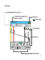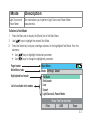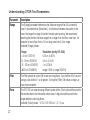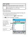
1
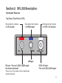
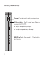
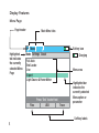
OFL 250
Handheld Single-mode OTDR
User’s guide
®
A
B
OFL 250
Handheld Single-mode OTDR
User’s guide
®
© 2007-2010, AFL Telecommunications, all rights reserved. OFL2-26-1000 Revision E 2010-12-02
Specifications are subject to change without notice.
C
D
Table of Contents
Safety Information......................................................................................... IV
Section 1: General Information
Contacting Customer Service.......................................................1
Recommended Accessories..........................................................1
Section 2: OFL 250 Description
Hardware Features.......................................................................3
Top Panel (Test Ports & VFL).....................................................3
Side Panel (USB & Power Ports)................................................4
Front Panel (Keys & Display)......................................................5
Using OFL 250 Keys....................................................................6
Display Features..........................................................................8
Menu Page...............................................................................8
Trace Page...............................................................................9
Section 3: Setting Up Your OFL 250 OTDR
Selecting a Test Mode..................................................................10
Available Test Modes................................................................10
Understanding OTDR Test Parameters..........................................12
Full Auto Mode Settings...............................................................13
I
End Locate Mode Settings............................................................14
Live Mode Settings......................................................................15
Expert Mode Settings...................................................................16
Events Menu Settings...................................................................17
Fiber Menu Settings.....................................................................18
Cables Menu Settings..................................................................20
General Settings..........................................................................21
Light Source & Power Meter Settings............................................22
Light Source Operation.............................................................22
Optical Power Meter Operation . ...............................................22
Section 4: Running Tests & Viewing Results
Starting and Stopping Tests..........................................................24
Selecting the Test View ...............................................................25
Trace Page Features....................................................................26
Event Table Page Features............................................................29
Event Icons and Types..............................................................30
Information Page Features............................................................31
Section 5: Saving & Reviewing Test Results
File Manager System....................................................................32
File Manager – Folders Page.....................................................33
File Manager – Files Page.........................................................34
II
File Manager – Save As Page....................................................35
Creating New Folders Using the Save As Page...............................37
Selecting a Folder as the Current Folder........................................37
Saving Test Results......................................................................37
Save Results to an Existing Folder ............................................37
Saving Results to a New Folder.................................................37
Opening Files (Reviewing Saved Results)......................................38
Deleting Files or Folders...............................................................38
Transferring Files to your PC.........................................................38
Section 6: Maintenance Tips
Cleaning......................................................................................40
Recharging Batteries....................................................................42
Repair and Calibration..................................................................42
How to View Version Information...................................................42
Appendix A: FAQs.......................................................................................... 43
Appendix C: Limited Warranty...................................................................... 44
III
Safety Information
WARNING! Use of procedures or adjustments other than those specified herein may result
in hazardous radiation exposure.
This is a CLASS I LASER output
1310/1550 nm
single-mode OTDR port
VFL port
This is a CLASS II LASER output. Do not stare into beam
WARNING! Do not connect the OTDR to any fiber that is not dark, or that is terminated by
a device with reflectivity > -13 dB.
CAUTION! To avoid serious eye injury, never look directly into the optical outputs of fiber optic
network equipment, test equipment, patch cords, or test jumpers. Refer to your company’s
safety procedures when working with optical systems.
WARNING! Use only the specified AC adapter. Use of another type of AC adapter can damage
the instrument and create the danger of fire and electrical shock.
IV
WARNING! To avoid the danger of fire and electrical shock:
•
Never use a voltage that is different from that for which the AC adapter is rated.
•
Do not plug the unit into a power outlet that is shared by other devices.
•
Never modify the power cord or excessively bend, twist, or pull it.
•
Do not allow the power cord to become damaged. Do not place heavy objects on the
power cord or expose it to heat.
•
Never touch the AC adapter while your hands are wet.
•
Should the power cord become seriously damaged (internal wiring exposed or
shorted), contact the manufacturer to request servicing.
CAUTION! Do not connect the OFL 250 OTDR test port to a live fiber.
If you are not certain that the fiber to be tested is ‘dark’ (not live), measure the optical
power level of the fiber before connecting to the OFL250 OTDR port. Use a jumper to
connect the OFL250 OPM test port to the fiber to be tested, set the OFL250 test mode
to OPM with units set to dBm. If the detected level is above -20 dBm, do not connect this
fiber to the OFL250 OTDR test port. Connecting the OFL250 OTDR test port to a live fiber
can cause a bad trace or in the worst case, damage the OTDR.
V
NOTICE: An OFL 250 OTDR contains no user serviceable parts. Except for changing batteries and
cleaning optical ports, this instrument must be returned to Noyes or authorized agents for repair and
calibration.
IMPORTANT: Proper care in handling should be taken when using any precision optical test equipment.
Scratched or contaminated optical connectors can impact the performance of the instrument. It is
important to keep the dust caps in place when the unit is not being used.
VI
Section 1: General Information
This User’s guide provides operating instructions for testing fiber optic networks with the OFL 250
OTDR and assumes that you have basic knowledge about testing fiber optic networks. The purpose
of this user’s guide is to explain how to use and maintain your OFL 250 OTDR. Please check our web
site at www.afltele.com/go/Noyes for updates to this manual, software updates, and additional
application information. If you have any questions about your OFL 250 and recommended accessories,
or if you need technical or sales support, please contact Noyes Customer Service.
Contacting Customer Service
You may call Noyes Customer Service between 8 AM and 5 PM, United States Eastern Time.
Phone800-321-5298
603-528-7780
Fax 603-528-2025
Mail: [email protected]
Recommended Accessories
You will need fiber optic test jumpers to connect your OFL 250 to the fiber under test. Test jumpers
must have the same core and cladding size as the fiber under test. The connector at one end of the
test cable must mate with the appropriate optical port on the OFL 250. The connector on the other
end must mate with the fiber optic link under test.
Launch and Receive cables are required to measure the insertion loss and reflectance of the nearend and far-end connectors respectively, on the fiber link being tested. Noyes Fiber Rings may be
1
used as Launch and Receive cables. Fiber Rings with a variety of lengths and connector styles are
available from AFL Telecommunications. The table below will help you to select right test jumpers or
cables for your test.
To do the following
2
You will need the following accessories
To connect your
OTDR to the fiber
link under test
To terminate far-end
of the fiber link under
test
• Fault locate - find a break
• Measure link length
Test Jumper
(1-2 m typical)
None
• Measure near-end connector loss
• Measure near-end connector reflectance
Launch cable
(such as a Noyes
150 m Fiber Ring)
None
• Measure near-end connector loss and
reflectance
• Measure far-end connector loss and
reflectance
• Measure end to end link loss and optical
return loss
Launch cable
(such as a Noyes
150 m Fiber Ring)
Receive cable
(such as a Noyes
150 m Fiber Ring)
Section 2: OFL 250 Description
Hardware Features
Top Panel (Test Ports & VFL)
Red colored bar indicates
the VFL test port
Blue colored bar indicates
the OPM test port
VFL
OPM
White colored bar indicates
the OTDR / OLS test port
OTDR OLS
OPM port
VFL port - This is a CLASS II LASER output.
Do not stare into beam!
This port is a VFL module, 650 nm Visible Fault
Locator (red laser).
OTDR / OLS port
This is a CLASS I LASER output
3
Side Panel (USB & Power Ports)
Power port - This is the interface for the AC power adapter/charger.
15V
AC/Charger indicator -  When ON, indicates that an AC adapter is
connected to the OFL 250 OTDR.
• Red light - rechargeable battery is charging.
• Green light - rechargeable battery is fully charged.
MINI-USB type B port - Allows connection to a PC for transferring
stored test results.
4
Front Panel (Keys & Display)
The OFL 250 front panel contains keys, indicator, and a display. The use of the [Power], [Menu],
[Test], [Back], [Save], and [VFL] keys are fixed. The use of the soft function keys and arrow keys
depend on which menu or editor submenu they are displayed.
Function of each key is explained in the section titled ‘Using OFL 250 Keys’.
Display - Used to show the
setup menus, test results,
and saved files information
Arrow keys
Select key
Soft function keys
Back /
Test
Back key
Test key
Menu
Save
Menu key
Save key
VFL
Power key
Left & Right Tab keys
OFL 250 OTDR
VFL key
VFL Indicator - Illuminates
when the VFL port is active
5
Using OFL 250 Keys
The use of each key is summarized in the table below.
Key Symbol Key Name
6
Key Function
Power
Press and hold (approx. 1 sec.) to turn the OFL 250 on or off.
VFL laser
ON - Press and hold (approx. 2 sec.), VFL indicator will turn on and flash.
OFF - Press and hold (approx. 1 sec.), VFL indicator will switch off.
Menu
Press to access the Main Menu.
Left and
Right
Tab keys
Press to display the next/previous available Menu Tab or Test View
Tab.
Arrow keys
(Navigation
Keys)
The arrow keys provide several functions as follows:
• In the Main Menu, these keys are used to navigate menus
and change setup parameters.
• In the Trace Page:
In the Zoom mode, these keys are used to adjust zoom.
In the Move mode, Left and Right keys are used to move
cursors.
Select
This key provides several functions as follows:
• In the Main Menu, press this key to display a
submenu (if available).
• In the Trace Page, press this key to toggle
between [A] and [B] cursor.
Back
Press once to return the previous page.
Press one or more times, depending on which menu or editor
submenu is displayed, to return to the Main Menu.
Test
Press to start or stop a test.
Save
Press to save the currently displayed test results.
Soft
function
keys
The label shown above each key on the display indicates the
current use of each function key. Press to activate the currently
designated function.
7
Display Features
Menu Page
Page header
Main Menu tabs
Main Menu
Highlighted
tab indicates
the currently
selected Menu
Page
Mode Settings About
Full Auto
End Locate
Live
Expert
Light Source & Power Meter
Files
8
Battery icon
Press ‘Test’ to start test
USB
Trace
- Charging
Menu area
Highlighted bar
indicates the
currently selected
Menu option or
parameter
Soft key labels
Trace Page
Test Wavelengths (BLUE is current)
File name (for not saved file, will
display “New Trace”)
Battery icon
- Fully charged
CABLE000_001
i
1310 1550
Test Viewer tabs
Results area
A
A
0.0000
00.000
WAVE
B 0.0000
LOSS
0.00
ZOOM
A B 0.0000 km
REFL 000.0 dB
UNZOOM
Soft key labels
9
Section 3: Setting Up Your OFL 250 OTDR
Selecting a Test Mode
Available Test Modes
The OFL 250 OTDR offers five modes of operation: Full Auto, End Locate, Live, Expert, and Light Source
& Power Meter mode. The Mode setting determines which other settings may be changed by the user
and which are set by the OFL 250 automatically. Each OFL 250 mode is described below:
Mode
Description
Full Auto
This is the recommended mode for users who are not familiar with OTDR
operation. In the Full Auto mode, OTDR parameters such as Range, Filter,
Pulse Width, and Averaging Time are set automatically. Full Auto tests include
an Event Table and Information Page.
End Locate
As in the Full Auto mode, End Locate mode offers automatic OTDR setup but
replaces the Event Table view with the End Locate view to indicate the fiber
end location in user selected units of measure.
Live
This is the best mode for real-time troubleshooting. In the Live mode,
Wavelength can only be set to individual wavelengths.
Expert
This mode is available for experienced users. It provides the most set
up flexibility. You can set Range, Filter, Pulse Width, and Averaging Time
manually (Auto Setup = Off) or automatically (Setup = By Range).
10
Mode
Light Source and
Power Meter
Description
This mode allows you to perform Light Source and Power Meter
measurements.
To Select a Test Mode
1. Press the Menu key to display the [Mode] tab of the Main Menu.
2. Use [
] keys to highlight the desired Test Mode.
3. Press the Select key to display a settings submenu for the highlighted Test Mode. From this
submenu:
• Use [
] keys to highlight the desired parameter.
• Use [
] keys to change the highlighted parameter.
Page header
Main Menu tabs
Highlighted test mode
List of available test modes
Main Menu
Mode Settings About
Full Auto
End Locate
Live
Expert
Light Source & Power Meter
Files
Press ‘Test’ to start test
USB
Trace
11
Understanding OTDR Test Parameters
Parameter
Description
Range
The [Range] parameter determines the distance range of the full (unzoomed)
trace. It also determines [Resolution] - the distance between data points in the
trace: the longer the range, the wider the data point spacing. We recommend
selecting the shortest distance range that is longer than the fiber under test. For
example, to test a fiber that is 1.5 km long, select the 2.5 km range.
Available [Range] values:
Range
Resolution (set by OFL 250)
< 4 km (13123 ft)
0.25 m (0.82 ft)
8 - 16 km (26246 ft)
0.5 m (1.64 ft)
16 - 32 km (52493 ft)
1 m (3.28 ft)
32 km (104986 ft)
range/ 1600 m (range/ 5249 ft)
Filter
The Filter should be turned ON to test very long fibers. Turn the filter ON if you are
using a pulse width of 1 us or greater. Turning the [Filter] ON makes a choppy or
noisy trace smoother.
Pulse
The OFL 250 can operate using different pulse widths. Short pulse widths provide
the shortest event and attenuation dead zones. Long pulse widths provide the
range needed to test long fibers.
Available [Pulse] values: 10, 30, 100, 300 ns, 1, 3, 10 ms.
12
Parameter
Description
Averaging
The [Averaging] parameter determines the duration of a timed test and the
number of trace averages performed. The longer the test the smoother the trace.
Available [Averaging] values: 5, 10, 30, 60, 90, 180 sec.
Full Auto Mode Settings
In the Full Auto test mode, you may select the desired test wavelengths while the [Range], [Filter],
[Pulse], and [Averaging] parameters are set by the OFL 250.
1. From the displayed [Full Auto] submenu, use [
2. Use [
] keys to highlight [Wavelength].
] keys to select a single wavelength or dual wavelength.
Use Left / Right arrow
key to select the desired
single wavelength or dual
wavelengths
Set by OFL 250
Full Auto
Test Event Fiber Cables
Wavelength
Auto Setup
Range
Filter
Pulse
Averaging
Files
1310/ 1550 nm
On
Auto
Auto
Auto
Auto
Press ‘Test’ to start test
USB
Trace
13
End Locate Mode Settings
As in the Full Auto mode, End Locate mode offers automatic OTDR setup but replaces the Event Table
view with the End Locate view to indicate the fiber end location in user selected units of measure. In
the End Locate mode, the End Locate view is always shown after a test is started.
End Locate view tab
CABLE000_001
i
1550
Trace Graph
End location in user selected units
End: X.X m
ZOOM
14
UNZOOM
Live Mode Settings
In the Live test mode, you may set to {Off] or [By Range].
•
[Off]: Setting the [Auto Setup] parameter to [Off], allows you to set the [Range], [Filter], and
[Pulse] parameters while the [Averaging] parameter is set by OFL 250.
•
[By Range]: Setting the [Auto Setup] option to [By Range], allows you to set the [Range]
parameter while the [Filter], [Pulse] and [Averaging] parameters are set by OFL 250.
To Set Live Mode Parameters
1. From the displayed [Live] mode submenu, use [
2. Use [
] keys to highlight the desired parameter.
] keys to change the highlighted parameter..
Set the desired test wavelength
If set to [By Range], set [Range]
while the OFL 250 sets the
[Filter], [Pulse], and [Averaging]
If set to [Off], set [Range], [Filter],
[Pulse], and [Averaging]
Use Left / Right arrow key to
change highlighted parameter
Live
Test
Event Fiber Cables
Wavelength
Auto Setup
Range
Filter
Pulse
Averaging
Files
1550 nm
By Range
250 m
Off
10 ns
Auto
Press ‘Test’ to start test
USB
Trace
15
Expert Mode Settings
In the Expert test mode, you may set to [Off] or {By Range].
•
[Off]: Setting the [Auto Setup] parameter to [Off], allows you to set the [Range], [Filter],
[Pulse], and [Averaging] parameters.
•
[By Range]: Setting the [Auto Setup] option to [By Range], allows you to set the [Range]
parameter while the [Filter], [Width], and [Averaging] parameters are set by the OFL 250.
To Set Expert Mode Parameters
1. From the [Expert] mode submenu, use [
2. Use [
] keys to highlight the desired test parameter.
] keys to change the highlighted parameter.
Choose a single wavelength or
dual wavelengths
Live
Test
Event Fiber Cables
If set to [Off], set [Range],
[Filter], [Pulse], and [Averaging]
Wavelength
Auto Setup
Range
Filter
Pulse
Averaging
Use Left /Right arrow key to
change highlighted parameter
Files
If set to [By Range], set [Range]
while the OFL 250 sets the
[Filter], [Pulse], and [Averaging]
16
1550 nm
By Range
250 m
Off
10 ns
Auto
Press ‘Test’ to start test
USB
Trace
Events Menu Settings
Events settings are available in the [Full Auto], [End Locate], and [Expert] test modes.
•
In the [Full Auto] test mode, the [Events] parameter is set to [Auto] by default with the
[Thresholds] parameter available as [Default] or [User] selectable.
•
In the [Expert] test mode, the [Events] parameter may be set to [Auto] or [Off]. If set to [Auto],
the [Thresholds] parameter is available as [Default] or [User] selectable.
Event Thresholds in Full Auto and Expert test modes
Threshold
Min Value
Default Value
Max Value
End Loss, dB
1.0 dB
3.0 dB
6.0 dB
Event Loss, dB
0.02 dB
0.10 dB
2.00 dB
Event Reflectance, dB
-10.0 dB
-50.0 dB
- 65.0 dB
•
In the [End Locate] test mode, the [Events] parameter is set to [End Locate] by default with the
[Thresholds] parameter available as [Default] or [User] selectable.
Event Thresholds in End Locate test mode
Threshold
Min Value
Default Value
Max Value
Event Loss, dB
1.0 dB
3.0 dB
6.0 dB
17
To Set Events
1. From the Main menu, use [
] keys to display the [Event] page.
2. From the displayed [Event] page, use [
3. Use [
] keys to highlight the desired parameter.
] keys to change the highlighted parameter.
Use Left / Right arrow key to
display the desired option
Use Left /Right arrow key to
change highlighted parameter
Expert
Test Event Fiber Cables
Events
Thresholds
End Loss, dB
Event Loss, dB
Event Reflectance
Files
Auto
User
3.0
0.79
-50.0
Press ‘Test’ to start test
USB
Trace
Fiber Menu Settings
The Fiber menu allows selecting the [Fiber Type] parameter between [Default] and [User]:
•
[Default - SMF-28e] - sets the default Index (Group Index of Refraction) and BC (Backscatter
Coefficient) values to those of SMF-28e type fiber
•
[User] - allows entering user selectable Index (Group Index of Refraction) and BC (Backscatter
Coefficient) values
18
Note:
Using the [Default] Index and BC values is generally recommended.
Enter the [User] Index and BC values only if you know the specifications of the particular fiber you are
testing and these specifications are significantly different from the default SMF-28e numbers.
To Set Fiber Parameters
1. From the Main menu, use [
] keys to display the [Fiber] page.
2. From the displayed [Fiber] page, use [
3. Use [
] keys to highlight the desired parameter.
] keys to change the highlighted parameter.
Use Left /Right arrow key to
toggle [Default] and [User]
options
Use Left /Right arrow key to
change highlighted parameter
Expert
Test Event Fiber Cables
Fiber Type
Index @1310
BC @1310, dB
Index @ 1550
BC @1550, dB
Files
SMF-28e
1.4677
-77.0
1.4682
-82.0
Press ‘Test’ to start test
USB
Trace
19
Cables Menu Settings
Note: Launch and Receive cables are required to measure the insertion loss and reflectance of
the near-end and far-end connectors respectively, on the fiber link being tested. See section titled
“Recommended Accessories” for details.
To Set Launch and Receive Cable Parameters
1. From the Main menu, use [
] keys to display the [Cable] page.
2. From the displayed [Cable] page, use [
3. Use [
] keys to highlight the desired parameter.
] keys to change the highlighted parameter.
Use Left /Right arrow key to
display the desired option
Use Left/ Right arrow key to
define the [User] launch cable
Length
Expert
Test Event Fiber Cables
Launch Cable
Launch Length
Receive Cable
Receive Length
Default
150.0 m
User
51.7 m
Use Left /Right arrow key to
display the desired option
Use Left/ Right arrow to define
the [User] receive cable Length
20
Files
Press ‘Test’ to start test
USB
Trace
General Settings
Main Menu: General Settings Page
The General Settings page contains units of measurement distance settings that impact how new and
saved test results are displayed. This page also contains time & date setup functions that need to be
performed when you first receive your OFL 250 OTDR.
Changes made to distance units will impact currently viewed results and future tests.
1. From the Main menu, use [
2. Using use [
] keys to display the [Settings] page.
] keys navigate up/down the list to highlight the desired parameter.
3. For [Distance units]: use [
] keys change the [Distance units] parameter.
4. For [Date & Time]: press the Select key to display the [Date & Time] submenu.
• Use [
] keys to highlight the desired parameter.
• Use [
] keys to change the highlighted parameter.
Software and Optic Version Information
1. Using [
] keys scroll through Main menu tabs to display [About].
• The [OFL 250 Version] parameter displays the software version number.
• The [Optic Version] displays the version of the optics module.
21
Light Source & Power Meter Settings
Light Source Operation
After enabling the Light Source & Optical Power Meter test mode or turning the [Laser] option On, let
the laser stabilize for approximately five minutes.
1. Use [
] keys to highlight the desired light source setup parameter.
2. Use [
] keys to change the highlighted parameter.
• Turn the current light source laser on or off.
• Set up the light source for CW (continuous wave), 1 kHz , 2 kHz tone, or Wave ID operation.
• Set up the light source for 1310 or 1550 nm operation.
Optical Power Meter Operation
1. Press the [Ref/Set] soft key to see the Reference value (in dBm) for several seconds, then
display will return to dB mode.
2. To set a new OPM reference level, hold the [Ref/Set] key until you see REFERENCE [SAVED].
This takes about one second.
3. When you release the [Ref/Set] soft key, the unit should display the current loss value in dB.
4. You can sample and hold live POWER or LOSS readings by pressing the [Test] key. While a
held value is shown you will see POWER [ STOPPED] or LOSS [STOPPED].
5. Press the Test key again to return to the live data view.
22
Light Source settings
Use Left /Right arrow key
to turn the laser On or Off
Light Source & Power Meter
SOURCE
Use Left /Right arrow key to
display the test mode:
CW, 1 kHz tone, 2 kHz tone,
or Wave ID
Laser
On
Mode
Wave ID
Wavelength
1550 nm
METER
Use Left /Right arrow
key to select the desired
wavelength
POWER
1310 nm
XX.XX dBm
Press ‘Test’ to start test
dB / dBm / W
Ref / Set
OPM key
Press the dB/dBm/W key to toggle the OPM
units. Select dB to measure loss. Select
dBm or W (watts) to measure power
OPM key
REFERENCE key.
Press to set OPM
reference level
λ
OPM key
Press the l key to toggle
the OPM wavelength
23
Section 4: Running Tests & Viewing Results
Starting and Stopping Tests
To Start a Test
•
Press the
- Test key
To Stop a Test
•
Press the
- Test key. If pressed before trace appears will stop the test and display the
setup menu. If pressed after trace appears it will stop the test and show the partially completed
trace.
•
Press the
Back key. The OFL 250 stops the test and displays the setup menu.
How can I tell if a test is running?
The OFL 250 Page header will display the [Testing] label and Test in Progress icons:
Test in Progress icons
Testing label
Testing
1310 1550
How can I tell if a test is done?
The OFL 250 Page header will display the [New Trace] label.
24
i
Selecting the Test View
The OFL 250 test results can be displayed in one of three different Views or Pages. Each Page
presents a different view of the current or saved test. Each Page is identified by the corresponding
tab as illustrated below.
Page tabs
CABLE000_001
1310 1550 1625
i
To display the desired Page for viewing, use Left and Right Tab keys
Test Views (Pages) Description
Tab
i
Name
Description
Trace
Displays OTDR trace, A/B cursors, Loss and Distance between A & B
cursors, and reflectance.
Event Table
Displays OTDR trace and events data: location in user selected units of
measure, type, reflectance and insertion loss in dB.
Information
Displays OTDR setup parameters, launch and receive cables data, and
events data.
Refer to sections titled “ Trace Page Feature”, “Zoom Adjust”, “Event Table Page Features”, and
“Information Page Features” for details.
25
Trace Page Features
The illustration below and table on the right describe the Trace Page features.
7
CABLE000_001
6
8
i
1310 1550
10
9
11
13
12
Active cursor is
highlighted
1
2
A
A
0.0000
00.000
WAVE
For dual-wave tests,
press to toggle the
displayed test results
26
B 0.0000
LOSS
0.00
ZOOM
A B 0.0000 km
REFL 000.0 dB
3
4
UNZOOM
Press to Unzoom/Rezoom
5
Highlighted block indicates the
currently selected Vertical Zoom
mode
Trace Page Features Description
Ref
Feature
Description
1
Trace
This is a graph of insertion loss vs. distance. The vertical axis shows loss in
dB. The horizontal axis shows distance in user-selected Distance units.
2
Cursors
Used to measure loss, and distance. The active cursor can be moved by
pressing the [
] arrow key. Press the
-[Select] key to toggle
between the A and B cursors. Active cursor is RED, inactive cursor is
BLACK.
3
Cursor data
row
This row displays A cursor location, B cursor location, and distance from A
to B in user-selected Distance units.
4
Test data
row
This row displays backscatter level at the A cursor, the two-point Loss from
A to B - [LOSS] and the maximum reflection between the two cursors [REFL] in dB.
5
[Zoom] /
In Trace View, this key is used to toggle between [Move] mode - move the
[Move] soft active cursor and [Zoom] mode - adjust horizontal and vertical zoom levels.
function key In the [Move] mode, the key label will be displayed as [
Zoom]
In the [Zoom] adjust mode, the key label will be displayed as [ x Zoom]
continued on the next page
27
Ref
Feature
Description
6
Wavelength
field
Displays test wavelengths of the currently displayed trace.
For the dual-wavelength test (1310/1550 nm), press the [Wave] soft key to
toggle between the 1310 nm and 1550 nm test results respectively.
Note: the currently displayed wavelength is RED
7
File name
field
Displays file name of the currently displayed trace. If a trace is not saved,
will display the [New Trace] label.
8
Battery
indicator
Displays estimated battery status as follows:
Green battery icon - battery is full
Black battery icon - battery requires recharging
28
9
Page icons
The Highlight box around an icon indicates the active view.
10
Front Panel
Offset
(FPO)
The first (amber) area shows the front panel offset (FPO), which is the
distance from the start of the trace (first data point) to the front panel
connection to the OTDR. FPO is typically 8 m for the OFL 250.
11
First Event
Event at front panel of OTDR.
12
User Offset
(UO)
The second (gray) area shows the launch cable length, also known as the
user offset (UO).
13
Event
Event at start of fiber under test.
Event Table Page Features
Event Table is always generated if testing in the [Full Auto] or [End Locate] modes, and optional in
the [Expert] test mode.
1. In the [Full Auto] and [End Locate] modes, [Events] are set to [Auto] by default.
2. In the [Expert] test mode, set Events (Events menu) to Auto.
CABLE000_001
i
1310 1550
Trace Graph
Event Table displays:
events location in user selected
units, event type, reflectance
and loss in (dB)
No Location Type
(m)
1
xxxx
2
xxxx
WAVE
Refl
(dB)
xxxx
xxxx
Loss
(dB)
xxxx
xxxx
ZOOM
29
Event Icons and Types
Icon
Event Type
Description
Start
The start of the fiber under test.
End
The end of the fiber under test.
Reflective
Event
An event with measurable loss and reflectance, typically caused by a
connection or mechanical splice.
Non-Reflective An event with measurable loss but very small or unmeasurable
Event
reflectance, typically caused by a splice or bend in the fiber.
30
Gainer
An event with ‘negative loss,’ which can occur in OTDR traces where
two fibers with very different backscatter coefficients are spliced or
connected. Normally a gainer will be seen as a normal (positive loss)
event when tested from the other end of the fiber. The true loss of the
event causing the gainer is the approximately equal to the average of
its loss measured from each end of the fiber under test.
Multiple Event
An event table entry that accounts for two or more physical (real)
events that are too close together to be measured separately by the
OTDR, for example the start and end of a short jumper. The loss of
a multiple event is the sum of the losses of the physical events that
comprise it.
Information Page Features
The OFL 250 generates and displays the information page with every OTDR Test mode selected. This
page displays how the test was created.
•
You may change the Index of Refraction and Launch Cable to correct locations in the Event
Table after the test is complete.
•
You may also change Thresholds and then recalculate the event table by pressing the [CALC
EVENT] soft key.
New Trace
1310 1550
Use the Left/ Right arrow key to
change the highlighted parameter
Use the Left/ Right arrow key to
change the highlighted parameter
These fields show the current
test data
Index
BC, dB
Launch Cable
Receive Cable
Events
End Loss, dB
Event Loss, dB
Event Reflectance
Mode: Full Auto
Range: 500m
Filter: Off
WAVE
For dual-wave tests, press to toggle the
displayed test results
1.4677
-77.0
150.0 m
0.0 m
Auto
3.1
2.00
-50.0
Pulse: 30 ns
Avg Time:10 sec
Averages: 2424
CALC EVENT
Press to recalculate the
Event Table
31
Section 5: Saving & Reviewing Test Results
File Manager System
The OFL 250 File Manager system consists of three pages as follows:
Page
Name
Description
Function
Folders page
Displays a list of saved folders in
the OFL 250 internal memory
Used to select the current folder or delete
folders
Files page
Displays a list of saved files in the
current folder
Used to open or delete previously saved
test results, copy files, and save the
currently displayed test results to an
existing folder
Save As page
Displays the current folder and
file name
Used to name and save current test results
to an existing or a new folder
To display File Manager, press the [Files] soft key on the Main Menu page or when it appears.
continued on the next page
32
File Manager – Folders Page
To display [Folders] page:
•
Press the [Files] soft key. Depending on the prior settings, the File Manager will be displayed
as [Folders] or [Files] page.
•
If the [Files] page is displayed, indicate the (
•
Press the [Select] soft key to display [Folders] page.
Shows the highlighted folder data
2 - number of the selected folder
5 - total number of saved folders
Memory usage data
File Manager
NEWFOLDER001
NEWFOLDER002
NEWFOLDER003
NEWFOLDER004
NEWFOLDER005
Currently indicated folder
List of saved folders
“/” symbol indicates the
[Folders] page
Press to change the folder or file name
after a test has been completed. Once
satisfied, press the [Save] soft key
Hold (approx. 1 sec) to delete the
selected folder
..) symbol at the top of any [Files] page.
/
Save As...
2/5
Delete
Free: 99%
Open
Press to make the
indicated folder current
33
File Manager – Files Page
To display [Files] page:
•
Press the [Files] soft key. Depending on the prior settings, the File Manager will be displayed
as [Folders] or [Files] page.
•
If the [Folders] page is displayed, select the desired folder from the displayed list of folders.
•
Press the [Select] soft key to open the selected folder and display the [Files] page.
Memory usage data
Shows the highlighted file data:
(3) - number of the selected file
(4) - total number of saved files
in the currently open folder
Select ( ..) to display Folders
Page and see a list of folders
List of saved files
Name of the currently open
folder
34
File Manager
..
CABLE000_001
CABLE000_002
CABLE000_003
CABLE000_004
/NEWFOLDER001
Save As...
Press to change the
folder or file name
after a test has been
completed
3/4
Delete
Hold (approx. 1
sec.) to delete
the selected file
Free: 99%
Open
Press to review
test results of the
selected trace file
File Manager – Save As Page
The [Save As] page allows you to save current test results and create new folders if needed. This
page allows you to review and if needed change the file and folder names each time test results are
saved.
1. To display the [Save As] page, press the [Save] key or the [Save As] soft key when it appears.
2. When the [Save As] page is displayed, use [
] keys to indicate (highlight) any character
position within the Folder name field or File name field.
3. Use [
] keys to change the highlighted character.
• If the Folder name is edited to a name that already exists, then pressing the [Save] (soft or
hard) key will save the current test results in this folder and make this folder current.
• If the File name is edited to a name that already exists in the current folder, then pressing
the [Save] key will cause the OFL 250 to display “Overwrite file?”. Press [Cancel] to stop
the save process or [Yes] to overwrite the previously saved file.
• If the Folder name is edited to a new name, then pressing the [Save] key will cause the
OFL 250 to create a new folder of this name. Note: This is the only way to create new
folders!
see illustration on the next page
35
Highlighted block indicates the
currently selected character
Folder name FIELD - user set.
Use Up & Down Arrow keys to
change
File name FIELD - user set.
Use Up & Down Arrow keys to
change
Save As...
Folder:
NEWFOLDER001
File name
CABLE000_001
Fiber number - user set, will
auto increment
Current Folder / File name that
will be used next time you press
the [Save] soft key
/NEWFOLDER000/CABLE000_001
Files
Cancel
Save
Press to display the File
Manager page
Press to exit Save As page
36
Press to save with the
currently displayed
Folder / File name
Creating New Folders Using the Save As Page
New Folders are created in the File Manager - [Save As] page. See section above ‘File Manager Save As Page’.
Selecting a Folder as the Current Folder
1. Access the File Manager - [Folders] page.
2. Use [
] keys to highlight the desired folder.
3. Press either [Select] key or [Open] soft key to make the indicated folder current.
Saving Test Results
Test results are stored on the OFL 250 Internal Drive. Results are saved as industry standard .SOR
files, which can be viewed, printed, and analyzed on a PC using Trace.net software.
Save Results to an Existing Folder
To save the currently displayed test results to an existing folder, perform the following steps:
1. Once a test is complete, press the [Save] key. The [Save As] page will be displayed.
2. From the displayed [Save As] page, press the [Save] key to save with the currently displayed
Folder/ File name.
Saving Results to a New Folder
To save test results to a new folder, use the File Manager - [Save As] page.
1. Once a test is complete, press the [Save] key to display the [Save As] page.
37
2. Edit the File or Folder name, or select an existing folder and enter a new File name, as
described in the section titled ‘File Manager - Save As Page’.
3. When done, press either soft or hard [Save] key.
Opening Files (Reviewing Saved Results)
1. Access the File Manager - [Files] page.
2. Use [
] keys to highlight the desired file.
3. Press the [Open] soft key to display test results.
Deleting Files or Folders
1. Access the File Manager - [Files] / [Folders] page.
2. Use [
] keys to highlight the desired file / folder.
3. Press and hold the [Delete] soft key for about one second to delete the selected file/ folder.
Transferring Files to your PC
To transfer files from your OFL 250 to a PC using a USB cable, perform the following:
1. Connect your OFL 250 to a PC using a type A to Mini USB B cable. Make sure the mini-plug is
fully seated in your OFL 250.
2. Press the [USB] soft key on the OFL 250.
3. On your PC, open My Computer. A new removable drive named [OFL X:] will appear, where ‘X:’
38
is the drive letter assigned to your OFL 250.
4. Under [OFL X:] you should see two folders: [RESULTS] and [SOFTWARE].
5. Copy the [RESULTS] folder to your PC.
6. Under [RESULTS] you will see: [TRACES]
7. Under [TRACES] you will see all of the folders containing traces.
Note:
Before removing the USB cable connecting your OFL 250 to your PC, or pressing the [Cancel] soft
key on the USB page, left click the Safely Remove Hardware icon in the Start bar of your PC, then
left click the [Safely remove USB Mass Storage Device – Drive (X:)] message, where ‘X’ is the drive
letter assigned to your OFL 250.
39
Section 6: Maintenance Tips
Cleaning
Cleaning Test Cables and FUT
Connector end faces must be kept free from dirt or other contaminates to ensure accurate measurements
and operation. It is important to keep connectors on the launch and receive cables and those on the
Fiber Under Test (FUT) clean. Follow your company’s approved cleaning procedures.
Cleaning the Optical Ports
CAUTION! Before conducting the following procedures be sure to have the OFL 250 turned OFF.
To access the SM OTDR Port:
•
Rotate the adapter base counterclockwise approximately four times.
•
Pull the adapter directly out away from the universal adapter mount.
To access the VFL Port:
•
40
Unscrew the adapter counterclockwise and pull the adapter straight out to expose the ferrule.
Cleaning the Exposed Ferrule (two methods)
I. Noyes Cleaning Procedure
•
•
•
•
•
II. If using lint-free optical cleaning pads
and isopropyl alcohol
Lean a can of FCC2 back (30°), press the
•
button on FCC2 to fill the well.
Dip a CCTP stick into the well of the FCC2 to •
dampen the tip with optical cleaning fluid.
Place the damp tip over the ferrule to be
cleaned.
Rotate the tip clockwise 10 revolutions while
applying varying pressure to create a gentle
pumping action where the tip contacts the
ferrule.
Discard the CCTP stick after using both tips.
Be sure to use 99% IPA that has not
been contaminated.
Dampen the wipe with the alcohol and
gently wipe the exposed ferrule. Then
dry the ferrule using a new optical wipe.
Cleaning the adapters
•
Use a can of filtered compressed air (held vertically), blow out any contaminants from the
adapter.
•
Once completed, replace the adapter over the ferrule, centering it onto the alignment pin.
•
Tighten the adapter base.
41
Recharging Batteries
You may charge the batteries while the OFL 250 is switched on or off by attaching an AC power
adapter.
•
Plug the AC adapter/charger into a standard wall outlet.
•
Connect the AC adapter/charger to the Power port located on the OFL 250 side panel.
•
The [AC/Charger] indicator on the side panel will turn on - Red.
•
Charge batteries until the [AC/Charger] indicator turns Green.
Repair and Calibration
Unauthorized repair of the Noyes test equipment will void the warranty.
Calibration is recommended every 3 years. Noyes Calibration department is in compliance with ANSI/
NCSL Z540-1, ISO 10012-1, MIL STD 45662A, ISO Guide 25 and traceability to the National Institute
of Standards and Technology. Call Customer Service to obtain a Service Request (SR) Number before
sending units in for calibration.
How to View Version Information
From the Main Menu, use [
software version number.
] keys to open the [About…] menu and display the OFL 250
Note: It is helpful to have the OFL 250 version number if you need to contact Noyes Customer Service
or Technical Support.
42
Appendix A: FAQs
Can I save traces for viewing later?
Yes. There is a dedicated [Save] key. After you press the [Save] key, you can set file name and
folder.
Can I create a new folder?
Yes. Press the [Save] key, then enter a new folder name, and then press the [Save] key again.
What is the purpose of the Live Mode?
With a launch cable, the Live or “real-time” mode may be used to quickly view many short fiber links.
It can also be used to quickly “trace” short fiber link fibers.
Why do I need to use a launch and receive cable?
A launch cable allows the OTDR to settle down after the initial pulse and provides a reference cable
for testing the first connector on the fiber under test. A receive cable provides a reference cable for
testing the last connector of the fiber under test.
43
Appendix C: Limited Warranty
Warranty
Returning Equipment
All AFL/Noyes test equipment products are
warranted against defective material and
workmanship for a period of (1) one year from
the date of delivery to the end user. Extended
warranties start at the end of the standard (1) one
year warranty period. Any product that is found
defective within the warranty period will, at the
discretion of AFL/Noyes, be repaired or replaced.
Warranty will be voided if the product has been
repaired or altered by other than an authorized
AFL/Noyes repair facility or which have been
subject to misuse, negligence, or accident.
To return equipment, please contact Noyes
to obtain additional information and a Service
Request (S.R.) number. To allow us to serve
you more efficiently, please include a brief
description specifying the reasons for the return
of the equipment.
CE Information
These instruments have been
designed and tested to comply
with the relevant sections of any
applicable specifications including
full compliance with all essential requirements
of all applicable EU Directives.
44
AFL Telecommunications
Noyes Test & Inspection
16 Eastgate Park Road
Belmont, NH 03220
Tel:
800-321-5298
603-528-7780
Fax: 603-528-2025
Thank you for choosing Noyes Test & Inspection
N OY E S
16 Eastgate Park Road
ISO
Belmont, NH 03220
9001
Phone:800-321-5298
C E RT I F I E D
603-528-7780
Fax: 603-528-2025
www.AFLtele.com > Products > Noyes Test & Inspection
®
45