1
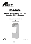
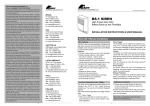
ELECTRONIC ENGINEERING LTD. OLED Keypad User’s Guide P/N: 7103670 Doc Rev-A SW Ver-0.65 05/08/10 Crow Limited Warranty Crow warrants this product to be free from defects in materials and workmanship under normal use and service for a period of one year from the last day of the week and year whose numbers are printed on the printed circuit board inside his product. Crow’s obligation is limited to repairing or replacing this product, at its option, free of charge for materials or labor, if it is proved to be defective in materials or workmanship under normal use and service. Crow shall have no obligation under this Limited Warranty or otherwise if the product is altered or improperly repaired or serviced by anyone other then Crow. There are no warranties, expressed or implied, of merchantability or fitness for a particular purpose or otherwise, which extend beyond the description on the face hereof. In no case shall Crow be liable to anyone for any consequential or incidental damages for breach of this or any other warranty, expressed or implied, or upon any other basis of liability whatsoever, even if the loss or damage is caused by Crow’s own negligence or fault. Crow does not represent that this product can not be compromised or circumvented; that this product will prevent any person injury or property loss or damage by burglary, robbery, fire or otherwise; or that this product will in all cases provide adequate warning or protection. Purchaser understands that a properly installed and maintained product can only reduce the risk of burglary, robbery or other events occurring without providing an alarm, but it is not insurance or a guarantee that such will not occur or that there will be no personal injury or property loss or damage as a result. Consequently, Crow shall have no liability for any personal injury, property damage or any other loss based on claim that this product failed to give any warning. However, if Crow is held liable, whether directly or indirectly, for any loss or damage arising under this limited warranty or otherwise, regardless of cause or origin, Crow’s maximum liability shall not in any case exceed the purchase price of this product, which shall be the complete and exclusive remedy against Crow. © 2010. All rights reserved. Information in this document is subject to change without notice. No part of this document may be reproduced or transmitted in any form or by any means, electronic or mechanical, without express written permission of Print version 001 Contents KEYPAD DESCRIPTION ........................................................................................................................3 FUNCTION KEYS................................................................................................................................... 3 ALPHANUMERIC KEYS ............................................................................................................................ 4 AUDIBLE SIGNALS ................................................................................................................................ 4 INDICATORS ....................................................................................................................................... 4 SUMMARY OF FUNCTIONS ....................................................................................................................... 4 OPERATING THE KEYPAD ....................................................................................................................7 HOW TO ARM THE SYSTEM BEFORE EXIT..................................................................................................... 7 Preparing the System for Arming ...........................................................................................................7 Arming the System .................................................................................................................................7 Quick Arm (When enabled at installation) ..............................................................................................8 Disarming the System ............................................................................................................................8 Stopping and Resetting Alarms..............................................................................................................8 ARMING THE SYSTEM WHILE STAYING HOME ............................................................................................... 9 Arming the System in Stay Mode ...........................................................................................................9 Disarming the System ............................................................................................................................9 HOW TO BYPASS ZONES ........................................................................................................................10 USING CHIME (IF ENABLED AT INSTALLATION) ............................................................................................11 EMERGENCY ALERTS ............................................................................................................................12 How to initiate Panic .............................................................................................................................12 How to initiate Medical Alarm ...............................................................................................................12 How to initiate Fire Alarm .....................................................................................................................12 GENERATE THREAT OR DURESS ...............................................................................................................12 SYSTEM MESSAGES ..............................................................................................................................12 HOW TO READ TROUBLE MESSAGES AND EVENTS FROM MEMORY .....................................................................13 SPECIAL INDICATIONS ..........................................................................................................................13 HOW TO CONTROL OUTPUTS AND DEVICES ................................................................................................14 ENTERING THE USER PROGRAM/CLIENT MODE ............................................................................................15 HOW TO CHANGE OR ADD CODES ............................................................................................................15 About Master Code and the User Code ...............................................................................................15 How to Change the Master Code .........................................................................................................15 How to Add or Change the User Code.................................................................................................15 How to Delete the User Code...............................................................................................................16 ADDING/CHANGING TELEPHONE NUMBERS .................................................................................................16 HOW TO SET TIME AND DATE .................................................................................................................16 HOW TO START WALK TEST MODE ...........................................................................................................16 HOW TO ANSWER AN IN-COMING CALL .....................................................................................................17 USING THE REMOTE COMMAND CONTROL ..................................................................................................17 USING LOCAL COMMAND CONTROL ..........................................................................................................18 LCD KEYPAD IN LOCAL EDIT MODE ..........................................................................................................19 Accessing Local Edit Mode ..................................................................................................................19 Edit Names at Local Edit Mode ............................................................................................................20 Button Assignment ...............................................................................................................................21 Changing Language .............................................................................................................................22 Adjusting Backlighting ..........................................................................................................................22 Resetting All Text to Default.................................................................................................................23 i Keypad Description Copying Text to another LCD or OLED Keypad ..................................................................................24 Exiting Local Edit Program Mode .........................................................................................................24 ii Keypad Description The OLED Keypad shows all the information required to operate the system. The User communicates with the alarm system via the keypad. The Keypad displays continuous information about the status of the alarm system and enables the User to operate the system in different modes, change settings and program Users access codes. The keypad also collects and records events to be displayed afterward on request, to overview system activities and to analyze system performance for diagnostics. ARM ARM/READY LED STAY TROUBLE LED MENU OPEN ZONES STATUS HELP Function Keys These keys are used to arm the system, enter commands to alter system settings, or scroll through the history events. ARM, STAY, BYPASS, PROGRAM, CONTROL, MEMORY, PANIC, ENTER, MENU, , , , - these buttons are pre-programmed: - Arm Area A - Arm Area B - Chime - Bypass These buttons can be reprogrammed in Local Edit mode (see P20 "button assignment") 3 Keypad Description Alphanumeric Keys These keys are used to enter codes, Initiate Emergency activations or used for programming. Audible Signals When the keypad is used to activate or deactivate the different functions, it emits different audible beeps. The meaning of these beeps is described in the table below. Table 1 List of Audible Signals Sound Sequence Description Short beep Once only A key in the keypad has been pressed. 3 short beeps Once only Operation carried out successfully. Long beep Once only Illegal operation or wrong key pressed. Slow beeping While the Exit or Entry delay timers are running. Exit or entry delay warning. When Arming the system, this indicates that you must exit the protected area. When disarming the system, it indicates you have entered the protected entry zone. Indicators ARM/READY -RED/GREEN TROUBLE-RED Summary of Functions The main functions of the system are listed in table below. Function Keys Description Full or Partition Arm CODE Initiates full Arm Exit delay (slow) beeps will Initiates Partial Arm [Only be heard. If enabled by installer] Full Arm Initiates full Arm Notes Exit delay (slow) beeps will be heard. Another way to Arm the system is [If enabled by installer] to enter the function and MENU scroll down the list until you see the Arm option and select it. Disarm during exit Disarm Function Arm Stay Arm Stay Disarms the system during exit delay Only when the slow exit delay beeps are heard. Disarms the system Stopping Alarms. Keys Description Notes CODE Initiates Partial Arm when Only if enabled by installer. the user is home CODE Initiates Partial (Stay) Arm when the user is staying home. 4 Exit delay (slow) beeps will be heard. Another way to Partial (Stay) Arm the system is [If enabled by installer] to Keypad Description Function Keys Description Notes enter the MENU function and scroll down the list until you see the Arm Stay option and select it. Disarm Stay Disarm Stay Bypass Disarms the system CODE Disarms the system BYPASS Zone # [If enabled by installer] Bypasses a zone. Repeat the same (Bypass) procedure to un-bypass After the Bypass button is pressed (or the Bypass zones. function is selected), the The Bypass function can keypad digits can be used also be assigned [by the to enter the 2 digit zone installer] to one of the number of the zone(s) following buttons (usually that you would like to button) as a the Bypass. shortcut: Multiple zones can be bypassed while in , , , ‘Bypass’ mode. Another way to bypass a zone is by entering the function and MENU scroll down the list until you see the Bypass option and select it. Option 1: The Button is assigned to operate the bypass function. (default) Option 2: MENU: Initiate Panic Initiate Medical + + Activates emergency alert Activates emergency alert 5 Keypad Description Function Initiate Fire Alarm Memory Keys Description Notes Activates emergency alert + Initiates display of events Displays events and from memory. current faults of the system. MEMORY or cancels memory readout The Memory function can also be assigned [by the installer] to one of the following buttons as a shortcut: , , , Another way to enter the Memory function is by entering the function and MENU scroll down the list until you see the Memory View option and select it. Chime Enable/disable Enable or disable chime function The Chime function can also be assigned [by the installer] to one of the following buttons as a shortcut: , , , Button is assigned The to operate the Chime function. (default) Another way to enter the Chime function is by entering the function and MENU scroll down the list until you see the Chime option and select it. Control CONTROL Device# Activates or deactivates outputs and devices Control button can be one of the following buttons (Must be setup manually through the ‘Local Edit Mode’): Note: If you started an operation incorrectly, press to exit and return to the previous mode. 6 , , , . Operating the Keypad How to Arm the System before Exit Preparing the System for Arming Verify that all zone indicators are off, when all zones are closed (all exit doors and windows are closed and motion in the protected area is restricted or zones are bypassed), the system is ready to be armed. If one or more zone indicators are illuminated, the keypad will show any open zones. When the system is ready, you will see the Green Ready indication of the screen. indicator on the left side To arm the system, Close all open zones, or bypass them. Bypass any zone you cannot close. To see which zones are in bypass mode, press or Note: Bypassed zones are not protected. Arming the System Before leaving the premises, you must arm the system. Arming the alarm system turns on all detectors in the partition/s being armed. 1. Enter your PIN Code. 2. Press to Arm the system. There is an exit delay prior to the system being armed. During this delay time, a slow beeping is heard from the keypad to indicate that the system is not armed yet and reminds you to vacate the protected area. The following text will show on the screen to indicate that the system is armed: Armed A – for Area A, and Armed B – for Area B. The indicators may go out few seconds after exit delay times out, depending on the installation setting. To disarm the system during the exit delay, press 7 . Operating the Keypad Quick Arm (When enabled at installation) Press to arm the system. During exit delay time, a slow beeping is heard reminding you to vacate the protected area. Disarming the System 1. Enter your PIN Code. 2. Press . The A or B indicator goes off, the system is now disarmed. Stopping and Resetting Alarms 1. Enter your PIN Code. 2. Press . This will reset the alarm at any time, and also turns off any audible sirens. 8 Operating the Keypad Arming the System While Staying Home Arming the System in Stay Mode This type of arming is used when people are present within the protected area. At nighttime, when the family is about to retire, perimeter zones are protected, but not the interior zones. Consequently, movement within the interior zones are ignored by the system. 1. Enter your PIN Code. 2. Press . (Should be configured by installer) The following text will show on the keypad screen to indicate the system is armed in stay mode: Stay Armed A – for Area A, and Stay Armed B – for Area B. Quick Stay Press to Stay Arm the system. During exit delay you can leave the premises. If you wish to stay, or you don’t want anybody to enter the protected premises, you can cancel the Entry/Exit delay by pressing the key. When the slow (Exit) beeping stops, the system then becomes immediately armed. The following text will show on the keypad screen to indicate that the system is armed in Stay Mode: Stay Armed A – for Area A, and Stay Armed B – for Area B. Disarming the System Enter user’s PIN Code and press , or press 9 if enabled by installer. Operating the Keypad How to Arm Partitions The protected area can be grouped into 2 separate partitions (A or B). The system can be grouped for User‘s convenience to separate, in a business environment, the offices from the warehouse area, or in a private residence, the house from the garage or workshop, etc. To Arm partition A enter, user PIN Code for partition A To Arm partition B enter, user PIN Code for partition B Note: to Arm a partition with a PIN Code, see page 7 “How to arm the system before exit”. During exit delay you can leave premises. At the end of the procedure, the following writing lights up at the screen to indicate that the system is armed: Armed A – for Area A, and Armed B – for Area B. To disarm partition, see "Disarming the System" on page-8. How to Bypass Zones Bypass any zone that cannot be closed. You can bypass selected zones prior to arming. It is also used to temporarily exclude a faulty zone from service which requires repair. To bypass a selected zone, press the button, which is assigned by default to perform the <BYPASS> function, enter the Zone Number you want to Bypass then press Bypass mode, press . The <BYPASS> function can be assigned to any of the following buttons Another method to bypass is by entering MENU screen option. Option 1: At this case the . To Exit the (default) Button assigned to operate bypass. 10 , , , and scroll down until the bypass . Operating the Keypad Option 2: MENU: Enter the zone number (e.g. 01, 05, 12) one or more zones. To see which zones are in bypass mode, press or To reset bypassed zones, press <BYPASS>, enter zone number (example, 07, 13) To see that the zones removed from bypass mode, press or NOTE: Disarming the Runner alarm system will automatically un-bypass most zone (24Hr zones Must be Manually un-bypassed – See ‘To reset bypassed zones’ above). Using Chime (If enabled at time of Installation) A Chime (Day) zone is a detector that announces a Chime (Keypad Beeps) during the Disarmed state of the Runner system and can a fully Armed (Alarming) zone when the Runner system is armed. It can be programmed to operate a buzzer or light to let you know you have a visitor. To disable the Day (chime) zone, press Disabled: . The Keypad screen will Indication that Chime is 11 Operating the Keypad To enable Chime mode, press . The Keypad screen will Indication that Chime is Enabled: Emergency Alerts These three special key functions are best programmed by your installer to suit your individual needs. They are used most commonly during Emergency situation. These are “PANIC”, “FIRE”, and “MEDICAL” alarms. How to initiate Panic Press simultaneously keys and . and . How to initiate Medical Alarm Press simultaneously keys How to initiate Fire Alarm Press simultaneously keys and . Generate Threat or Duress If you are compelled to disarm the system under threat, you must enter the duress digit before the user’s code to activate the automatic dialer. The duress digit shifts up your usual code by one digit. If your code is 345 and 8 is your duress digit, than entering 8345 modifies your code. The modified duress code disarms the system in a normal way, but at the same time activates the dialer silently to report a “duress event” without arousing suspicion. (For details ask the installer). System Messages When viewing the memory events at the keypad by the MEMORY function available by pressing the Options button and scrolling the Options Menu by using the . The first thing that is always displayed is the system messages. The first ‘Memory’ screen will display any current ‘System Faults’. If there are no system faults, the screen will say ‘No Current Faults’. Otherwise, the screen will display any current faults that may be active at that time. Pressing the 12 Operating the Keypad buttons will move the memory display up or down the list (pressing the down arrow will display the memory events from the most recent (that occurred last) to the least recent (that occurred some time ago). Following the display of current system alarms, the panel scrolls down the list through the 255 historical memory events. How to Read Trouble Messages and Events from Memory Any failure or abnormal events that may occur are indicated by trouble messages, and the Trouble indicator is lit. To view Events History, go to the Events Memory screen (See System , , , function buttons can be assigned to Messages page-12 above). One of the indicate the Memory Events History. Another method to enter the Memory Function is by pressing the Options button and scrolling the Options Menu by using the selecting the ‘Memory View’ option: Press , then to enter the memory event. or cancels memory readout. Special indications OLED Keypad has special indications, to indicate current troubles, or current status of the system. If on the main screen of the keypad, there is a following icon then, by pressing on the button below, will show the current status of the control panel, it will show open zones, bypassed zones, and any informative data of the control panel. If on the main screen of the keypad, there is the following 13 Operating the Keypad icon , it means that there are some Current System Faults at the control panel, such as Mains fail, Phone Line fail, Low Battery etc… by pressing the Down Arrow, the keypad will display current faults and other (possible) ‘trouble’ type events. Another icon button appears constantly on the main screen - . This is the ‘Help’ button. Press on this button if you want a quick reminder about the assignment of the Function buttons: A second press on this ‘Help’ button will exit to Help screen. How to Control Outputs and Devices The keypad enables you to control external devices, such as an air-conditioner or heater. To turn-on or turn-off a device: 1. Press <CONTROL>. The Control function must first be assigned to one of the following buttons (See ‘Button Assignment’ page-21): , , , . 2. Press the number of the device. This activates or deactivates the selected device. The display will change to indicate the Outputs Status. The screen Digits 1 to 8 will turn on to indicate which Output is in the On state. or will turn-on for each of the devices that are ON. 3. Press the device (Output) number (using the keypad buttons) to turn the device off. 4. To Exit the Control mode, press or let the screen Time-Out after 1 minute. 14 Operating the Keypad Entering the User Program/Client Mode There are 2 levels of program mode, CLIENT mode and INSTALLER mode. Normally the installer gives you access to the CLIENT mode so that you can add, delete, or change the user codes. If you request it, your installer can provide you with access to the INSTALLER mode as well. To get into CLIENT mode provided the system is NOT armed, Press code and enter Master . If you get a single long beep at this point, it means your code cannot access Program mode. How to Exit Program Mode To exit out of program mode press and . How to Change or Add Codes About Master Code and the User Code The factory default master code (123) is intended as a preliminary control of the alarm system. After Runner panel is installed and put into service, the code can be changed to any code known to the Master user. The Master user can define up to 100 user codes. To limit access rights, the holder of the Master code can ask the installer to define several User profiles. Access rights are listed below: User code has Area A and/or B permission User code can arm and/or disarm an area User code can arm and/or disarm an area in Stay mode User code can change its code User code can change other user’s code User code can Operate control Functions User code can change dialer telephone numbers User code can alter the real time clock User can answer an incoming call and start up/down load sessions User can allow access to installer program mode from client mode. Initiate Walk-test mode. How to Change the Master Code While in CLIENT mode (see page-14), Press 1 1 , then use the numeric keys to to save your new code. The code can be any enter your new Master code followed by combination of 1 to 6 digits. Ensure that you remember your new code. If you forget your new code, you will need to arrange for an installer to come and reset the code for you which will incur a service call charge. The new code is displayed on the screen. Press and to exit Client programming mode. How to Add or Change the User Code While in CLIENT mode (see page-14), press through to 100 of the system) 1 then the User number (i.e.: user 2 . Using the numeric keys, Add or Change the PIN Code for 15 Operating the Keypad that use, then press digits. to save your new code. The PIN Code can be any combination of 1 to 6 Note that entering a new PIN Code will delete the old code. Repeat the procedure for all users. Press and to exit Client Programming mode. How to Delete the User Code While in CLIENT mode (see page-14), press through to 100 of the system) delete the existing User PIN Code. Press to save the change. 1 then the User number (i.e.: user 2 . The code will be displayed on the screen. Press Press and to to exit Client Programming mode. Adding/Changing Telephone Numbers Your panel accepts up to eight (8) phone numbers, each can be up to 16 digits. Your panel can be programmed to dial all or any of these numbers depending on the event which have occurred. (The eight (8) phone numbers are at program address P181E 1-8E). While in CLIENT mode (see page-14), key in the following sequence P181E 1E (The address for telephone number 1), the existing number is displayed on the screen of the keypad. Using the numeric keys, enter the <NEW TELEPHONE #> then press . At any time you can enter in the address for the telephone number just to view the currently programmed value. Press and to exit Client Programming mode. For example, P181E 1E= PH # 1, P181E 2E = PH# 2, P181E 8E = PH# 8, etc. How to set Time and Date The alarm system has an internal clock that may be used to automatically Arm or Disarm the alarm or turn Outputs On or off. It is also used to identify when events occurred in memory via the keypad display. If you need to change the Time & Date, it must be done from the CLIENT mode (see page-14). To change the Time & Date; <26> <1> <HHMM> Press Where HH = Hour in 24 Hour Format and MM = Minutes <26> <2> <1-7> Press Where 1-7 = the current day of the week (where 1=Sun, 2 = Mon 3 = Tuesday, 7 = Sat, etc.) <26> <3> <DDMMYY> Press Where DD =1-31 current date, MM= months 1-12, YY = year 00-99 How to start Walk Test Mode While in CLIENT mode (see page-14), a User with the proper authority can start the walk-test mode. This special mode is used to check if the detection devices connected to the system are functioning when you walk in front of them. In Walk Test Mode, the keypad will continually beep and if you activate a detection device, the keypad display will continue to show the zone number of that device. This test function will allow one person to trigger every detector connected to the 16 Operating the Keypad alarm then return to the keypad to verify the operation. On terminating Walk-test mode, the test results are put into the memory buffer so they can be viewed at a later time. <200> You can start Walk-test mode while in CLIENT mode (see page-14), press <6> and the keypad buzzer beeps at 1-second intervals. Next, trigger every detector connected to the panel then return to the keypad and all of the zones that were triggered will be displayed on the keypad. To terminate Walk-test mode press press , the keypad stops beeping. To exits CLIENT mode, 4 times until the screen says ‘Exit Program Mode’, then press . How to Answer an In-Coming Call From time to time your installer may need to access the alarm from a remote PC to make changes to the programming of your system and for security reasons they may have configured the alarm so that an authorized person on-site is required to make the alarm system answer the in-coming call. This option is only available in CLIENT mode (see page-14). If the panel is not configured to answer in-coming calls, the user can force it to answer the call by pressing and holding down the ‘Control’ function button (that has been manually assigned to the ‘CONTROL’ function), followed very quickly by holding down the digit <9>. This forces the panel to answer the call immediately. For this function to work, the phone line must be ringing at the time and there must have been at least two rings before pressing the buttons. Provided the line connected to the alarm was ringing at the time, the panel now answers the call and allows a remote PC connection. Control button can be one of the following buttons: Assignments on page-21). , , , (See Button Using the Remote Command Control Another powerful feature available from your alarm is Command Control. This feature is a remote control facility which allows valid users to access the panel via a standard touch tone telephone and check or changes the Arm/Disarm status of each of the areas, operate each of the eight outputs or turn on an optional Microphone. The Command Control feature is only available on panels fitted with a Voice board. The Voice board provides voice prompts to guide you through Command control operations. Please talk to your installer to find out if all or any of these options are available on your alarm. To perform any of the Command Control features you must first ring the phone number which the panel is connected to. The panel may be set up to answer after a specific number of rings or it can be set-up to use a fax defeat option. Either way, when you ring the phone number and the panel answers the call, the first thing you hear over the phone is a two seconds burst of modem tone. After this tone stops, you must enter the access code assigned by your installer which is associated with the Command menu option you wish to access. Remember that the code you enter determines which menu option you access. If you miss the pause, the panel repeats the modem tone and then pauses again for 5 seconds looking for your access code. This process is repeated four times before hanging up, if no valid code is received. When entering codes or other information in Command Control the "#" key acts as a "Clear" button. When you have entered the required 4-digit access code the panel replies with the status message associated with the Command Control function you have accessed. For example, let's say we have a code of “2045” to allow Arming & Disarming of Area A. Once the code “2045” has been received, the panel checks the current status of Area A and replies with the preprogrammed voice message relating to that status. For example, if Area A is armed, then the Armed message is sent, if Disarmed then the Disarmed message is sent. 17 Operating the Keypad Once the status message has informed you of the actual state of the system, you can use the "*" key to toggle the option on & off or Arm and Disarm, e.g. in our example above, code “2045” accesses Area "A" arming or disarming. Assuming the status message we received was "Area A alarm is Armed" If we press the "*" key, Area "A" is Disarmed and we would receive a status message "Area A alarm is Disarmed" (or whatever message is programmed in the Voice Board by the installer). While you are on-line with the panel, you can move between menu options by entering the code of the option you want to control. Assuming there was a code of “4321” programmed to control outputs. After having used code “2045” to control the Arm/Disarm status of Area A, we first press the “#” button to reset all previous entries. Then we can enter the digits “43215” (that is “4321” as the code to control outputs and “5” to select output #5). The current status of output #5 is given either by the voice message or the appropriate tone and then the status can be changed with the “*” button on the remote telephone. NOTE: For output control, you must enter the 4 digit code, for example, 4321 followed by the output number you wish to control, in this case 5. At any stage, if you enter in an incorrect code you can press the “#” button on the remote telephone to clear all code entries and then start again. To turn on the optional Microphone (only available if the Voice Board is fitted) you must enter in the appropriate code for Microphone Control followed by the “*” button. To turn the Microphone off, you simply press the “*” button again. To end a Command Control session, simply hangs up the phone. The panel is monitoring the phone line at all times and 15 seconds after your last key press, it automatically hangs up the line. This 15-second timer is active during the whole command control process, so a period of 15 seconds without a key press causes the panel to hang-up. Using Local Command Control If a command control code for outputs is programmed and the output/s are allowed to be locally , will take controlled from the keypad, then entering the 4 digit code at a keypad followed by the keypad screen back to normal mode but you will be able to press keypad digits that correspond to the Output number you want to control. When you press the digit for the Output Number, the Output will operate and the screen will change and show a ‘*’ for each digit (Output Number) you press. To Exit the Local Command Control mode, you can either press the button or you can let the keypad Control Mode to Time-Out (1 minute) and return to normal mode. This feature works the same way as “Directly Controlling an Output”, with the difference being that you require a code to access this function. 18 OLED Keypad in Local Edit Mode The Local Edit Program Mode allows the customisation of the “System Name” (the name displayed during idle mode at the keypad), “Zone Names” (the text that appears on the keypad when a zone is unsealed), “User Names” (the User name is displayed when viewing arm/disarm events in memory mode), “Area Names” (the Area name is displayed when viewing arm/disarm events in memory mode) and “Output Names” (the Output name is displayed when viewing Output On/Off events in memory mode). Accessing Local Edit Mode To enter Local Edit Program Mode, Press <MENU> Press or And scroll down until Local Edit option: . The first option that you will see is Keypad Number. To view other options, just scroll up or down, using the following buttons: . To select an option being displayed, press Changing Keypad Number Press or to select the Keypad Number option. 19 . Contents Type the desired Keypad Address Number and press or . Edit Names from Local Edit Mode The Local Edit mode, allows you to edit names of Panel, Users, Zones, Areas and Outputs. From Local Edit Mode (see page-18), use the following buttons to display the desired option: . To select the option being displayed, press Use the following buttons Number, etc. Press or or . to select desired item # such as User Number, Zone and the screen will change to the screen display below. For example, the following screen shows the name edit option of Zone names. To choose either Upper Case (Capital Letters) or Lower Case (small letters): Press . Use the alphanumeric buttons to type the name (like typing a text message). 20 Contents ▼Button # 1st Press 2nd Press 1 space 1 2 A (a) B (b) C (c) 2 3 D (d) E (e) F (f) 3 4 G (g) H (h) I (i) 4 3rd Press 4th Press 5 J (j) K (k) L (l) 5 6 M (m) N (n) O (o) 6 7 P (p) Q (q) R (r) 7 8 S (s) T (t) U (u) 8 9 V (v) W (w) X (x) 9 0 Y (y) Z (z) 0 Use the following buttons to move the cursor Left or Right: To save the new name, press To cancel, press or . . To restore default names or use suggested names, press and select a desired name. NOTE: Use the same method to edit all other names: Panel Name, User Names, Zone Names, Area Names and Output Names. Button Assignment This feature allows you to customise the preset function buttons they start to operate the functions you desire them to have. 21 , , , , so that Contents The above screen shows the default use of the buttons. To change their operation (from Local Edit Mode - see page-18), press the desired button several times, until the desired option will appear. For example, in order to make a button to operate the bypass function, press it 3 times. You can use the same method to customize the To save the new setting, press , and function buttons. button. Changing Language To change the language (from Local Edit Mode - see page-18), scroll to the language screen and press and press or . Select a desired language: or . Adjusting Backlighting To adjust the backlight brightness level of the Keypad Buttons (from Local Edit Mode - see page18), scroll to the ‘Button Backlight’ screen; 22 Contents Press or to select the ‘Button Backlight’ option. To increase the backlight brightness level of the Keypad Buttons, Press "+". To reduce the backlight brightness level of the Keypad Buttons, Press "-" Press Press or to save the settings. to cancel settings. Resetting All Text to Default To reset text to default, scroll down the function screens until the following option appears: Press or . The updating process-bar will be shown on the screen: 23 Contents Copying Text to another OLED or LCD Keypad If more than one OLED (or LCD) keypad are connected to the Runner panel, it is possible to copy the edited Text from one OLED (or LCD) keypad to all other OLED (or LCD) keypads connected to the same Runner panel. To copy text to other keypads (from Local Edit Mode - see page-18), scroll down the option screens until the following screen appears: Press or . The updating process will be shown at the screen: Exiting Local Edit Program Mode Press button twice to exit Local Edit Mode. NOTE: Wherever the pressing of the button is allowed, you can also press the 24 button. Contents For technical assistance with this product, please contact your systems installer/supplier, as Crow would not be familiar with the way your system is configured and therefore would not be able to assist. ISRAEL: 12 Kineret St., P.O.B 293, Airport-City, 70100. Tel: 972-3-9726000 Fax: 972-3-9726001 E-mail: [email protected] ITALY: DEATRONIC VIA Giulianello 4/14 00178 ROMA, ITALY Tel: +39-0676-12912 Fax: +39-0676-12601 E-mail: [email protected] P/N: 7103670 USA: 2160 North Central Road, Fort Lee, N.J. 07024 Tel: 1-800-GET CROW (201) 944 0005 Fax: (201) 944 1199 E-mail: [email protected] LATIN AMERICA: CROW LATIN AMERICA ST 5753 NW 151 .Street MIAMI LAKES, FL 33014 – USA Tel: +1-305-823-8700 Fax: +1-305-823-8711 E-mail: [email protected] Rev-A SW Ver-0.65 AUSTRALIA: 142 Keys Road Cheltenham Vic 3192 Tel: 61-3-9553 2488 Fax: 61-3-9553 2688 E-mail: [email protected] Web: www.crowaust.com.au World Wide: www.thecrowgroup.com POLAND: VIDICON SP. ZO. O. 15 Povazkowska St. 01 – 797 Warsaw Tel: 48 22 562 3000 Fax: 48 22 562 3030 E-mail: [email protected] 05/08/1 25