1
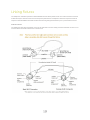
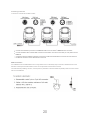
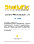
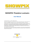
Professional Moving Head User Manual
Version 1.0.0
Table of Contents
Welcome
3
Contacting High End Systems ®
Patents
Warranty Information
Important Safety Information
4
7
9
10
Fixture Overview
11
Features
13
Safety Considerations
14
General Guidelines
15
Installation Instructions
16
Dimensional Drawings
17
Mounting Orientations
18
Linking Fixtures
19
DMX Start Address
21
Fixture Control Board
22
Control Board Functions
24
Preset Programming and Playback
32
DMX Protocol
37
Error Codes
42
ii
Welcome
Notice
© Barco Lighting Systems, 2014, All Rights Reserved Information and specifications in this document are subject to change without
notice. Barco Lighting Systems assumes no responsibility or liability for any errors or inaccuracies that may appear in this manual.
Trademarks used in this text: High End Systems, Wholehog, and Lithopatterns are registered trademarks: and intellaspot, Internal
Effects, the High End Systems globe logo, and the Hog logo are trademarks of Barco Lighting Systems, High End Systems, Inc. is a
registered trademark. Belden is a registered trademark of Belden, Inc. Other trademarks and trade names may be used in this document to refer to either the entities claiming the marks and names or their products. High End Systems disclaims any proprietary
interest in trademarks and trade names owned by others.
3
Contacting High End Systems ®
Sales Department
High End Systems, Inc.
2105 Gracy Farms Lane
Austin, TX 78758 USA
voice:512.836.2242
fax:512.837.5290
Toll Free: 800.890.8989
Customer Service
High End Systems, Inc.
2105 Gracy Farms Lane
Austin, TX 78758 USA
voice:800.890.8989
fax: 512.834.9195
toll free: 800.890.8989
email: [email protected]
World Wide Web
http://www.highend.com
4
5
6
Patents
This High End Systems product is protected by patents and pending patent applications.
Patents owned or licensed by High End Systems include:
US 4,392,187; US 4,602,321; US 4,688,161; US 4,701,833; US 4,709,311; US 4,779,176; US 4,800,474; US 4,962,687;
US 4,972,306; US 4,980,806; US 5,010,459; US 5,031,078; US 5,073,847; US 5,078,039; US 5,186,536; US 5,209,560;
US 5,278,742; US 5,282,121; US 5,307,295; US 5,329,431; US 5,331,822; US 5,367,444; US 5,402,326; US 5,414,328;
US 5,426,576; US 5,430,629; US 5,432,691; US 5,454,477; US 5,455,748; US 5,502,627; US 5,506,762; US 5,515,254;
US 5,537,303; US 5,545,951; US 5,588,021; US 5,590,954; US 5,590,955; US 5,640,061; US 5,647,662; US 5,691,886;
US 5,702,082; US 5,728,994; US 5,758,955; US 5,758,956; US 5,769,527; US 5,769,531; US 5,774,273; US 5,788,365;
US 5,794,881; US 5,795,058; US 5,798,619; US 5,806,951; US 5,812,596; US 5,823,661; US 5,825,548; US 5,828,485;
US 5,829,868; US 5,857,768; US 5,882,107; US 5,921,659; US 5,934,794; US 5,940,204; US 5,945,786; US 5,953,151;
US 5,953,152; US 5,969,485; US 5,980,066; US 5,983,280; US 5,984,248; US 5,986,201; US 6,011,662; US 6,029,122;
US 6,048,080; US 6,048,081; US 6,054,816; US 6,057,958; US 6,062,706; US 6,079,853; US 6,126,288; US 6,142,652;
US 6,142,653; US 6,172,822; US 6,175,771; US 6,188,933; US 6,208,087; US 6,219,093; US 6,220,730; US 6,241,366;
US 6,249,091; US 6,255,787; US 6,256,136; US 6,261,636; US 6,278,542; US 6,278,545; US 6,278,563; US 6,288,828;
US 6,326,741; US 6,327,103; US 6,331,756; US 6,346,783; US 6,421,165; US 6,430,934; US 6,459,217; US 6,466,357;
US 6,502,961; US 6,515,435; US 6,523,353; US 6,536,922; US 6,538,797; US 6,545,586; US 6,549,324; US 6,549,326;
US 6,563,520; US 6,565,941; US 6,570,348; US 6,575,577; US 6,578,991; US 6,588,944; US 6,592,480; US 6,597,132;
US 6,600,270; US 6,601,974; US 6,605,907; US 6,617,792; US 6,621,239; US 6,622,053; US 6,635,999; US 6,648,286;
US 6,664,745; US 6,682,031; US 6,693,392; US 6,696,101; US 6,719,433; US 6,736,528; US 6,771,411; US 6,775,991;
US 6,783,251; US 6,801,353; US 6,812,653; US 6,823,119; US 6,865,008; US 6,866,390; US 6,866,402; US 6,866,451;
US 6,869,193; US 6,891,656; US 6,894,443; US 6,919,916; US 6,930,456; US 6,934,071; US 6,937,338; US 6,955,435;
US 6,969,960; US 6,971,764; US 6,982,529; US 6,988,805; US 6,988,807; US 6,988,817; US 7,000,417; US 7,011,429;
US 7,018,047; US 7,020,370; US 7,033,028; US 7,048,838; US 7,055,963; US 7,055,964; US 7,057,797; US 7,073,910;
US 7,078,869; US 7,092,098; US 7,119,902; US 7,161,562; US 7,175,317; US 7,181,112; US 7,206.023; US 7,210,798;
US 7,253,942; US D347,113; US D350,408; US D359,574; US D360,404; US D365,165; US D366,712; US D370,080;
US D372,550; US D374,439; US D377,338; US D381,740; US D409,771; AT E169413; CA 2142619; CA 2145508;
CA 2245842; DE 22588.4-08; DE 621495; DE 655144; DE 69320175.4; DE 69322401.0; DE 69331145.2; DE 69525856.7;
DE 69734744.3; DE 797503; DK 0655144; DK 1447702; EP 0475082; EP 0621495; EP 0655144; EP 0662275;
EP 0767398; EP 0797503; EP 0969247; EP 1447702; ES 0621495; FR 0621495; FR 0655144; FR 0662275;
FR 1447702; GB 2043769B; GB 2055842B; GB 2283808B; GB 2290134B; GB 2291814B; GB 2292530B;
GB 2292896B; GB 2294909B; GB 2295058B; GB 2303203B; GB 2306887B; GB 2307036B; GB 2316477B; IE 0621495;
IT 034244BE; 2005; IT 0621495; IT 0655144; JP 3495373; JP 3793577; NL 0621495; NL 0797503; NL 0969247;
UK 0621495; UK 0655144; UK 0662275; UK 0797503; UK 0969247; UK 1447702;
7
8
Warranty Information
Limited Warranty
Unless otherwise stated, your product is covered by a one year parts and labor limited warranty. Dichroic filters and LithoPatterns®
high resolution glass gobos are not guaranteed against breakage or scratches to coating. It is the owner’s responsibility to furnish
receipts or invoices for verification of purchase, date, and dealer or distributor. If purchase date cannot be provided, date of manufacture will be used to determine warranty period.
Returning an Item Under Warranty for Repair
It is necessary to obtain a Return Material Authorization (RMA) number from your dealer or point of purchase BEFORE any units are
returned for repair. The manufacturer will make the final determination as to whether or not the unit is covered by warranty.
A fixture must be returned in its original packaging. Any other parts returned to High End Systems must be packaged in a suitable
manner to ensure the protection of such product unit or parts, and such package shall be clearly and prominently marked to indicate
that the package contains returned Product units or parts and with an RMA number. Accompany all returned Product units or parts
with a written explanation of the alleged problem or malfunction. Ship returned Product units or parts to: 2105 Gracy Farms Lane,
Austin, TX 78758 USA.
Note:Freight Damage Claims are invalid for fixtures shipped in non-factory boxes and packing materials.
Freight
All shipping will be paid by the purchaser. Items under warranty shall have return shipping paid by the manufacturer only in the Continental United States. Under no circumstances will freight collect shipments be accepted. Prepaid shipping does not include rush expediting such as air freight. Air freight can be sent customer collect in the Continental United States.
REPAIR OR REPLACEMENT AS PROVIDED FOR UNDER THIS WARRANTY IS THE EXCLUSIVE REMEDY OF THE
CONSUMER. HIGH END SYSTEMS, INC. MAKES NO WARRANTIES, EXPRESS OR IMPLIED, WITH RESPECT TO ANY
PRODUCT, AND HIGH END SPECIFICALLY DISCLAIMS ANY WARRANTY OF MERCHANTABILITY OR FITNESS FOR A
PARTICULAR PURPOSE. HIGH END SHALL NOT BE LIABLE FOR ANY INDIRECT, INCIDENTAL OR CONSEQUENTIAL
DAMAGE, INCLUDING LOST PROFITS, SUSTAINED OR INCURRED IN CONNECTION WITH ANY PRODUCT OR CAUSED
BY PRODUCT DEFECTS OR THE PARTIAL OR TOTAL FAILURE OF ANY PRODUCT REGARDLESS OF THE FORM OF
ACTION, WHETHER IN CONTRACT, TORT (INCLUDING NEGLIGENCE), STRICT LIABILITY OR OTHERWISE, AND
WHETHER OR NOT SUCH DAMAGE WAS FORESEEN OR UNFORESEEN.
Warranty is void if the product is misused, damaged, modified in any way, or for unauthorized repairs or parts. This warranty gives
you specific legal rights, and you may also have other rights which vary from state to state.
9
Important Safety Information
Instructions pertaining to continued protection against fire, electric shock, and injury to persons are found throughout this manual.
Please read all instructions prior to assembling, mounting, and operating this equipment.
The following international caution and warning symbols appear in margins throughout this manual to highlight messages.
10
Fixture Overview
1: Lens
2: Handle
3: Microphone
4: Display
5: Left-button
6: Down-button
7: ENTER-button
8: Right-button
9: Mode/Esc-button
10: Up-button
11: 5-Pin DMX out
12: 5-Pin DMX in
13: 3-Pin DMX in
14: 3-Pin DMX out
15: Power supply
16: Fuse
11
This page intentionally left blank to ensure new
chapters start on right (odd number) pages.
12
Features
•DMX Channels mode: 48 channels
•Stand alone operation with Master/Slave function, sound activated via built in microphone.
•Pan and tilt movement: 8 and 16 bit resolution
For smooth and precise motion
Movement: Pan: 540°/630°optional, Tilt: 265°
Speed of pan/tilt movement adjustable
Scan position memory, auto reposition after unexpected movement
•Colors: Basic color wheel with 6 dichroic mirrors, plus white, two direction rainbow effect.
•CMY & CTO Variable Color Mixing for Infinite Color Possibilities
•Rotation gobo: 6 interchangeable, rotating gobos plus open
•Gobo wheel with 7 interchangeable gobos plus open, gobo shaking in different speed
•Dimmer intensity from 0%~100%
•Prism and prism rotating , with 16 prism macros
•Iris from 5%~100% with pulse iris effect.
•Stepless frost, 0%~100% linear change frost
•Control board with full color LCD graphic display and touch-keyboard
•Display: Can be changed 180° reverse to fit for different installation position.
•Strobe/shutter: High speed shutter, 0-13 Hz or random strobe
•Rechargeable Back up Battery for Display, no need external power supply, enable users to enter display menu for address setting
or access other functions setting.
•Software-upload by optional accessory via DMX line
13
Safety Considerations
This device has left the factory in perfect condition. In order to maintain this condition and to ensure a safe operation, it is absolutely
necessary for the user to follow the safety instructions and warning notes written in this user manual.
Important:
Damages caused by the disregard of this user manual are not subject to warranty. The dealer will not accept liability
for any resulting defects or problems.
l
If the device has been exposed to temperature changes due to environmental changes, do not switch it on immediately. The
condensation could cause damage to the device. Leave the device switched off until it has reached room temperature.
l
This device falls under protection-class I. Therefore it is essential that the device be earthed.
l
The electrical connection must carry out by a qualified person.
l
Make sure that the available voltage is within stated range.
l
l
Make sure the power cord is never crimped or damaged by a sharp edge. Replace cable immediatly if damaged, this work
must be done by an authorized dealer.
Always disconnect from power, when the device is not in use or before cleaning it. Only handle the power cord by the plug.
Never pull out the plug by tugging the power cord.
l
Don't project the beam onto combustible substances, as this causes a safety hazard.
l
Please be aware that damages caused by manual modifications will void warranty.
l
Keep away from children and non-professionals.
l
Maintenance
l
There are no serviceable parts inside the device except for the lamp. The following points have to be considered when
inspecting the fixture for maintenance:
l
All screws for installing the devices or parts of the device have to be tightly connected and must not be corroded.
l
Mechanically moved parts must not show any traces of wearing and must not rotate with unbalances.
l
The electric power supply cables must not show any damage, material fatigue or dirt.
14
General Guidelines
l
l
l
l
l
l
l
This device is a lighting effect for professional use on stages, theaters, or other professional installations, etc., the device was
designed for indoor use only.
This fixture is only allowed to be operated with the max alternating current which stated in the technical specifications printed
on the fixture.
Lighting effects are not designed for permanent operation. Consistent operation breaks may ensure that the device will
serve you for a long time without defects.
Do not shake the device.Avoid brute force when installing or operating the device.
While choosing the installation-spot, please make sure that the device is not exposed to extreme heat, moisture or dust.
Please don't project the beam onto combustible substances.The minimum distance between light-output from the projector
and the illuminated surface must be more than 0.1 meter.
If you use the quick lock cam in hanging up the fixture, please make sure the quick lock fasteners turned in the quick lock
holes correctly.
Operate the device only after having familiarized with its functions. Do not permit operation by persons not qualified for operating the device. Most damages are the result of unprofessional operation.
l
Please use the original packaging if the device is to be transported.
l
For safety reasons, please be aware that all modifications on the device are forbidden.
l
If this device will be operated in any way different to the one described in this manual, the product may suffer damages and
the guarantee becomes void. Furthermore, any other operation may lead to short-circuit, burns, electric shock, lamp explosion, crash, etc.
15
Installation Instructions
l
l
l
l
l
The installation must always be secured with a secondary safety attachment, e.g. an appropriate safety
cable.
Never stand directly below the device when mounting, removing or servicing the fixture.
The operator has to make sure the safety and technical installations are approved by an expert before taking using this fixture in the field for the first time.
These installations must be inspected by a skilled person once a year.
Overhead mounting requires extensive experience, including amongst others calculating working load limits, installation material being used, and periodic safety inspection of all installation material and the device.
If you lack these qualifications, do not attempt the installation yourself. Improper installation can result in
serious bodily injury.
Attachment Instructions.
l
Attach the Omega clamp on the bracket by tighten the M12 bolt on the bracket to the hole in the middle of the bracket.
l
Insert the quick-lock fasteners of the bracket into the respective holes on the bottom of the fixture.
l
Tighten the quick-lock fasteners fully clockwise.
l
Install the second Omega clamp.
l
Attach the safety-cable through the holes on the bottom of the base. Attach to the trussing system or other safe fixation
point.
l
Be sure the safety is fully looped, the quick-link is attached and fully tighten
l
Inspect for complete attachment before lifting over-head
16
Dimensional Drawings
Dims listed in (MM)
17
Mounting Orientations
Be sure this fixture is kept at least 0.5m (1.6ft) away from any flammable materials (decoration etc.). Always use and install the supplied safety cable as a safety measure to prevent accidental damage and/or injury in the event the clamp is improperly installed or
fails.
Overhead mounting requires extensive experience, including amongst others calculating working load limits, a fine knowledge of the
installation material being used, and periodic safety inspection of all installation material and the fixture. If you lack these qualifications,
do not attempt the installation yourself. Improper installation can result in bodily injury.
18
Linking Fixtures
The SolaSpot Pro 1500 fixture operates on standard DMX512 link controlled by a DMX console. The number of fixtures on a link will
be determined by the combined number of channels required by all the fixtures. A SolaSpot Pro CMY fixture requires a 48 channel
footprint on a standard DMX512 link. Attach the fixture to the link using data-grade cable and 5-pin or 3-pin XLR cable connectors
Cable Connectors
The SolaSpot Pro CMY fixture accepts both 3-pin and 5-pin XLR cable connectors. Cabling must have a male XLR connector on one
end of the cable and a female XLR connector on the other end.
19
Connecting to the Link
To link one or more fixtures to a DMX controller:
l
l
l
Connect the male XLR connector of a DMX Data cable to the controller’s DMX Data Out connector.
Connect the Data cable’s female XLR connector to the Data In connector of the first (or next) fixture on the
DMX link.
Continue linking the remaining fixtures connecting a cable from the Data Out connector of each fixture to
the Data In connector of the next fixture on the link.
DMX Terminatation
For installations where the DMX cable has to run a long distance or is in an electrically noisy environment, a DMX terminator on the
last fixture of the link prevents data reflection, which cancorrupt the data communication on the link.
Terminate the link by installing a 120 ohm, 1/4 watt (minimum) terminator in the fixture’s Data Out (female) cable connector in the last
fixture on each DMX link.
20
DMX Start Address
All fixtures should be given a unique DMX starting address when using a DMX signal, so that the correct fixture responds to the correct control signals. This DMX start address is the channel number from which the fixture starts to “listen” to the digital control information sent out from the DMX controller. The setting of this start address is achieved by setting the correct number on the display
located on the base of the device.
You can set the same starting address for all fixtures or a group of fixtures, or make use different addresses for each fixture individually.
If you set the same address, all the units will start to “listen” to the same control signal from the same channel number. In other words,
changing the settings of one channel will affect all the fixtures simultaneously.
If you set a different address, each unit will start to “listen” to the channel number you have set, based on the quantity of control channels of the unit. That means changing the settings of one channel will affect only the selected fixture.
In the case of the moving head, which is a 48 channel fixture, you should set the starting address of the first unit to 1, the second unit
to 49 (48+ 1), the third to 97(48+ 49), and so on.
21
Fixture Control Board
The Control Board offers several features: you can simply set the starting address , run the pre-programmed program or make a
reset.
The main menu is accessed by pressing the [Mode / ESC] button until the display starts flashing. Browse through the menu by pressing the [UP] button ,[Down] button , [Left] button or [Right] button. Press the [Enter] button in order to select the desired menu.
You can change the selection by pressing the directional buttons. ie. the [UP] button ,[Down] button , [Left] button or [Right]
Confirm every selection by pressing the [Enter].
You can leave every mode or access the display menu via the internal battery by pressing the [Mode / Esc ]button for 15 sec;
The functions provided are described in the following sections. it will exit from flash 10 seconds after the last keypress. Press this key
under edit mode, . The functions provided are described in the following sections.
22
23
Control Board Functions
Address
With this function, you can adjust the desired DMX-address via the Control Board.
1.Access the main menu.
2.Tap the <Up/Down>button until“Address”is displayed.
3.Press ENTER, the display will show “Address”.
4.Tap the <Up/Down>button,the display will show “A001~AXXX”
5.Press ENTER to confirm or press <MODE/ESC> to return to the main menu
Time Info
Current Time
With this function, you can display the temporary running time of the device from the last power on. The display shows “XXXX”,
“XXXX” stands for the number of hours. The counter is resetted after turning the device off.
1.Tap <MODE/ESC>button,access the main menu,Tap the <Up/Down>button until“Info”is displayed. Press ENTER, the display
will show “Info.”. Tap the <Up/Down>button until the display will show “Time Info.”. Press ENTER, the display will show “Time Info.”.
2.Press <Up/Down>, the display will show “Current Time”.
3.Press< ENTER>, the display will show “Current Time”.
4.The display will show “XXXX” (Hours) ;
5.Press <ENTER> to confirm or press <MODE/ESC> to return to the main menu.
Ttl Life Hrs
With this function, you can display the running time of the device. The display shows “XXXX”, “XXXX” stands for the number of hours.
1.Tap <MODE/ESC>button,access the main menu,Tap the <Up/Down>button until“Info”is displayed. Press ENTER, the display
will show “Info.”. Tap the <Up/Down>button until the display will show “Time Info.”. Press ENTER, the display will show “Time Info.”.
2.Press <Up/Down>, the display will show “Ttl Life Hrs”.
3.Press< ENTER>, the display will show “Ttl Life Hrs”.
4.The display will show “XXXX” (Hours) ;
5.Press <ENTER> to confirm or press <MODE/ESC> to return to the main menu.
Last Run Hrs
With this function, you can display last the running time of the lamp. The display shows “XXXX”, “XXXX” stands for the number of
hours.
1.Tap <MODE/ESC>button,access the main menu,Tap the <Up/Down>button until“Info”is displayed. Press ENTER, the display
will show “Info”. Tap the <Up/Down>button until the display will show “Time Info.”. Press ENTER, the display will show “Time Info.”.
2.Press <Up/Down>, the display will show “Last Run Hrs”.
3.Press< ENTER>, the display will show “Last Run Hrs”.
4.The display will show “XXXX” (Hours) ;
5.Press <ENTER> to confirm or press <MODE/ESC> to return to the main menu.
24
Timer PIN
With this function, you can display the timer password. The time password is 038.
1.Tap <MODE/ESC>button,access the main menu,Tap the <Up/Down>button until“Info”is displayed. Press ENTER, the display
will show “Info”. Tap the <Up/Down>button until the display will show “Time Info.”. Press ENTER, the display will show “Time Info.”.
2.Press <Up/Down>, the display will show “Timer PIN”.
3.Press< ENTER>, the display will show “Timer PIN”, the time password is 038.
4.Press <ENTER> to confirm or press <MODE/ESC> to return to the main menu.
Clr Last Run
With this function, you can clear last run time of the fixture. The display shows “OFF” or “ON”, Press “Enter” to confirm.
1.Tap <MODE/ESC>button,access the main menu,Tap the <Up/Down>button until“Info”is displayed. Press ENTER, the display
will show “Info”. Tap the <Up/Down>button until the display will show “Time Info.”. Press ENTER, the display will show “Time Info.”.
2.Press <Up/Down>, the display will show “Clr Last Run”.
3.At“Timer Password”menu input a correct password, press< ENTER>, the display will show “Clr Last Run”,
4.The display will show “OFF”or“ON”.
5.Press <ENTER> to confirm or press <MODE/ESC> to return to the main menu.
Value Displayed
NONE
With this function, you can choose DMX Control.
1.Tap <MODE/ESC>button,access the main menu,Tap the <Up/Down>button until“Info”is displayed. Press ENTER, the display
will show “Info”.
2.Press <Up/Down>, the display will show “Value Disp”.
3.Press< ENTER>, the display will show “Value Disp”.
4.The display show “None”.
5.Press <ENTER> to confirm or press <MODE/ESC> to return to the main menu.
ALL, PAN
With this function you can display the DMX 512 value of each channel. The display automatically shows the channel with a value changing.
1.Tap <MODE/ESC>button,access the main menu,Tap the <Up/Down>button until“Info”is displayed. Press ENTER, the display
will show “Info”.
2.Tap the <Up/Down>button until“Value Disp”is displayed.
3.Press ENTER, the display will show “Value Disp”.
4.Tap the <Up/Down>button,choose each channel.
5.Press ENTER to confirm or press <MODE/ESC> to return to the main menu.
Head Temp.
With this function you can display the temperature on the display board of the base (near CMY-filter) in Celsius.
1.Tap <MODE/ESC>button,access the main menu,Tap the <Up/Down>button until“Info”is displayed. Press ENTER, the display
will show “Info”.
2.Press <Up/Down>, the display will show “Head Temp.”.
25
3.Press< ENTER>, the display will show “Head Temp.”.
4.The display show “XXX °C/ °F”.
5.Press <ENTER> to confirm or press <MODE/ESC> to return to the main menu.
Software Ver
With this function, you can display the software version of the device.
1.Tap <MODE/ESC>button,access the main menu,Tap the <Up/Down>button until“Info”is displayed. Press ENTER, the display
will show “Info”.
2.Press <Up/Down>, the display will show “Software Ver”.
3.Press< ENTER>, the display will show “Software Ver”.
4.The display show “Ver x.x”.
5.Press <ENTER> to confirm or press <MODE/ESC> to return to the main menu.
Set
Status
No DMX Mode
With this function, when the drive is not DMX signal, it runs automatism, close, hold and music, the default is hold.
1.Tap <MODE/ESC>button,access the main menu,Tap the <Up/Down>button until“Set”is displayed. Press ENTER, the display
will show“Set”. Tap the <Up/Down>button until the display will show “Status”. Press ENTER, the display will show “Status”.
2.Press <Up/Down>, the display will show “No DMX Mode”.
3.Press< ENTER>, the display will show “No DMX Mode”.
4.The display show “Hold”,Press <Up/Down>, the display will show “Close”, “Auto”, “Music”.
5.Press <ENTER> to confirm or press <MODE/ESC> to return to the main menu.
Pan Reverse
With this function you can reverse the Pan-movement.
1.Tap <MODE/ESC>button,access the main menu,Tap the <Up/Down>button until“Set”is displayed. Press ENTER, the display
will show“Set”. Tap the <Up/Down>button until the display will show “Status”. Press ENTER, the display will show “Status”.
2.Press <Up/Down>, the display will show “Pan Reverse”.
3.Press< ENTER>, the display will show “Pan Reverse”.
4.The display show “OFF”,Press <Up/Down>, the display will show “ON”.
5.Press <ENTER> to confirm or press <MODE/ESC> to return to the main menu.
Tilt Reverse
With this function you can reverse the Tilt-movement.
1.Tap <MODE/ESC>button,access the main menu,Tap the <Up/Down>button until“Set”is displayed. Press ENTER, the display
will show“Set”. Tap the <Up/Down>button until the display will show “Status”. Press ENTER, the display will show “Status”.
2.Press <Up/Down>, the display will show “Tilt Reverse”.
3.Press< ENTER>, the display will show “Tilt Reverse”.
4.The display show “OFF”,Press <Up/Down>, the display will show “ON”.
5.Press <ENTER> to confirm or press <MODE/ESC> to return to the main menu.
Pan Degree
26
With this function, you can select pan degree for 630 or 540.
1.Tap <MODE/ESC>button,access the main menu,Tap the <Up/Down>button until“Set”is displayed. Press ENTER, the display
will show“Set”. Tap the <Up/Down>button until the display will show “Status”. Press ENTER, the display will show “Status”.
2.Press <Up/Down>, the display will show “Pan Degree”.
3.Press< ENTER>, the display will show “Pan Degree”.
4.The display show “540”,Press <Up/Down>, the display will show “630”.
5.Press <ENTER> to confirm or press <MODE/ESC> to return to the main menu.
Encoders
With this function, you can feedback switch of pan movement or tilt movement.
1.Tap <MODE/ESC>button,access the main menu,Tap the <Up/Down>button until“Set”is displayed. Press ENTER, the display
will show“Set”. Tap the <Up/Down>button until the display will show “Status”. Press ENTER, the display will show “Status”.
2.Press <Up/Down>, the display will show “Encoders”.
3.Press< ENTER>, the display will show “Encoders”.
4.The display show “ON”,Press <Up/Down>, the display will show “OFF”.
5.Press <ENTER> to confirm or press <MODE/ESC> to return to the main menu.
Pan/Tilt Spd
With this function, you can select scan mode from 1 to 4.
1.Tap <MODE/ESC>button,access the main menu,Tap the <Up/Down>button until“Set”is displayed. Press ENTER, the display
will show“Set”. Tap the <Up/Down>button until the display will show “Status”. Press ENTER, the display will show “Status”.
2.Press <Up/Down>, the display will show “Pan/Tilt Spd”.
3.Press< ENTER>, the display will show “Pan/Tilt Spd”.
4.The display show “Speed 1”,Press <Up/Down>, the display will show “Speed 2”, “Speed 3”, “Speed 4”.
5.Press <ENTER> to confirm or press <MODE/ESC> to return to the main menu.
Mic Sens.
With this function, the default is 70%, you can select the desired microphone sensitivity from 0 % to 99 %.
1.Tap <MODE/ESC>button,access the main menu,Tap the <Up/Down>button until“Set”is displayed. Press ENTER, the display
will show“Set”. Tap the <Up/Down>button until the display will show “Status”. Press ENTER, the display will show “Status”.
2.Press <Up/Down>, the display will show “Mic Sens.”.
3.Press< ENTER>, the display will show “Mic Sens.”.
4.The display show “70%”,Press <Up/Down>, the display will show “0~99%”.
5.Press <ENTER> to confirm or press <MODE/ESC> to return to the main menu.
Hibernation ——Standby mode
The lamp and step motors will be power off if the fixture stay without DMX signal for 15 mins (Factory default).And the fixture will be
reset before working once it receive DMX signal again.
1.Tap <MODE/ESC>button,access the main menu,Tap the <Up/Down>button until“Set”is displayed. Press ENTER, the display
will show“Set”. Tap the <Up/Down>button until the display will show “Status”. Press ENTER, the display will show “Status”.
2.Press <Up/Down>, the display will show “Hibernation”.
3.Press< ENTER>, the display will show “Hibernation”.
27
4.The display show “15M”,Press <Up/Down>, the display will show “01M”,“02M” …. “99M” or“OFF”.
5.Press <ENTER> to confirm or press <MODE/ESC> to return to the main menu.
Service PIN
Service PIN——The Password for this function is “50”.
RDM PID—— With this function you can call up various submenus via RDM.
This device is RDM ready. RDM stands for "remote device management" and makes remote control of devices connected to the
DMX-bus. ANSI E1.20-2006 by ESTA specifies the RDM standard as an extension of the DMX512 protocol.
Manual settings like adjusting the DMX starting address are no longer needed. This is especially useful when the device is installed in
a remote area.
RDM ready and conventional DMX devices can be operated in one DMX line. The RDM protocol sends own packages in the
DMX512 data feed and does not influence conventional devices.
If DMX splitters are used and RDM control is to be used, these splitters must support RDM.
The number and type of RDM parameters depend on the RDM controller being used.
Disp.Setting
Shutoff Time
With this function you can shut off the color LCD display after 2 to 60 minutes. Turn the encoder in order to select the desired shut off
time. The default is 2 minute.
Flip Display
With this function you can rotate the display by 180°.
1.Tap <MODE/ESC>button,access the main menu,Tap the <Up/Down>button until“Set”is displayed. Press ENTER, the display
will show “Set”. Tap the <Up/Down>button until the display will show “Disp.Setting”. Press ENTER, the display will show “Disp.Setting”.
2.Press <Up/Down>, the display will show “Flip Display”.
3.Press< ENTER>, the display will show “Flip Display”.
4.The display show “OFF”,Press <Up/Down>, the display will show “ON”.
5.Press <ENTER> to confirm or press <MODE/ESC> to return to the main menu.
Key Lock
With this function you can activate the automatic keylock status. If this function is activated, the keys will be locked automatically after
exiting the edit mode for 15 seconds. keeping press the<MODE/ESC> key for 3seconds if you do not need this function.
1.Tap <MODE/ESC>button,access the main menu,Tap the <Up/Down>button until“Set”is displayed. Press ENTER, the display
will show “Set”. Tap the <Up/Down>button until the display will show “Disp.Setting”. Press ENTER, the display will show “Disp.Setting”.
2.Press <Up/Down>, the display will show“Key Lock”.
3.Press< ENTER>, the display will show“Key Lock”.
4.The display show “ON”,Press <Up/Down>, the display will show “OFF”.
5.Press <ENTER> to confirm or press <MODE/ESC> to return to the main menu.
28
Temp. C/F
With this function, Display the temperature for Celsius or Fahrenheit.
1.Tap <MODE/ESC>button,access the main menu,Tap the <Up/Down>button until“Set”is displayed. Press ENTER, the display
will show “Set”.
2.Press <Up/Down>, the display will show“Temp. C/F”.
3.Press< ENTER>, the display will show“Temp. C/F”.
4.The display show “Celsius”,Press <Up/Down>, the display will show “Fahrenheit”.
5.Press <ENTER> to confirm or press <MODE/ESC> to return to the main menu.
ResetDefault
With this function, you can select restore factory set for ON or OFF, the default is OFF.
1.Tap <MODE/ESC>button,access the main menu,Tap the <Up/Down>button until“Set”is displayed. Press ENTER, the display
will show “Set”.
2.Press <Up/Down>, the display will show“ResetDefault”.
3.Press< ENTER>, the display will show“ResetDefault”.
4.The display show “OFF”,Press <Up/Down>, the display will show “ON”.
5.Press <ENTER> to confirm or press <MODE/ESC> to return to the main menu.
Test
Home
With this function you can reset the device via the Control Board. You can select the different reset functions by turning the encoder.
1.Tap <MODE/ESC>button,access the main menu,Tap the <Up/Down>button until“Test”is displayed. Press ENTER, the display
will show “Test”. Tap the <Up/Down>button until the display will show “Home”. Press ENTER, the display will show “Home”.
2.The display show “ All”, Press <Up/Down>, the display will show “Pan&Tilt”,“Colors”, “Shutter”, “Others”.
3.Press <ENTER> to confirm or press <MODE/ESC> to return to the main menu.
Test Channel
With this function you can test each channel on its (correct) function.
1.Tap <MODE/ESC>button,access the main menu,Tap the <Up/Down>button until“Test”is displayed. Press ENTER, the display
will show “Test”.
2.Press <Up/Down>, the display will show “Test Channel”.
3.Press< ENTER>, the display will show “Test Channel”.
4.The display show “Pan Moving”frist channel, Press <Up/Down>, can choose other channel.
5.Press <ENTER> to confirm or press <MODE/ESC> to return to the main menu.
Manual Ctrl.
With this function, you can adjust the lamp more easily. All effects will be canceled, the shutter opens and the dimmer intensity will be
set to 100 %. With the individual functions, you can focus the light on a flat surface (wall) and erform the fine lamp adjustment.
1.Tap <MODE/ESC>button,access the main menu,Tap the <Up/Down>button until“Test”is displayed. Press ENTER, the display
will show “Test”.
2.Press <Up/Down>, the display will show “Manual Ctrl.”.
3.Press< ENTER>, the display will show “Manual Ctrl.”.
29
4.The display show “PAN=XXX”.
5.Press <ENTER> to confirm or press <MODE/ESC> to return to the main menu.
Calibration
With this function, you can calibrate and adjust the effect wheels to their correct positions. The password of calibrate values is 050.
1.Tap <MODE/ESC>button,access the main menu,Tap the <Up/Down>button until“Test”is displayed. Press ENTER, the display
will show “Test”.
2.Press <Up/Down>, the display will show “Calibration”.
3.Press< ENTER>, the display will show “Calibration”.
4.The display show “Password=XXXX”.
5.Press <ENTER> to confirm or press <MODE/ESC> to return to the main menu.
Preset
In this menu, user can select different channels list by different sequence:
For example, after the user enter this manual, if select Auto Program = CH 22, means in this User’s mode, the “Dimmer” is in Channel 16.
PlayBack
DMX Control
With this function you can display the DMX 512 value of each channel. The display automatically shows the channel with a value changing.
1.Tap <MODE/ESC>button,access the main menu,Tap the <Up/Down>button until“Preset”is displayed. Press ENTER, the display will show “Preset”. Tap the <Up/Down>button until the display will show “PlayBack”. Press ENTER, the display will show
“PlayBack”.
2.Tap the <Up/Down>button until“DMX Control”is displayed.
3.Press ENTER, the display will show “DMX Control”.
4.Tap the <Up/Down>button,choose each channel.
5.Press ENTER to confirm or press <MODE/ESC> to return to the main menu.
Set To Slave
With this function, you can define the device as slave.
1.Tap <MODE/ESC>button,access the main menu,Tap the <Up/Down>button until“Preset”is displayed. Press ENTER, the display will show “Preset”. Tap the <Up/Down>button until the display will show “PlayBack”. Press ENTER, the display will show
“PlayBack”.
2.Tap the <Up/Down>button until“Set To Slave”is displayed.
3.Press ENTER, the display will show “Set To Slave”.
4.Tap the <Up/Down>button,the display will show “Slave1”, ”Slave2”, ”Slave3”.
5.Press ENTER to confirm or press <MODE/ESC> to return to the main menu.
Auto Program
With this function, you can run the internal program. You can select the desired program under “Select program”. You can set the
number of steps under “Edit program”. You can edit the individual scenes under “Edit scenes”. With this function, you can run the individual scenes either automatically, i.e. with the adjusted Step-Time.
30
1.Tap <MODE/ESC>button,access the main menu,Tap the <Up/Down>button until“Preset”is displayed. Press ENTER, the display will show “Preset”. Tap the <Up/Down>button until the display will show “PlayBack”. Press ENTER, the display will show
“PlayBack”.
2.Tap the <Up/Down>button until“Auto Program”is displayed.
3.Press ENTER, the display will show “Auto Program”.
4.Tap the <Up/Down>button,the display will show “Master1”, ” Alone”.
5.Press ENTER to confirm or press <MODE/ESC> to return to the main menu.
Music Ctrl.
With this function, you can run the internal program sound-controlled.
1.Tap <MODE/ESC>button,access the main menu,Tap the <Up/Down>button until“Preset”is displayed. Press ENTER, the display will show “Preset”. Tap the <Up/Down>button until the display will show “PlayBack”. Press ENTER, the display will show
“PlayBack”.
2.Tap the <Up/Down>button until“Music Ctrl.”is displayed.
3.Press <ENTER>, the display will show “Music Ctrl.”.
4.Tap the <Up/Down>button,the display will show “Master”, ” Alone”.
5.Press <ENTER> to confirm or press <MODE/ESC> to return to the main menu.
Select Prog.
With this function, you can select the program for the Program Run.
Edit Prog.
With this function, you can edit the internal programs.
Edit Scenes
With this function, you can edit the scenes of the internal programs.
Scenes Input
The moving head features an integrated DMX-recorder by which you can transmit the programmed scenes from your DMX-controller to the moving head. Adjust the desired scene numbers via the encoder (from – to). When you call up the scenes at your controller, they will automatically be transmitted to the moving head.
Battery
With this function, you can exit battery.
31
Preset Programming and Playback
SolaSpot Pro 1500 fixtures can be programmed through the on board menu system using Preset Programming.
This section describes how to program your fixtures for stand-alone operation using the on-board memory in each
fixture to create and store scenes.
Preset Programming Overview
Presets are built from combining scenes into programs and then assigning the programs to Program Partitions for
playback by a fixture designated as the Master and, if desired, groups of slave fixtures assigned to a Program Partition. SolaSpot Pro CMY fixtures ship with factory programmed scenes and programs ready for you to use or edit.
Creating presets consists of performing the following steps:
l
Designating a fixture as the Master
l
Selecting/Editing Scenes
l
Sequencing Scenes into Programs
l
Sequencing Programs into Program Partitions
l
Configuring slave fixtures on the link to playback a Program Partition from the master
Navigating to the Preset Menu
To enter the Preset Menu:
l
Press the [MODE/ESC] button to enter the first level of the menu system. The display will show Address and Info as the first
two options in the top menu level.
l
The red star [*] indicates the current menu.
l
Using the [UP],[DOWN] buttons, scroll to Preset.
l
Press the [Enter] button to select.
Master and Slave
The following example shows the relationship between scenes, programs and partitions
programmed on the Master and how slave groups are assigned.
l
Groups of scenes are edited into Programs 1– 6 on the fixture designated as Master
l
Program 2 is assigned to Part 1
l
Program 4 is assigned to Part 2
l
Program 6 is assigned to Part 3
l
Fixtures assigned as Slave 1 playback Part 1
l
Fixtures assigned as Slave 2 playback Part 2
l
Fixtures assigned as Slave 3 playback Part 3
l
Scene 4 Scene 5 Scene 6 Scene 7
32
Preset Menu
Playback Settings
Preset programming requires one fixture to act as the Master. All other SolaSpot Pro 1500 fixtures on the link can
then be set as laves to playback the Master presets. Slave fixtures receive all their preset parameter and timing
information from the master fixture. Playback settings designate a fixture as a master or a slave and also allow you
to revert from Auto Programming to DMX control from console or set a fixture in Master or standalone mode for
audio control.
Automatic Program Run
This Playback option lets you designate a fixture to playback in Standalone mode or as a Master. Alone is the default setting.
To designate a fixture as a Master:
l
Navigate to and select the Preset menu.
l
Use the[UP],[DOWN] buttons to scroll to Playback menu and press [Enter]to select.
33
l
Use the[UP],[DOWN] buttons to scroll to Auto Program menu and press [Enter]to select.
l
Use the [UP],[DOWN]buttons to scroll to Master and press [Enter]to select. Your choice will be shown in the display.
Set to Slave
After a preset program is defined on a Master fixture, other SolaSpot Pro CMY fixtures on the same DMX link can be designated
laves to playback Program Part 1, 2 or 3 as defined on the Master fixture.
To designate a fixture as a Slave:
l
Navigate to and select the Preset menu.
l
Use the [UP],[DOWN]buttons to scroll to Playback menu and press [Enter]to select.
l
Use the [UP],[DOWN]buttons to scroll to Set To Slave menu and press [Enter]to select.
l
Use the [UP],[DOWN]buttons to scroll to Slave1, Slave2, or Slave3 option and press [Enter]to select.
l
Your choice will be shown in the display.
DMX Control
Selecting this option reverts the function from Auto Program (Preset Programming) to DMX Receive (console control). Selecting
this option will take you back to the menu startup screen where DMX Receive will be displayed as the currently selected function.
Music Control
This Playback option lets you designate a fixture to playback scenes based on audio triggers detected by the internal microphone in
stand alone or as a Master. Alone is the default setting.
Edit Scenes
A parameter is a fixture attribute that can be controlled to modify the light beam in terms of color, beam quality and pattern, intensity,
or focus (position). DMX programming assigns a DMX value to each of the fixture’s parameters. A scene is one combination of parameter settings.
SolaSpot Pro 1500 fixtures provide 250 pre-programmed scenes you can use or edit to build a preset program. The first 64 scenes
ave factory created settings which can be edited as desired.
Edit Scene Parameters
The Edit Scenes option lets you select a DMX value for any of the 35 parameters in the SolaSpot Pro 1500 DMX protocol.
To edit the DMX parameters in a scene:
l
Navigate to and select the Preset menu as shown on page 35.
l
Use the [UP],[DOWN]buttons to scroll to the Edit Scenes option and press [Enter]to select.
l
Use the [UP],[DOWN]buttons to scroll to the Scene number you wish to build on from 1-250 and press to [Enter]select.
l
Use the [UP],[DOWN]buttons to scroll to the parameter you wish to edit (Pan, Tilt, MSpeed, Color Wheel, etc.) and press to
[Enter]select.
Use the [UP],[DOWN]buttons to scroll to a new DMX value for the parameter you have selected and press[Enter] to select. This
takes you back to parameter options. Continue through all parameters until your desired look is complete.
l
When you are finished selecting all parameter values for a particular Scene, press the [MODE/ESC]button to return to the
Preset level menu.
34
Edit Scene Time
This Scene Edit option lets you set the scene time in seconds from 00.2s–99.9s. The default value is 00.3s. This values determines
how long the scene will play before the next scene is triggered.
Set Fade Time
This Scene Edit option lets you set a fade time value from 000–255. This values determines the crossfade time applied to parameters
once the scene is triggered.
Set Input by Out
This Scene Edit option allows you to capture the parameter values for a scene from DMX input into the fixture. Once you create a look
from a DMX console do the following:
l
Navigate to and select the Preset menu as shown on page 35.
l
Use the [UP],[DOWN]buttons to scroll to the Edit Scenes option and press [Enter]to select.
l
Use the [UP],[DOWN]buttons to scroll to the Scene number you wish to build on from 1-250 and press to [Enter]select.
l
Use the [UP],[DOWN]button to scroll to the Input by Out and [Enter]press to select.
l
The scene will record the current parameter values being input via DMX.
l
When you are finished capturing DMX into a scene, press [Enter]to return to the main menu.
Edit Program
This preset menu option lets you select from 10 factory set programs to edit. You can set up to 64 Scenes in a sequence of Steps for
each program. You can also test the program at any time by selecting Program Test to playback the program as it is currently
defined.
To edit a program:
l
Navigate to and select the Preset menu.
l
Use the [UP],[DOWN] buttons to scroll to Edit Prog. menu and press [Enter]to select.
l
Use the [UP],[DOWN] buttons to scroll to a program from Program 1–Program 10 and press [Enter]to select.
l
Use the [UP],[DOWN]buttons to scroll to the Step in the program you want to edit from Step 1 to Step 64 and press [Enter]
to select. The display will show which scene is currently assigned to that step.
l
Use the [UP],[DOWN]buttons to scroll to the scroll to the scene you want to assign to the step and press [Enter]to select.
l
When you have assigned all the steps you want, select End and press [Enter]to save the program.
Select Program
This preset option lets you assign a Preset Program to one of three Program Partitions. A fixture assigned as a Slave can playback
any Program Partition defined by the Master fixture.
Note: The Master fixture can only playback Program Partition 1
To assign a program to each Program Partition:
l
l
l
l
Navigate to and select the Preset menu as shown on page 35.
Use the [UP],[DOWN]buttons to scroll to Select Prog menu and press [Enter]to select. Each Program Part, has 10 preset
programs.
Use the [UP],[DOWN]buttons to scroll to Prog. Part 1 and press [Enter]to select.
Use the [UP],[DOWN]buttons to scroll to a program from Program 1–Program 10 and press [Enter]to select the program
you want to include in the Program Part.
35
l
l
l
l
l
Use the [UP],[DOWN]buttons to scroll to Prog. Part 2 and press [Enter]to select.
Use the [UP],[DOWN]buttons to scroll to a program from Program 1–Program 10 and press[Enter] to select the program
you want to include in the Program Part.
Use the [UP],[DOWN]buttons to scroll to Prog. Part 3 and press [Enter]to select.
Use the [UP],[DOWN]buttons to scroll to a program from Program 1–Program 10 and press [Enter]to select the program
you want to include in the Program Part.
Press the [Mode / ESC] button to return to the main menu.
Scenes Input
This function allows you to capture multiple scenes from DMX values input to the fixture. You first
define the number of scenes to capture and then each time a DMX value changes, a different
scene will be captured.
1. Navigate to and select the Preset menu as shown on page 49.
2.Use the buttons to scroll to the Scenes Input option and press to select.
3.Use the buttons to set the starting scene number.
4.Use the buttons to set the ending scene number. With each change of any DMX value, the capturing scene will advance to the next
one in the range.
5.When all scenes have been recorded, the scenes input menu will automatically exit.
Note: During Scenes Input recording, the SolaSpot Pro CMY does not playback the DMX input, it only captures it. You must edit or
playback the scenes after recording to see the results. It is best to prepare the scenes on a DMX controller with a zero crossfade for
all parameters between each step. Remember any change of a DMX value will advance to the next scene to capture.
36
DMX Protocol
Channel Name
Description
Decimal
Low
Decimal
High
Percent
Low
Percent
High
1
Pan
Pan Coarse
0
255
0%
100%
2
Pan
Pan Fine
0
255
0%
100%
3
Tilt
Tilt Coarse
0
255
0%
100%
4
Tilt
Tilt Fine
0
255
0%
100%
Pure Mix
0
31
0%
12%
Color Mix
Cycle
32
47
13%
18%
Function
Random
48
63
19%
25%
Reserved
64
255
25%
100%
5
Pure Mix
6
Cyan
Full Saturation
0
100%
7
Magenta
Open
255
0%
Yellow
Cycle & Random Modes. Scan Speed
controlled by Cyan Channel
Slow Rate
0
0%
Fast Rate
255
100%
Full Saturation
0
0%
Open (White)
255
100%
8
9
CTO
Full Speed Control
10
Indexed
0
15
0%
6%
Forward Spin
16
31
6%
12%
Static Color
Reverse Spin
32
47
13%
18%
Function
Continuous
48
63
19%
25%
Fast Scan
64
79
25%
31%
Random
80
95
31%
37%
Reserved
96
255
38%
100%
1. Open (White)
0
16
0%
6%
2. (Open/Color 1)
17
32
7%
13%
3. (Color 1)
33
48
13%
19%
4. (Color 1/Color 2)
49
64
19%
25%
5. (Color 2)
65
80
25%
31%
6. (Color 2/Color 3)
81
96
32%
38%
7. (Color 3)
97
112
38%
44%
"Indexed, Scan modes"
11
8. (Color 3/Color 4)
113
128
44%
50%
Static Color
9. (Color 4)
129
144
51%
56%
Position
10. (Color 4/Color 5)
145
160
57%
63%
11. (Color 5)
161
176
63%
69%
12. (Color 5/Color 6)
177
192
69%
75%
13. (Color 6)
193
208
76%
82%
14. (Color 6/Open)
209
224
82%
88%
1. Open (White)
225
255
88%
100%
Spin & Random modes
Stop
0
0%
0%
Slowest to fastest
255
100%
0%
37
Continuous mode
Positioning from 0-360 degrees
0
255
0%
100%
Indexed
0
15
0%
6%
Full Speed Control
12
Forward Wheel Spin
16
31
6%
12%
Gobo 1
Reverse Wheel Spin
32
47
13%
18%
Function
Scan
48
63
19%
25%
Random
64
79
25%
31%
TBD/Indexed
80
255
31%
100%
1. (Open)
0
31
0%
12%
2. (Rot. Gobo 1)
32
63
13%
25%
3. (Rot. Gobo 2)
34
35
13%
14%
4. (Rot. Gobo 3)
96
127
38%
50%
Gobo 1
5. (Rot. Gobo 4)
128
159
50%
62%
Position
6. (Rot. Gobo 5)
160
191
63%
75%
7. (Rot. Gobo 6)
192
223
75%
87%
1. (Open)
224
255
88%
100%
Rotate Stop
0
3
0%
1%
Slowest to fastest
4
255
2%
100%
"Indexed, Scan & Blink modes"
13
Spin & Random modes
Full Speed Control
14
Indexed
0
15
0%
6%
Gobo 1
Forward Rotate
16
31
6%
12%
Rotate
Reverse Rotate
32
47
13%
18%
Function
Forward Strobe Rotate (Gobo animate)
48
63
19%
25%
Reverse Strobe Rotate (Gobo animate)
64
79
25%
31%
Reserved
80
255
31%
100%
0
255
0%
100%
Indexed/Blink Modes
15
16
Gobo 1
Position 0-360 degrees
Rotate
Forward/Reverse/Forward Strobe/Reverse Strobe Rotate Modes
Coarse
Rotate Stop
0
3
0%
1%
Rotate Slowest to Fastest
4
255
2%
100%
0
255
0%
100%
Indexed
0
15
0%
6%
Forward Wheel Spin
16
31
6%
12%
Gobo 2
Reverse Wheel Spin
32
47
13%
18%
Function
Scan
48
63
19%
25%
Random
64
79
25%
31%
TBD/Indexed
80
255
31%
100%
1. (Open)
0
15
0%
6%
2. (Gobo 1)
16
47
6%
18%
3. (Gobo 2)
48
79
19%
31%
Gobo 2
4. (Gobo 3)
80
111
31%
44%
Position
5. (Gobo 4)
112
143
44%
56%
6. (Gobo 5)
144
175
56%
69%
Gobo 1
Indexed Mode
Rotate Fine
Low Order Byte 0-360 degrees
Full Speed Control
17
18
38
7. (Gobo 6)
176
207
69%
81%
8. (Gobo 7)
208
239
82%
94%
1. (Open)
240
255
94%
100%
0
255
0%
100%
Blade Angle Negative
0
127
0%
50%
Blade Angle 0 degrees
128
Blade Angle positive
129
255
51%
100%
0
255
0%
100%
Blade Angle Negative
0
127
0%
50%
Blade Angle 0 degrees
128
Blade Angle positive
129
255
51%
100%
0
255
0%
100%
Blade Angle Negative
0
127
0%
50%
Blade Angle 0 degrees
128
Blade Angle positive
129
255
51%
100%
19
Blade 1 Position Full in (0) to Full out (255) or open
20
Blade 1 Angle
21
Blade 2 Position Full in (0) to Full out (255) or open
22
23
24
25
26
27
28
29
Blade 2 Angle
Blade 3 Position Full in (0) to Full out (255) or open
Blade 3 Angle
Blade 4 Position Full in (0) to Full out (255) or open
Blade 4 Angle
50%
50%
50%
0
255
0%
100%
Blade Angle Negative
0
127
0%
50%
Blade Angle 0 degrees
128
Blade Angle positive
129
255
51%
100%
Frame Angle Negative
0
127
0%
50%
50%
Frame Rotation Frame Angle 0 degrees
128
Coarse
Frame Angle positive
129
255
50%
51%
100%
Frame Angle Negative
0
127
0%
50%
Frame Rotation Frame Angle 0 degrees
128
50%
Fine
Frame Angle positive
129
255
51%
100%
Animation
Close
0
7
0%
3%
Function
Animation speed from fast to slow
8
255
3%
100%
Disengaged
0
15
0%
6%
Continuous
16
31
6%
12%
Prism
Forward Spin
32
47
13%
18%
Function
Reverse Spin
Full Speed Control
30
48
63
19%
25%
Forward Strobe Rotate (Effect animate) 64
79
25%
31%
Reverse Strobe Rotate (Effect animate)
80
95
31%
37%
Reserved
96
255
38%
100%
0
255
0%
100%
Continuous mode
31
32
33
Prism
Position 0-360 degrees
Rotate
Forward/Reverse/Forward Strobe/Reverse Strobe Rotate Modes
Coarse
Rotate Stop
0
3
0%
1%
Rotate Slowest to Fastest
4
255
2%
100%
255
0%
100%
0%
0%
Prism
Continuous mode
Rotate Fine
Low Order Byte 0-360 degrees
0
Open (hard edge)
0
Variable edge hard to soft)
1
127
0%
50%
Soft Edge
128
135
50%
53%
Periodic strobe
136
151
53%
59%
Random strobe
152
167
60%
65%
Open (hard edge)
168
225
66%
88%
Frost
39
34
35
36
37
38
Focus Coarse
Focus Fine
Zoom Coarse
Zoom Fine
Auto Focus
Focus In
0
0%
Focus Out
255
100%
Focus In
0
0%
Focus Out
255
100%
Zoom In
0
0%
Zoom Out
255
100%
Zoom In
0
0%
Zoom Out
255
Auto Focus Off
0
15
0%
6%
5m
16
31
6%
12%
7.5m
32
47
13%
18%
10m
48
255
19%
100%
39
AutoFocus Fine Focus In Fine
40
Iris
41
100%
0
0%
Focus Out Fine
255
100%
Iris Closed
0
0%
Iris Open
255
Normal Shutter Functions
0
31
0%
12%
Shutter/LED
Random Random strobe
32
63
13%
25%
Functions
Synchronous Random Strobe
64
95
25%
37%
Normal Shutter Functions
96
255
38%
100%
Close
0
23
0%
9%
Strobe Rate (slow to fast)
24
229
9%
90%
Open
230
255
90%
100%
Close
0
0%
Open
255
100%
0
0%
100%
Normal/Random/Sync Random shutter
functions.
42
Shutter/LED
43
Dim Coarse
44
Dim Fine
255
45
Mspeed
100%
Disable
0
3
Longest (252.7 seconds)
4
0%
2%
Shortest (0.15 seconds)
255
100%
1%
The Control channel should not be crossfaded. No shutter channel requirement.
Safe (normal operation )
0
9
0%
4%
Pan & Tilt Mspeed Off
10
19
4%
7%
Display Off (send 20 packets)
20
28
8%
11%
Display On (send 20 packets)
29
48
11%
19%
Home All (send 20 packets)
49
68
19%
27%
Shutdown (send 80 packets)
69
130
27%
51%
Audio Sync
131
160
51%
63%
Internal Prog 1 scene 1-8 EEPROM
161
171
63%
67%
Internal Prog 2 scene 9-16 EEPROM
172
182
67%
71%
Internal Prog 3 scene 17-24 EEPROM
183
193
72%
76%
Internal Prog 4 scene 25-32 EEPROM
194
204
76%
80%
Internal Prog 5 scene 33-40 EEPROM
205
215
80%
84%
Shutter channel to 0 for access to the following commands.
46
Control
No shutter channel requirement.
40
Internal Prog 6 scene 41-48 EEPROM
216
226
85%
89%
Internal Prog 7 scene 49-56 EEPROM
227
237
89%
93%
TBD
238
255
93%
100%
Continuous
0
15
0%
6%
Periodic Strobe (slow to fast)
16
41
6%
16%
Random Strobe (slow to fast)
42
67
16%
26%
Indigo Highlighter
TBD
68
127
27%
50%
Function
Indigo Highlighter Independent Dim
Mode
Continuous
128
143
50%
56%
Periodic Strobe (slow to fast)
144
169
56%
66%
Random Strobe (slow to fast)
170
195
67%
76%
TBD
196
255
77%
100%
Indigo Highlighter
Indigo Highslighter Off
0
0%
Dim
Indigo Highlighter 100%
255
100%
Indigo Highlighter Dim Tracking Mode
47
48
41
Error Codes
When you turn on the fixture, it will complete a start-up procedure. The display may show“Err channel is XX” if there are problems
with one or more channels. “XX” stands for channel 1, 2, 3, 4, 5, 6 who has the testing sensor for positioning. For example, when the
display shows “Err channel is Color wheel”, it means there is some error in channel 1. If there are some errors on channel 1, channel
3, channel 7 at the same time, you may see the error message “Err channel is Pan movement”, “Err channel is Tilt movement”, “Err
channel is Dimmer” flash repeated for 2 times, and then the fixture will generate a second reset. If the fixture remain error message
after performing reset more than 2 times, only the channels which have errors can not work properly, others can work as usual.
Please contact support if detailed assistance is needed.
PAN- movement Er
(PAN-yoke movement error) This message will appear after the reset of the fixture if the yoke’s magnetic-indexing circuit malfunction
(sensor failed or magnet missing) or the stepping-motor is defective (or its driving IC on the main PCB). The PAN- movement is not
located in the default position after the reset.
TILT- movement Er
(TILT-head movement error) This message will appear after the reset of the fixture if the head’s magnetic-indexing circuit malfunctions (sensor failed or magnet missing) or the stepping-motor is defective (or its driving IC on the main PCB). The TILT- movement is not located in the default position after the reset.
Gobo Wheel 1 Er
(Gobo Wheel 1- error) This message will appear after the reset of the fixture if the magnetic-indexing circuit malfunction (sensor
failed or magnet missing) or the stepping-motor is defective (or its driving IC on the main PCB). The Gobo Wheel 1 is not located in
the default position after the reset.
Gobo Rot. 1 Er
(Gobo Rot. 1- error) This message will appear after the reset of the fixture if the magnetic-indexing circuit malfunction (sensor failed
or magnet missing) or the stepping-motor is defective (or its driving IC on the main PCB). The Gobo Rot. 1 is not located in the default
position after the reset.
Gobo Wheel 2 Er
(Gobo Wheel 2- error) This message will appear after the reset of the fixture if the magnetic-indexing circuit malfunction (sensor
failed or magnet missing) or the stepping-motor is defective (or its driving IC on the main PCB). The Gobo Wheel 2 is not located in
the default position after the reset.
Focus Er
(Focus - error) This message will appear after the reset of the fixture if the magnetic-indexing circuit malfunction (sensor failed or
magnet missing) or the stepping-motor is defective (or its driving IC on the main PCB). The Focus is not located in the default position
after the reset.
CMY Er
(CMY - error) This message will appear after the reset of the fixture if the magnetic-indexing circuit malfunction (sensor failed or magnet missing) or the stepping-motor is defective (or its driving IC on the main PCB). The CMY is not located in the default position after
the reset.
42
Iris Er
(Iris - error) This message will appear after the reset of the fixture if the magnetic-indexing circuit malfunction (sensor failed or magnet missing) or the stepping-motor is defective (or its driving IC on the main PCB). The Iris is not located in the default position after
the reset.
Zoom Er
(Zoom - error) This message will appear after the reset of the fixture if the magnetic-indexing circuit malfunction (sensor failed or
magnet missing) or the stepping-motor is defective (or its driving IC on the main PCB). The Zoom is not located in the default position
after the reset.
Color Er
(Color - error) This message will appear after the reset of the fixture if the magnetic-indexing circuit malfunction (sensor failed or magnet missing) or the stepping-motor is defective (or its driving IC on the main PCB). The Color is not located in the default position after
the reset.
43