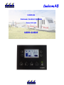
1
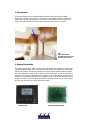
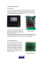
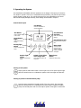
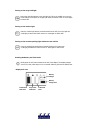
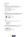
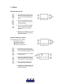
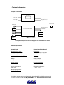
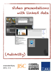
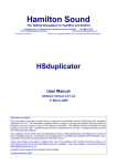
Lindcom
Caravan Control System
Model LIN 900
USER GUIDE
Contents
1. Introduction
2. System Description
3. Main Features
4. Description of the Units
Control Panel
Power Distribution Board
5. Operating the System
6. Display Modes
7. Settings
8. Technical Information
Typical connection diagram
Technical Specification
1. Introduction
The LIN 900 Caravan Control system facilitates the control and monitoring of essential
functions in a caravan, motor home or even a boat. A control panel mounted in a convenient
location gives the user the possibility to easily switch on and off devices such as lights and
water pump and to monitor tank levels, battery status and fuses, all from one place.
Left:
The Control Panel
mounted just next to the
entrance in a caravan
2. System Description
The system consists of two units; a Control panel, with buttons and a graphic LCD display and
a Power distribution board, which are connected with cabling. The control panel is the “brain”
and the user interface. It should be mounted in an easy-to-access location inside the caravan.
The Power distribution board works as “slave” to the Control panel, it features a number of
connectors and relays and distributes the 12V power to the various devices mounted in the
caravan. It is generally mounted close to the battery in order to minimize voltage drop and to
simplify the wiring. The Power distribution board is controlled entirely by the Control panel,
thus, the user does not even need to know that it exists.
Control Panel
Power Distribution Board
3. Main Features
1.
Tank level monitoring
The Control Panel monitors the level in the fresh water tank, the waste water (Grey
water) tank and in the toilet tank. The fresh and grey water tank monitoring has four
levels (25%, 50%, 75% and 100%). The toilet tank monitoring has two levels. (Full/not
full). The levels are displayed graphically on the Control Panel.
An alarm will be triggered if the fresh water falls below the 25% level, or the grey water
reaches the 75% level, or if the toilet tank is full. The display then flashes a symbol
showing which condition(s) has occurred.
2.
Battery monitoring
The caravan battery is constantly monitored. If the battery voltage drops below 11.4V
the battery alarm is triggered. The display then shows a symbol of an empty battery.
3.
Built-in Fuse box with fuse monitoring
The back of the Control Panel is fitted 16 standard car fuses. Three of the fuses are
reserved for certain functions, while the rest are open-ended and their use can be
decided by the caravan builder.
All fuses except F16 are monitored and trigger an alarm if any fuse blows. The display
then shows the blown fuse’s ID (F1 to F15) together with graphical presentation
showing the position of the fuse in the fuse panel, which facilitates identification of the
blown fuse.
(Fuse F16 supplies the Panel itself and can therefore not be monitored).
4.
Built-in Alarm function
As mentioned above, all the monitoring functions come with automatic an alarm that
notifies the user that something needs attention. When an alarm condition is detected
by the system, the display goes into alarm mode, displaying a symbol which tells the
user what has caused the alarm. The alarm display will stay on for 10 seconds and will
repeat every 3 minutes until the condition has been rectified.
5.
Real-time Clock
The Control Panel has a built-in real-time clock and calendar with battery back-up. The
back-up battery keeps the clock going for at least a month if the main battery is
disconnected of flat.
6.
Panel Display back-lighting
The Control Panel display has two independent settings of the back-light intensity for
day and night in order to have an easy-to-read display in daylight, yet without having a
annoyingly bright display at night time. Each brightness level can be adjusted
individually from 0 to 100%. Start time for day and night time display brightness can be
set from 0 to 24 hours.
7.
Language independent Display
All display messages are presented in the form of graphic symbols. This makes the
system totally language independent.
8.
Water pump switching
The water pump supply is switched on with a switch on the Control Panel. The water
pump then starts automatically when a tap is opened. If the caravan has an external
water supply connection, the water pump is generally not needed when connected to
external water supply at a campsite. The pump can then be switched off to prevent it
from running as soon as a tap is opened.
9.
Built-in switches for external lights
The Control Panel has two switches external lights. These are normally connected to the
main outdoor light and to the cargo hold light respectively. This saves the user from
having to search for a light switch in the dark.
10.
Ability to use the Parking/Position lights without the tow vehicle connected.
The Parking light switch on the Control Panel allows the Parking/Position lights to be
switched on without the tow vehicle being available. This is very useful if the caravan is
parked by it self close to traffic in the dark.
11.
Automatic switching of the power from the tow vehicle
When towing the caravan, charging of the caravan battery and the fridge is powered
from the tow vehicle’s alternator. This is accomplished by activating relays Re1 and Re2
on the Power Distribution Board. The relay control signal should be connected to a
power source which is activated by the tow vehicles ignition switch. (In northern
European countries this achieved by connecting it to the parking light, which comes on
automatically when the car is started.)
When the tow vehicle is stopped, the relays then disconnect the supply from the tow
vehicle in order to prevent draining of the car battery. This is particularly important
when bush camping, as the car battery then under no circumstances can be allowed to
be drained.
12.
External start of heater (or A/C)
If the caravan will be left at a campsite in cold weather, the heating of the caravan can
be prepared by switching on the heater and then switching off the main switch on the
Control Panel and then disconnect the 240V supply to the caravan.
The system will then remember that the heating was on, and will automatically start the
heating system as soon as the 240V supply is reconnected. Thus it’s possible to call
somebody and ask them to just connect the 240Vsupply in advance (without having to
give them a key), and the caravan will be warm and cosy upon arrival back.
This feature has proved very popular when camping in cold climates.
4. Description of the Units
The Control Panel
The front of the Control Panel features a back-lit, graphical LCD display and a number of
buttons for user interaction. The panel has a built-in micro controller which is the “brain” of
the system. Commands from the user, and signals from different sensors are passed on to
the micro controller which processes the signals and decides what action needs to be taken,
such as to display a message or to activate an output.
Control Panel Front (Info mode display)
The back of the control panel is fitted with 16 fuses
for the different 12V devices in the caravan. All the
Back of Control Panel
fuses except one are monitored by the system. If a
fuse blows, the display goes into alarm mode,
showing which fuse is blown.
In order to be able to easily replace a blown fuse, the panel should be mounted so that the
back of the panel is readily accessible. The Control Panel is usually used together with the
Power Distribution Board, but it can also be used by itself. In this case external relays are
needed to control high current devices such as a water pump or high wattage lights.
The Power Distribution Board
The Power Distribution Board is used as “junction
box”. It connects together the wiring from the
battery, charger, booster, tow connector, 12V
outlets, fridge, kitchen, bathroom, tail light ramp
etc. It should be mounted close to the caravan
battery in order to minimise voltage drop. The
board is fitted with relays which are controlled by
the control panel. The relays are used for switch
the charging and the fridge supply to the tow
vehicle, switching on the water pump and for
switching on the parking lights when the tow
vehicle isn’t connected.
Power Distribution Board
5. Operating the System
User friendliness and reliability has been paramount in the design of the system, it’s therefore
very simple to operate. There are no complicated setup procedures, just push the main switch
and the system is ready to go. The only two things that are user adjustable are the Time &
Date and the Display backlight intensity; these settings are described in chapter 7.
Control Panel layout
LCD Display
Presents Time & Date or
system Information
Info Button
Arrow Buttons
Up/Down
Press to change display
to info mode
Used when changing
settings
Arrow Button
Right
LED Indicators (x5)
Used when changing
settings
Indicates if button is ON or
OFF
Parking light
switch
Main Switch
Turns the power
on/off to all 12V
devices, except the
outdoor and dining
area lights.
Turns the parking lights
on/off
Outdoor light
switch
Turns the outdoor light
on/off
Switch for the lights
in the Cargo hold
Water Pump
Switch
Turns the light on/off in the
cargo hold
Enables the water pump.
Turning on the system
Simply press the main switch button in lower right corner of the panel. A green light
above the switch comes on to indicate the system is ON. Press again to switch OFF
Turning on power to the fresh water pump
Press the water pump button located just left of the main switch. The green light
above the switch comes on to indicate that the water pump is enabled. The water
pump won’t actually start until one of the taps is opened. Press again to switch OFF.
Turning on the cargo hold light
Press cargo hold light button to turn the light ON. This is the middle one in the row
of five buttons on the panel. A red light just above the button comes on. Press again
to switch OFF.
Turning on the outdoor light
Press the outdoor light button, located second from the left, to turn the light ON.
A red light just above the button comes on. Press again to switch OFF.
Turning on the caravans parking light without the tow vehicle
Press the parking light switch button located leftmost in the button row.
A red light just above the button comes on. Press again to switch OFF.
Checking the Battery and Tank levels
Briefly press the info button located to the left of the display. The display changes
over to info view, which stays on for 10 seconds and then goes back to default view.
Display Info view
Battery
voltage
Battery
charge level
Fresh water
tank level
Grey water
tank level
Toilet tank
level
6. Display modes
Default view
When the main switch is turned on the display shows the default view.
The default view displays time and date together with a “mains connected” notification in
form of “plug” symbol that shows up when 240V mains supply is connected.
Default view
Info view
By pressing the
button located just to the left of the display, the Info view is enabled.
The info view gives a graphical representation of the levels in the fresh water tank, the waste
water tank and the toilet tank. It also displays the battery voltage and charge level.
Info view
Alarm view
The Alarm view comes up automatically if any of the following conditions occurs;
-
Empty fresh water tank
Full waste water tank
Full toilet tank
Low battery voltage
Blown fuse
A symbol on the display will show which condition has caused the alarm. The alarm display
will stay on for 10 seconds and will repeat every 3 minutes.
Note: Fuse F16 supplies the panel itself, so if F16 blows, the display will go out.
Alarm view
7. Settings
Setting the time and date
1. Press both the up and down arrow
buttons and hold for three seconds
to enter time and date adjustment
mode.
2. When the first digit flashes, adjust
with the up/down arrow buttons to
the desired setting.
3. Move to the next digit by pressing
the arrow right button and adjust
the next digit with the up/down
buttons
4. Repeat step 3 to adjust the rest. The
settings will be saved automatically
after a few seconds.
Setting the display back lighting
The back lighting has four settings;
- Day intensity 0-100%
- Start time for day intensity
- Night intensity 0-100%
- Start time for night intensity
1. Press both the up and down arrow
buttons and hold for three seconds to
enter time and date adjustment mode.
2. Press the “i” to continue to setting of
the back lighting.
3. When the first digit flashes (day time
intensity), adjust with the up/down
arrow buttons to the desired setting.
4. Move to set the day start time by
pressing the right arrow button.
5. Repeat step 4 to adjust the rest. The
settings will be saved automatically
after a few seconds.
8. Technical Information
Principal of connection
Control Panel
Interior lights
Fresh Water Sensor
Exterior lights
Gray Water Sensor
Tow Connector
Water pump
Water Tap Switches
Charger
Toilet Switch
Power Distribution Board
Tail light ramp
Booster
Fridge
Aircon/
Heater
Battery
Marker/Position lights
The simplified diagram above shows the typical main connections in a caravan
Technical Specification
Control Panel:
Power Distribution Board:
Dimensions front panel:
160(W) x 130(H) x 4(D)mm
Dimensions:
180(W) x 152(H) x 36(D)mm
Dimensions behind mounting panel:
144(W) x 205(H) x 40(D)mm
Weight:
300 grams
Weight:
615 grams
Supply Voltage:
10-14.5VDC
Supply Voltage:
10-14.5VDC
Current consumption:
max 200mA
Current consumption:
max 350mA
Operating temperature:
-20 ̊ C - +70 ̊ C
Operating temperature:
-20 ̊ C - +70 ̊ C
The Lindcom caravan systems are distributed in Australia and NZ by H2O Electronics Pty Ltd.
For more information please call (08) 9593 8883 or visit www.h2oelectronics.com.au