1
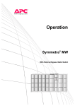
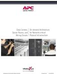
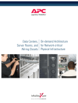
SmartNA 10G Filtering TAP
User Guide
Table of Contents
1
2
3
4
Introduction ...................................................................................................................... 3
Appliance Overview........................................................................................................... 4
Installation ........................................................................................................................ 6
Configuration..................................................................................................................... 7
4.1
4.2
5
6
Startup ............................................................................................................................ 12
Reports ............................................................................................................................ 13
6.1
6.2
7
Reports Overview...................................................................................................................................... 13
Built-In Profiles .......................................................................................................................................... 15
Filtering on Each Monitoring Port .................................................................................... 17
7.1
7.2
7.3
7.4
7.5
8
9
Network Setup ............................................................................................................................................ 7
Setup Options.............................................................................................................................................. 8
Filters Page Overview................................................................................................................................ 17
Filter Overview .......................................................................................................................................... 18
Creating Filters .......................................................................................................................................... 19
Burst Capture ............................................................................................................................................ 20
Filter Examples ......................................................................................................................................... 21
Getting Help .................................................................................................................... 23
Specifications and Safety ................................................................................................. 24
© 2008 Network Critical NA, LLC. All rights reserved. Network Critical is a trademark of Network Critical NA,
LLC. All other trademarks are the property of their respective owners.
2
1 Introduction
Network Critical’s SmartNA 10G Filtering TAP is an intelligent tap for 10G networks. The SmartNA 10G Filtering
TAP inspects every bit in every packet at full duplex 10 Gigabits per second, allowing users to selectively duplicate
only the traffic of interest to either 10G or 1G ports, thereby enhancing the utility of existing tools or enabling the
creation of entirely new applications.
Key features of the SmartNA 10G Filtering TAP include:
•
•
•
Selective Regeneration
Traffic Statistics – LCD, Web-based and Emitted
Integrated Passive Bypass
Selective Regeneration
Selective regeneration is a powerful form of bandwidth reduction that enables systems attached to the SmartNA
10G Filtering TAP to have access to a useful subset of full line rate 10G traffic without being overwhelmed by high
packet rates. For example, a laptop running packet analysis software can be connected to a 10G link and a filter
can be set to duplicate only relevant packets for debug (say ICMP packets with a particular payload) and instead of
receiving the entire 10G link, the laptop receives only the relevant packets.
Drilling Down
The SmartNA 10G Filtering TAP’s filtering capabilities enable drilling down on a particular network segment,
allowing network monitoring tools to generate reports for only the end points of interest. Other examples include
selectively duplicating traffic from specific users to satisfy compliance policies, detecting passwords in the clear or
the detection of unauthorized applications running over non-standard ports (port masquerading).
Integrated Passive Bypass
Integrated passive bypass allows the SmartNA 10G Filtering TAP to continue to pass traffic even in the event of a
power outage.
Traffic Statistics
The SmartNA 10G Filtering TAP provides basic statistics for network behavior in three ways: the LCD, web reports
and with an open data format. The LCD continuously displays total network traffic passing through the SmartNA
10G Filtering TAP as well as a breakdown into major protocol groups (TCP, UDP, ARP, ICMP, OTHER), TCP events
and TCP window size, giving an instant view into the wire. The same statistics and user defined filter information is
available via a browser, making network behavior data available anywhere.
Simple Drop-in Deployment
Deployment of a SmartNA 10G Filtering TAP is as simple as connecting the monitor ports to the network, setting
the IP address of the management port, connecting the selective regeneration ports to packet capture equipment
and providing power.
Reliability
The SmartNA 10G Filtering TAP’s high performance and reliability is derived from the utilization of an all hardware
data path. By transferring complexity into a custom ASIC, the SmartNA 10G Filtering TAP can run a lightweight
hardened OS, making its embedded software both simple and resistant to security attacks. The integrated passive
bypass means no interruption to the network.
3
2 Appliance Overview
The SmartNA 10G Filtering TAP’s ports and controls are shown in the figure below.
LIVE NETWORK
PORTS
MONITORING
PORTS
INFORMATION
DISPLAY
MANAGEMENT
CONTROL PAD
cPacket
cPacketNetworks
Networks
POWER
INDICATOR
LINK/ACTIVITY
STATUS
Figure 1: SmartNA 10G Filtering TAP - Front View
The front of the SmartNA 10G Filtering TAP has six network interfaces. The function of these ports is described
below.
Live Network Ports – Full duplex 10G interfaces to monitor network
traffic. These ports do not have IP or MAC addresses and are fully
transparent to other network appliances. The ports are linked with an
integrated bypass and will continue to pass traffic under all conditions.
Monitoring Ports – Duplicates network traffic selectively according to
filters set on the SmartNA 10G Filtering TAP. The 10G and 1G duplicate
ports can be connected to a standard computer running packet analysis
software or to a dedicated capturing appliance.
Management Port – Used to manage the SmartNA 10G Filtering TAP,
view reports and send network behavior data. This port has an IP
address (shown on the LCD) and is SSL secured.
Status LEDs – Each port has status LEDs to indicate link conditions:
A, B (LC connector)
Error
Transmit activity (blink = activity)
Link/receive activity (solid = link, blink = activity)
1, 2 (LC connector)
Transmit activity on port 2 (blink = activity)
Transmit activity on port 1 (blink = activity)
3, 4, MANAGEMENT (RJ-45):
Error
10/100 link/activity (solid = link, blink = activity)
Gigabit link/activity (solid = link, blink = activity)
To the right of the network ports are an information display and a control pad. They are used to display network
traffic conditions as well as manage and configure the SmartNA 10G Filtering TAP operation. The network visibility
screens are shown below; see section 4.2 for information on using the LCD to configure the SmartNA 10G Filtering
TAP.
4
Receive
bps
pps
A:1,234,567k 12,345k
B: 1,234,567 12,345
Port A, B Receive Bandwidth – Displays the current rate of traffic being
received through ports A and B in bits/second and packets/second.
10G Duplicate
bps
pps
1:1,234,567k 12,345k
2: 1,234,567 12,345
10G Duplicate Bandwidth – Displays the current rate of traffic being
transmitted out of the 10G duplicate ports 1 and 2 in bits/second and
packets/second.
1G Duplicate
bps
3: 1,234,567
4: 1,234,567
1G Duplicate Bandwidth – Displays the current rate of traffic being
transmitted out of the 1G duplicate ports 3 and 4 in bits/second and
packets/second.
pps
12,345
12,345
arp
bps
A: 1,234,567
B: 1,234,567
Model:
S/N:
H/W ver:
S/W ver:
pps
12,345
12,345
SNA10G
12345
5
4349/4543
Port Link Status
A
B
3
4 MGT
10G 10G ... ... 100
Addr:192.168.003.125
Mask:255.255.255.000
GW: 000.000.000.000
√=change any x=back
Built-in Traffic Statistics – In addition to total bandwidth, the LCD
displays traffic statistics for 15 built-in traffic types. These types are:
arp, tcp, udp, icmp, ipv4, ipv6, other (traffic not matching the above),
tcp_syn, tck_syn_ack, tcp_fin, tcp_rst, tcp window size =0, tcp window
size < 256, tcp window size < 1024 and tcp window size > 1024.
Version, Model, Serial Number – Displays the version, serial number,
model of the system and fiber type. To access this screen, open the
“Top Menu” by pressing the back button, then select “Device Info” by
pressing down and view by pressing the green check button (√).
Port Status – Displays port link status. The network ports show 10, 100
If no link exists, the display shows ...
(three periods). Port 1 and Port 2 are always 10G and active so they are
not shown. To access this screen, open the “Top Menu” by pressing the
back button, then select “Port Link Status” by pressing down and view
by pressing the green check button (√).
GIG or 10GIG for link speed.
Management Port IP Address and Netmask – The top line displays the
IP address for the management port, the second shows netmask, and
the third is the gateway address. If the gateway is all zeros, then it is
disabled. To access this sceen, open the “Top Menu” by pressing the
back button, then select “Configuration”, then “Mgmt IPv4 Config.”
5
3 Installation
The SmartNA 10G Filtering TAP can be mounted in a standard 19” rack and occupies 1 rack unit. To deploy in this
configuration, attach the supplied mounting brackets to the appliance and attach it to the desired rack location.
Step 1: Attach mounting brackets to the SmartNA 10G Filtering TAP.
Attach a mounting bracket to each side of the SmartNA 10G Filtering TAP using the three screws supplied.
Step 2: Attach the SmartNA 10G Filtering TAP to the rack.
Install the SmartNA 10G Filtering TAP in the rack using the four large rack mounting screws supplied.
Step 3: Supply power to the appliance.
Connect the power cord to the connector on the rear of the SmartNA 10G Filtering TAP.
Step 4: Power up the SmartNA 10G Filtering TAP
Flip the power switch on the rear of the SmartNA 10G Filtering TAP to ON (the ‘1’ position).
6
4 Configuration
This section describes the installation of the SmartNA 10G Filtering TAP into the network as well as how to
configure the SmartNA 10G Filtering TAP.
4.1
Network Setup
Step 1: Connect the Management Port
Connect the management port to your network.
Step 2: Connect Monitoring Ports
Connect the monitoring ports to the systems running software for the further analysis of packets (e.g. Wireshark,
ntop, etc.). See section 4.2 for configuring the operation of these ports.
Step 3: Connect Live Network Ports
The SmartNA 10G Filtering TAP is a fully transparent network appliance with integrated fiber bypass. Traffic will
continue to flow in both directions even without power to the device. The SmartNA 10G Filtering TAP is deployed
between any two network devices and transparently bridges the link. To install the appliance, simply connect the
A and B ports between two branches of the network as shown in Figure 2. In addition, it is possible to monitor and
provide bandwidth reduction on two different links by connecting each receive port separately.
Figure 2: Deployment – Connectivity
7
4.2
Setup Options
SmartNA 10G Filtering TAP configuration items include:
• Network configuration - IP address, gateway, netmask
• Username and password configuration
• Monitoring (duplication) port configuration
SmartNA 10G Filtering TAP Setup – LCD and Control Pad
IP address Configuration
To change the IP address configuration, press the (X) button until you reach the "Top Menu", then scroll to
"Configuration" and select it by pressing the check button (√); then select "Mgmt IPv4 Config". The following
screen will be presented:
Mgmt IPv4 Config
Adr:192.168.003.125
Msk:255.255.255.000
√=change any x=back▼
(A down or up arrow (▼▲) appearing in the lower or upper right corners of the LCD indicates there are more items
below or above the items currently displayed; use the up and down arrows to see additional menu items.)
Press the check button (√) to modify. A list of modifiable options will be shown. These are the address, mask, and
gateway. Select "Mgmt IPv4 Address".
Mgmt IPv4 Config
*Address
Netmask
√=select, x=back
▼
Press the left and right buttons to select a digit. Press up and down to modify the digit. Press the check button to
accept the new address.
Mgmt IPv4 Address
192.168.003.125
√=accept, x=cancel ▼
After at least one of the settings has been modified, these changes must be saved. The top line of the LCD will flash
between "(NOT SAVED)" and the menu title.
(NOT SAVED)
*Mgmt IPv4 Address
Mgmt IPv4 Mask
√=select, x=back
▼
To save settings, press and hold the green check button (√) for three seconds. A confirmation menu will appear.
Save changes?
√=yes
x=no
8
Press the green check button (√) to save the changes, the red (X) button to cancel the changes. Wait while the
SmartNA 10G Filtering TAP saves the changes and restarts.
Other network settings are configured in the same manner. The Mgmt IPv4 Config menu configures:
•
•
•
•
•
•
•
Address
Netmask
Gateway
DNS1 Address
DNS2 Address
Allow Ping
Web TCP Port
Time and NTP Configuration
To change the Time and NTP configuration, press the (X) button until you reach the “Top Menu”. Scroll to
“Configuration” and select it. Select “Date&Time Config”. The following screen will be presented:
Date & Time
2008-02-11 17:20:26
Time Zone: GMT
√=change any x=back▼
Press the check button (√) to modify. A list of modifiable options will be shown. These are the address, mask, and
gateway. Select "Mgmt IPv4 Address".
Date&Time Menu
*NTP Mode
NTP IPv4 Address
√=select, x=back
▼
Select a parameter to modify and press (√). Modify the desired value by using the left and right buttons to move
amongst fields and the up and down buttons to change the value. After at least one of the settings has been
modified, these changes must be saved. The top line of the LCD will flash between "(NOT SAVED)" and the menu
title.
(NOT SAVED)
*NTP Mode
NTP IPv4 Address
√=select, x=back
▼
To save settings, press and hold the green check button (√) for three seconds. A confirmation menu will appear.
Save changes?
√=yes
x=no
Press the green check button (√) to save the changes or the red (X) button to cancel the changes. Wait while the
SmartNA 10G Filtering TAP saves the changes and restarts.
Other network settings are configured in the same manner. The Date&Time menu configures:
•
•
•
NTP Mode
NTP IPv4 Address
NTP Hostname
9
•
•
Date & Time
Time Zone
Mirroring Config -> Port Rate Limit
The Port Rate Limit menu is used for setting rate limiting for the 1G ports (ports 3 and 4). The ports can each be
set to one of ten different rate limit values, specified in either packets per second or bits per second.
To configure the port rate limit, press the (X) button until you reach the “Top Menu”. Scroll to “Configuration” and
select it. Select “Mirroring Config” then “Port Rate Limit”. The following screen will be presented:
Port Rate Limit
1:off
2:off
3:100 pps 4:100mbps
√=change any x=back
Press (√)to modify any of these fields (use cursor up/down to select a rate limit, left/right to move between ports),
then press and hold the (√) for three seconds to save.
Front Panel Setup
The Front Panel Setup menu is used to configure the brightness and contrast of the LCD, a screensaver and an “idle
screen” that the LCD returns to after being inactive for five minutes.
To configure the front panel settings, press the (X) button until you reach the “Top Menu”. Scroll to
“Configuration” and select it. Select “Front Panel Setup”. The following screen will be presented:
Front Panel Setup
Idle:Receive
Bri 100%, Cont 45%
√=change any x=back▼
Press (√) to modify any of these fields, then press and hold the (√) for three seconds to save.
Security
For security purposes, an 8-16 digit PIN is available to allow only administrators to change configuration items on
the SmartNA 10G Filtering TAP. To change or set the admin PIN, press the (X) button until you reach the “Top
Menu”. Scroll to “Security” and select it. Select “Reset Admin PIN”. The following screen will be presented:
Security
Reset Admin PIN
√=select
x=back
Press (√) to enter or modify the PIN. PINs must be between eight and 16 digits in length. Selecting a PIN of zero
length turns off the admin PIN security feature. After configuring the PIN, press and hold the (√) for three
seconds to save.
10
SmartNA 10G Filtering TAP Setup – Web-based Config
Network configuration - IP address, gateway, netmask, NTP and web port
This section is used to specify the networking configuration of the SmartNA 10G Filtering TAP. In addition to the
standard network settings, the web_port parameter allows configuration of which port the web server operates,
e.g. https://address:web_port.
Example:
###################################
# NETWORK SETTINGS
#
###################################
# ip settings
ip_address 192.168.0.121
gateway 0.0.0.0
netmask 255.255.255.0
ping_enable yes
# dns settings
dns1 0.0.0.0
dns2 1.1.1.1
# time setting
ntp_address 192.168.3.1
ntp_hostname local.ntp.server
ntp_enable no
timezone 0
# server setting (port over which browser is used, e.g. https://address:web_port)
web_port 443
Username and password configuration
This section specifies the users and passwords of admin users and regular users. Regular users can only view the
web-based reports. Admin users are additionally allowed to change filtering/selective regeneration options and
configure the SmartNA 10G Filtering TAP. Multiple admin and regular users may be specified but at least one
admin user must be specified.
Example:
####################################
# USERNAME/PASSWORD CONFIGURATION #
####################################
# multiple admins or users are supported.
# administrative username and password, creates user for reports and filter specification and settings
admin
admin
admin
# user username and password, creates user for web reports only
user
user
user
The Port Rate Limit menu is used for setting rate limiting for the 1G ports (ports 3 and 4). The ports can each be
set to one of nine different rate limit values, specified in either packets per second or bits per second.
Example:
#
#
#
#
#
Rate limiting for 1G mirror ports. Ports 3 and 4
can each be rate limited by either pps (packets per second)
or bps (bits per second).
#
#
#
#
#
#
#
0 off
1
2
3
4
5
100
1
10
50
100
pps
kpps
kpps
kpps
kpps
(
(
(
(
1,000
10,000
50,000
100,000
pps)
pps)
pps)
pps)
#
#
#
#
6
7
8
9
100
1
10
100
kbps
mbps
mbps
mbps
(
100,000
( 1,000,000
( 10,000,000
(100,000,000
bps)
bps)
bps)
bps)
Available values are:
mirror_3_ratelimit 0
mirror_4_ratelimit 0
11
5
Startup
Now that the hardware and networking components are installed and configured, it’s time to start the SmartNA
10G Filtering TAP. This section describes startup and allows you to confirm that the SmartNA 10G Filtering TAP is
operating properly. Operation of the SmartNA 10G Filtering TAP is described in the following sections.
Step 1: Start SmartNA 10G Filtering TAP device
Turn on the SmartNA 10G Filtering TAP.
Step 2: Observe bandwidth on SmartNA 10G Filtering TAP LCD
Go to a SmartNA 10G Filtering TAP appliance that is installed on a link that currently has network traffic. Push the
LCD toggle button until the Receive screen appears and confirm that there is traffic flowing through the SmartNA
10G Filtering TAP.
Receive
bps
pps
A:1,234,567k 12,345k
B: 1,234,567 12,345
Step 3: View Reports
1. Enter https://address from a computer that has access to the SmartNA 10G Filtering TAP, where address
is the address assigned to the device.
2. Use the default login and password supplied by Network Critical and verify that the reports are now active
by selecting the current link.
Note: Please use Firefox version 2.0 or greater as your browser for greater compatibility.
12
6 Reports
The SmartNA 10G Filtering TAP reports provide information on network behavior information such as protocol
breakdown, TCP events and TCP window size. The information is presented in a set of tables that show the current
(instantaneous) value and statistics such as minimum, maximum, mean and standard deviation (derived from the
past 60 seconds).
The tables are viewable using a web browser. JavaScript is required and the link between the browser and the
SmartNA 10G Filtering TAP is secured with SSL.
A selection of standard reports is built into the SmartNA 10G Filtering TAP. These reports are described in more
detail in the following sections. As additional filters are defined, statistics for these filters are automatically added
to the report. Reports update continuously in real time and can be paused.
6.1
Reports Overview
Figure 3 – 5 show the three reports pages, current, statistics and cumulative, respectively. The current page
displays the current bits per second, packets per second and percentage bits per second and packets per second
for each traffic profile or filter. The statistics page adds minimum, mean, maximum and standard deviation. The
cumulative page, rather than showing rates, shows the total number of bytes and packets. Any page can be
paused by clicking on the pause link. To resume realtime viewing, click play. The tables can be sorted by clicking
on the column headers; an up or down arrow will appear to indicate the sorting order.
Figure 3: Current Page
13
Figure 4: Statistics Page
NAVIGATION
PLAY/PAUSE
CLEAR
PER PORT
BANDWIDTH
PER RULE/FILTER
STATISTICS
Figure 5: Cumulative Page
14
6.2
Built-In Profiles
A set of profiles are built-in to the SmartNA 10G Filtering TAP and are always available. These profiles provide
basic information about network behavior and are described below. As additional selective regeneration or
duplication filters are defined, they are automatically added to these reports. Creation of filters is explained in
section 7.
Protocol Breakdown
The protocol breakdown profiles show the amount of IPv4, IPv6, TCP, UDP, ICMP, ARP and OTHER (OTHER is
defined as everything that is not from the previous list) traffic for Ports A and B. This report is good for getting a
quick view of overall network behavior.
Figure 6: Protocol Breakdown
TCP Events
These profiles show key TCP traffic types: SYN, SYN_ACK, FIN, and RST. Unbalanced TCP behavior such as
mismatched ratios of SYN to SYN_ACK may indicate connectivity or configuration problems in the network.
15
Figure 7: TCP Events
TCP Window Size
These profiles provide information about TCP window size, a key measure of health on the network. TCP window
sizes of 0, less than 256, less than 1024 and greater than 1024 are counted.
Figure 8: TCP Window Size
16
7 Filtering on Each Monitoring Port
The SmartNA 10G Filtering TAP features filtering capabilities on each monitoring port. Traffic entering the live
ports (A and B) can be duplicated to up to four (4) monitoring ports:
• Port 1: 10 Gigabit Monitoring Port (LC Connector) provides a copy of live network traffic A ->B
• Port 2: 10 Gigabit Monitoring Port (LC Connector) provides a copy of live network traffic B ->A
• Port 3: 1 Gigabit Aggregated Monitoring Port (RJ-45) providing an aggregated copy of live network traffic
(A ->B & B->A)
• Port 4: 1 Gigabit Aggregated Monitoring Port (RJ-45) providing an aggregated copy of live network traffic
(A ->B & B->A)
This filtered regenerations functions as selective bandwidth reduction, enabling systems attached to the SmartNA
10G Filtering TAP to have access to full line rate 10G traffic without being overwhelmed by the high packet rate.
For example, a laptop running Wireshark (open source packet analysis software) can be connected to a 10G link
and a filter can be set to duplicate only relevant packets for a debug (say ICMP packets with a particular payload).
Instead of receiving the brunt of the 10G link, the laptop only receives a trickle of relevant packets. Another
example is to use the SmartNA 10G Filtering TAP’s filtering capabilities to drill down on a particular network
segment, allowing network monitoring tools such as ntop (open source network monitoring) to generate reports
for only the relevant end points. Other examples include selectively duplicating traffic to satisfy compliance
policies, detecting passwords in the clear or detecting unauthorized applications running over non-standard ports
(port masquerading).
OPTIONAL
FILTERING
FILTERING
AGGREGATION
REDUCTION
Network Critical
Figure 9: SmartNA 10G Filtering TAP Port Relationship
7.1
Filters Page Overview
The regeneration filters are managed from the filters page. The main page is arranged into sections as described
below.
Figure 10: Filters Page
17
NAVIGATION
Provides access to the current, statistics, burst capture, and settings pages. Burst capture, filters and settings
require admin level access, standard users can access only the current and statistics pages.
SAVE FILTERS
Saves all filters onto the SmartNA 10G Filtering TAP. Filters with errors will be indicated. Because the filters are
saved on the SmartNA 10G Filtering TAP, they may be edited later.
EXPAND | COLLAPSE
Expands or collapses the filter. When collapsed, only the filter controls are shown. If the filter is expanded, the
filter specification and status lines are shown. If an error occurs, filters with errors are automatically expanded.
FILTERS
Descriptions of the operation of filters can be found in the following section.
7.2
Filter Overview
Each filter is divided into three sections. The top section is a control section and provides controls for
activating/deactivating filters, selecting which ports to duplicate FROM and which ports to duplicate TO, setting
the name of the filter, choosing from filter types, and burst capture. The middle section contains fields specific to
each filter template and is used to enter selective regeneration or duplication criteria such as IP addresses and
payload. The bottom section reports status as well as error messages and also displays the amount of traffic
matching the specified filter. A typical filter is shown in Figure 11.
Figure 11: Filter Overview
EXPAND/COLLAPSE
Expands or collapses the filter. When collapsed, only the filter controls are shown. If the filter is expanded, the
filter specification and status lines are shown. If an error occurs, filters with errors are automatically expanded.
FILTER ACTIVATE/DEACTIVATE
Activates or deactivates the filter. A check box indicates the filter is active. Since modification of active filters is
not allowed, editing a filter specification or control will automatically deactivate the filter. Click the activate box to
reactivate.
FILTER NAME
An identifier for the filter, alphanumeric characters and “_”, “-“ characters only, maximum length of 24. Spaces
are not allowed in the filter name.
FILTER TYPE
A pull down that selects the type of filter specification available. Filter types are described in greater detail below.
DUPLICATE FROM/TO PORTS
The 10G port from which traffic will be duplicated or mirrored. Port A can duplicate to ports 1, 3 and 4. Port B can
duplicate to ports 2, 3 and 4. The relationship between the ports is shown in Figure 12.
18
F F
F
F
Figure 12: SmartNA 10G Filtering TAP Port Relationship
BURST CAPTURE ENABLE
Activates burst capture of packets matching the filter specification. This feature is described in more detail in
section 7.4.
7.3
Creating Filters
The SmartNA 10G Filtering TAP comes with a set of filter templates that cover a broad set of networking protocols
and applications. This section explains the basics of specifying filters and walks through some examples.
Entering Values – CIDR masks, port ranges
Most filters contain fields that support entry of CIDR masks and port ranges. CIDR masks for IP addresses are
specified using the standard “/” notation. Port ranges for TCP or UDP ports are specified using a “:” between the
ports. Examples of these are shown below.
Example 1: IPv4 address CIDR
To Specify
192.168.0.0 with anything in the last two octets
Enter
192.168.0.0/16
Example 2: IPv6 address CIDR
To Specify
aaaa:bbbb:cccc:dddd:eeee:ffff:1111:2222 with
anything in the last 64 bits
Enter
aaaa:bbbb:cccc:dddd:eeee:ffff:1111:2222/64
Example 3: Port range
To Specify
Range from 80 to 8080
Enter
80:8080
Entering Values – Payload
The payload specification enables creation of complex filters based on payload inspection anywhere in the packet.
Payload searches can be case insensitive, non-anchored and contain wildcards. Each payload field has several
options as follows:
19
Option
Function
SKIP WORDS
Used to specify an offset specified in 16-bit words from which to begin the search (nonanchored) or specific location to search (anchored).
ANCHORED
Selects between anchored and non-anchored searches from the SKIP WORDS value.
IGNORECASE
Selects case insensitivity searching for text strings.
PAYLOAD
A combination of ASCII or hexadecimal characters with wildcards.
The following conventions are used in payload strings:
•
•
•
•
•
•
•
•
Strings in hexadecimal representation are enclosed between vertical bars, e.g., |01 AB 09|
Strings in ASCII representation are converted to their HEX representation automatically.
Each pair of hexadecimal characters in between vertical bars | | is an octet value.
For example, ABCD is equivalent to |41|B|43 44|
The '.' (dot) represents a “don’t-care” byte. It is supported in both ASCII and HEX notations.
When using ASCII notation the non-alphanumeric characters, including all special characters, need to be
escaped (or alternatively, specified in HEX notation)
White spaces (that are not escaped) are ignored
Search strings are specified in words (an even number of bytes). If the length of the specific search is odd,
a don’t care '.' will be appended.
Here are a few examples of payload specification:
•
•
Hex notation: |6e 65 74 77 6f 72 6b 73| is equivalent to ASCII notation: “network”
Mixed notation: “packet|20 6e 65 74 77 6f 72 6b|" is equivalent to ASCII notation: “packet
network” and to HEX notation: |70 61 63 6b 65 74 20 6e 65 74 77 6f 72 6b|
A dot (.) designates a don’t-care byte, e.g., "packet.|6e 65 74 77 6f 72 6b|" is like the previous example,
but any character (byte) can replace the space (HEX 20) between the two words. The dot can also be used in HEX
notation, e.g. |6e . 74 77 6f 72 6b| is equivalent to “n” followed by any character then “twork”.
7.4
Burst Capture
This feature enables selective remote capturing of packets to pcap files. Packets are selected and captured on the
filters page, then viewed on the burst page.
Step 1: Packet Selection
On the filters page, define or choose a filter that matches the packets to be captured.
Step 2: Packet Capture
After the filter has been chosen, click the box next to BURST in the filter control bar. The status line will indicate
that burst capture is in progress for the duration of the capture, which is roughly ten seconds, and update when
the capture is complete.
Step 3: Packet Download
Following the capture of these packets, they can be viewed on the burst page. On this page, a list of packet
captures will be shown, sorted by time. If no packets were captured, the number of packets for that entry will be
zero. Click on the link to download and view the pcap file (e.g. using packet analysis software). To delete a
capture, click on the ‘x’ hyperlink. A maximum of ten pcaps are saved. Successive captures will automatically
delete older pcaps.
20
Figure 13: Burst Capture Page
7.5
Filter Examples
How do I create a rule to duplicate TCP traffic on my network?
This example takes you from specifying a filter, to duplicating only TCP type traffic. It shows you how to specify a
payload filter, and allows you to see how much traffic (containing the specified phrase) exists on your network in
packets/second and megabits/second.
Step 1: Select the VLAN:IP:(TCP OR UDP) filter type
Enter a name for the rule and specify the type as TCP.
Step 2: Specify FROM/TO ports and TCP protocol
1. Choose a port to copy the traffic FROM.
2.
Choose a port to copy the traffic TO.
3.
Select TCP as the protocol.
Step 3: Activate the TCP traffic filter
1.
Click the activate button, the status line will change to indicate the filter is being activated.
2.
The level of TCP traffic in your network will now be indicated by the counters as part of the filter and on
the current and statistics pages.
21
How do I create a payload filter to count traffic with a specific string?
This example takes you from specifying a filter, to duplicating traffic with a certain payload. It shows you how to
specify a payload filter, and allows you to see how much traffic (containing the specified phrase) exists on your
network in packets/second and megabits/second.
Step 1: Select the STRING MATCH filter type
Enter a name for the rule and specify the type as String.
Step 2: Specify FROM/TO ports, enter payload string
1. Choose a port to copy the traffic FROM.
2.
Choose a port to copy the traffic TO.
3.
Enter the desired payload in the payload field. The |20| is hexadecimal representation of a space.
Step 3: Activate the filter
1. Click the activate button, the status line will change to indicate the filter is being activated.
2.
The level of traffic containing the string specified will be indicated by the counters as part of the filters
shown on the current and statistics pages.
22
8 Getting Help
For additional assistance with the Smart Network Access System, please contact one of our Technical Customer
Support Representatives.
European Support Center
Phone – +44 (0)118 954 3210
North and South American Support Center
Phone – (716) 558-7280
On the Web
Go to www.NetworkCritical.com
Support > Contact Support
23
9 Specifications and Safety
Specifications
Power
Dimensions
Weight
Operating requirements
100 – 240 V AC full range, 50-60 Hz, 60 W
1.7” x 15.3” x 13.1” (H x W x D) – 1U rack-mountable
9 lbs.
0o to 40o C, 32o to 104o F
Specifications are subject to change without notice.
Safety Information
Documentation reference symbol. If the product is marked with this symbol, refer to the
product documentation to get more information about the product.
WARNING
A WARNING in the documentation denotes a hazard that can cause injury or death.
CAUTION
A CAUTION in the documentation denotes a hazard that can damage equipment.
Do not proceed beyond WARNING or CAUTION notices until the hazardous conditions are
understood and appropriate steps have been taken.
Grounding
There must be an interruptible safety earth ground from the main power source to the product’s input wiring
terminals, power cord, or supplied power cord set. Whenever it is likely that protection has been impaired,
disconnect the power cord until the ground has been restored.
Servicing
There are no user-serviceable parts inside this product. Any servicing, adjustment, maintenance or repair must be
performed only by service-trained personnel.
24