1
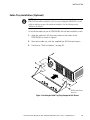
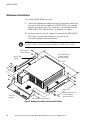
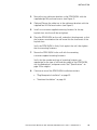
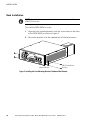
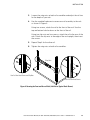
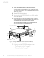
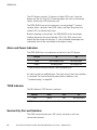
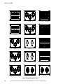
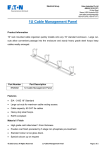
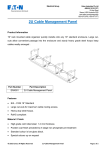
Powerware Series
®
Eaton Rack Power Module
24–96A: 208Y/120V, 400Y/230V
User's Guide
Powerware Series
®
Eaton Rack Power Module
24–96A: 208Y/120V, 400Y/230V
User's Guide
Requesting a Declaration of Conformity
Units that are labeled with a CE mark comply with the following harmonized standards and EU directives:
S
Harmonized Standard: IEC 60950-1:2001
S
EU Directives:
73/23/EEC, Council Directive on equipment designed for use within certain voltage limits
93/68/EEC, Amending Directive 73/23/EEC
89/336/EEC, Council Directive relating to electromagnetic compatibility
92/31/EEC, Amending Directive 89/336/EEC relating to EMC
The EC Declaration of Conformity is available upon request for products with a CE mark. For copies of the EC
Declaration of Conformity, contact:
Eaton Power Quality Oy
Koskelontie 13
FIN-02920 Espoo
Finland
Phone: +358-9-452 661
Fax: +358-9-452 665 68
Eaton, Powerware, BladeUPS, Power Xpert, and X-Slot are registered trademarks of Eaton Corporation or its
subsidiaries and affiliates. Modbus is a registered trademark of Schneider Electric. National Electrical Code and NEC
are registered trademarks of National Fire Protection Association, Inc. All other trademarks are property of their
respective companies.
ECopyright 2007–2010 Eaton Corporation, Raleigh, NC, USA. All rights reserved. No part of this document may be
reproduced in any way without the express written approval of Eaton Corporation.
Special Symbols
The following are examples of symbols used on the UPS or accessories to alert you to important
information:
RISK OF ELECTRIC SHOCK - Indicates that a risk of electric shock is present and the associated
warning should be observed.
CAUTION: REFER TO OPERATOR'S MANUAL - Refer to your operator's manual for additional
information, such as important operating and maintenance instructions.
This symbol indicates that you should not discard waste electrical or electronic equipment (WEEE) in
the trash. For proper disposal, contact your local recycling/reuse or hazardous waste center.
Table of Contents
1
Introduction . . . . . . . . . . . . . . . . . . . . . . . . . . . . . . . . . . . . . . . . . . . . . . . . . . . . . . . . .
9
Safety Warnings . . . . . . . . . . . . . . . . . . . . . . . . . . . . . . . . . . . . . . . . . . . . . . . . . . . . . . . . . . . . . . . . . . . . .
11
Installation . . . . . . . . . . . . . . . . . . . . . . . . . . . . . . . . . . . . . . . . . . . . . . . . . . . . . . . . .
15
Inspecting the Equipment . . . . . . . . . . . . . . . . . . . . . . . . . . . . . . . . . . . . . . . . . . . . . . . . . . . . . . . . . . . . . . .
Tools Required . . . . . . . . . . . . . . . . . . . . . . . . . . . . . . . . . . . . . . . . . . . . . . . . . . . . . . . . . . . . . . . . . . . . . .
Checking the Accessory Kit . . . . . . . . . . . . . . . . . . . . . . . . . . . . . . . . . . . . . . . . . . . . . . . . . . . . . . . . . . . . . .
Cable Tray Installation (Optional) . . . . . . . . . . . . . . . . . . . . . . . . . . . . . . . . . . . . . . . . . . . . . . . . . . . . . . . . . .
Wallmount Installation . . . . . . . . . . . . . . . . . . . . . . . . . . . . . . . . . . . . . . . . . . . . . . . . . . . . . . . . . . . . . . . . .
Rack Installation . . . . . . . . . . . . . . . . . . . . . . . . . . . . . . . . . . . . . . . . . . . . . . . . . . . . . . . . . . . . . . . . . . . . .
Plug-Receptacle Installation . . . . . . . . . . . . . . . . . . . . . . . . . . . . . . . . . . . . . . . . . . . . . . . . . . . . . . . . . . . . .
Hardwired Installation . . . . . . . . . . . . . . . . . . . . . . . . . . . . . . . . . . . . . . . . . . . . . . . . . . . . . . . . . . . . . . . . .
Advanced Metering Installation (Optional) . . . . . . . . . . . . . . . . . . . . . . . . . . . . . . . . . . . . . . . . . . . . . . . . . . .
15
15
16
17
18
20
23
24
28
Operation . . . . . . . . . . . . . . . . . . . . . . . . . . . . . . . . . . . . . . . . . . . . . . . . . . . . . . . . . . .
29
Introduction . . . . . . . . . . . . . . . . . . . . . . . . . . . . . . . . . . . . . . . . . . . . . . . . . . . . . . . . . . . . . . . . . . . . . . . . .
Breakers . . . . . . . . . . . . . . . . . . . . . . . . . . . . . . . . . . . . . . . . . . . . . . . . . . . . . . . . . . . . . . . . . . . . . . . . . . .
Color-Coded Numbering . . . . . . . . . . . . . . . . . . . . . . . . . . . . . . . . . . . . . . . . . . . . . . . . . . . . . . . . . . . . . . . .
LED Display . . . . . . . . . . . . . . . . . . . . . . . . . . . . . . . . . . . . . . . . . . . . . . . . . . . . . . . . . . . . . . . . . . . . . . . . .
Alarm and Power Indicators . . . . . . . . . . . . . . . . . . . . . . . . . . . . . . . . . . . . . . . . . . . . . . . . . . . . . . . . . . . . .
TVSS Indicator . . . . . . . . . . . . . . . . . . . . . . . . . . . . . . . . . . . . . . . . . . . . . . . . . . . . . . . . . . . . . . . . . . . . . . .
Service Only Port and Switches . . . . . . . . . . . . . . . . . . . . . . . . . . . . . . . . . . . . . . . . . . . . . . . . . . . . . . . . . . .
29
30
30
31
32
32
32
4
Specifications . . . . . . . . . . . . . . . . . . . . . . . . . . . . . . . . . . . . . . . . . . . . . . . . . . . . . . .
33
5
Troubleshooting . . . . . . . . . . . . . . . . . . . . . . . . . . . . . . . . . . . . . . . . . . . . . . . . . . . . . .
39
Typical Alarms and Conditions . . . . . . . . . . . . . . . . . . . . . . . . . . . . . . . . . . . . . . . . . . . . . . . . . . . . . . . . . . . .
Service and Support . . . . . . . . . . . . . . . . . . . . . . . . . . . . . . . . . . . . . . . . . . . . . . . . . . . . . . . . . . . . . . . . . . .
39
40
Warranty . . . . . . . . . . . . . . . . . . . . . . . . . . . . . . . . . . . . . . . . . . . . . . . . . . . . . . . . . . .
41
Limited Factory Warranty . . . . . . . . . . . . . . . . . . . . . . . . . . . . . . . . . . . . . . . . . . . . . . . . . . . . . . . . . . . . . . .
41
2
3
6
Eaton Rack Power Module (24–96A: 208Y/120V, 400Y/230V) User's Guide S 164201675 Rev 2
www.eaton.com/powerquality
7
TABLE OF CONTENTS
8
Eaton Rack Power Module (24–96A: 208Y/120V, 400Y/230V) User's Guide S 164201675 Rev 2
www.eaton.com/powerquality
Chapter 1
Introduction
The Eaton® Rack Power Module (RPM-3U/3Ui) is designed to distribute
power within a rack. Providing outstanding performance and reliability,
the RPM-3U/3Ui's unique benefits include the following:
S Provides plug-and-play primary distribution from a three-phase UPS to
secondary power distribution devices. The RPM-3U/3Ui is ideal for
enhancing the output distribution of UPSs such as the Eaton
BladeUPS®.
S Functions in a wide variety of applications supporting various data
center loads at various voltages, power cord configurations, and
layouts.
S Can be installed in any standard 48-cm (19-inch) EIA rack or cabinet in
3U applications with included hardware.
S Can be mounted on a wall with the optional wallmount brackets and
customer-provided fasteners appropriate for the type of wall.
S Organizes power distribution and simplifies cable management,
making it easier to follow the power path to the load. The
RPM-3U/3Ui also improves load balancing, reducing nuisance
overload alarms from the UPS.
S Indicator LEDs that show when incoming power is available to the
RPM-3U/3Ui and when an alarm is present.
S Columns of LEDs labeled to match the output breaker poles and the
input lines. Each column displays a reading of load status.
S Circuit breakers and indicator LEDs located on the front panel for easy
access.
S Plug-receptacle model that is customer-installable without the
services of a licensed electrician, once the main connection to the
UPS is made.
S Backed by worldwide agency approvals.
Eaton Rack Power Module (24–96A: 208Y/120V, 400Y/230V) User's Guide S 164201675 Rev 2
www.eaton.com/powerquality
9
INTRODUCTION
The following options for the RPM-3U/3Ui are available:
S Choice of input power cord lengths:
- 1.8m (6 ft)
- 3.0m (10 ft)
- 4.6m (15 ft)
- 6.1m (20 ft)
S Multiple input options:
- BladeUPS connector (208Y/120V or 400Y/230V)
- IEC 309-60A
- L21-30P
- Hardwired (208Y/120V or 400Y/230V)
S Multiple output receptacle options:
- IEC 320-C13, IEC 320-C19
- 5-15R, 5-20R
- L6-15R, L6-20R, L6-30R
- L14-20R, L14-30R
- L15-20R, L15-30R
- L21-20R, L21-30R
S Surge protection with the optional Transient Voltage Surge
Suppression (TVSS) card.
S Advancing Metering with the Universal Control Board (UCB) and
Power Xpert® Gateway Series 1000 Card.
The RPM-3U/3Ui allows configurations such as:
S Converting three-phase inputs to single-phase outputs to connect to
single-phase rack outlet strips.
S Incorporating three-way splitter cables to split three-phase receptacle
voltage into 3x single-phase receptacles, allowing a single
three-phase receptacle to feed three racks, each containing
conventional single-phase strips with outlets. Such a configuration
could support a minimum of two high-density racks or a maximum of
nine low-density (approximately 2 kVA) racks.
10
Eaton Rack Power Module (24–96A: 208Y/120V, 400Y/230V) User's Guide S 164201675 Rev 2
www.eaton.com/powerquality
INTRODUCTION
Safety Warnings
IMPORTANT SAFETY INSTRUCTIONS
SAVE THESE INSTRUCTIONS
This manual contains important instructions that you should follow during installation and
operation of the RPM-3U/3Ui. Please read all instructions before operating the equipment
and save this manual for future reference.
DANGER
This RPM-3U/3Ui contains LETHAL VOLTAGES. All repairs and service should be
performed by AUTHORIZED SERVICE PERSONNEL ONLY. There are NO USER
SERVICEABLE PARTS inside the RPM-3U/3Ui.
CAUTION
S To reduce the risk of fire or electric shock, install this RPM-3U/3Ui in a temperature and
humidity controlled, indoor environment, free of conductive contaminants. Ambient
temperature must not exceed 30°C (86°F). Do not operate near water or excessive
humidity (95% maximum).
S To comply with international standards and wiring regulations, the total equipment
connected to the output of this RPM-3U/3Ui must not have an earth leakage current
greater than 3.5 milliamperes.
S For PERMANENTLY CONNECTED EQUIPMENT, a readily accessible disconnect device
shall be incorporated in the building installation wiring.
S For PLUGGABLE EQUIPMENT, the power outlet shall be installed near the equipment and
shall be readily accessible.
Eaton Rack Power Module (24–96A: 208Y/120V, 400Y/230V) User's Guide S 164201675 Rev 2
www.eaton.com/powerquality
11
INTRODUCTION
Consignes de sécurité
CONSIGNES DE SÉCURITÉ IMPORTANTES
CONSERVER CES INSTRUCTIONS
Ce manuel contient des instructions importantes que vous êtes invité à suivre lors de toute
procédure d'installation et de fonctionnement de RPM-3U/3Ui. Veuillez consulter
entièrement ces instructions avant de faire fonctionner l'équipement et conserver ce manuel
afin de pouvoir vous y reporter ultérieurement.
DANGER!
Cet RPM-3U/3Ui contient des TENSIONS MORTELLES. Toute opération d'entretien et de
réparation doit être EXCLUSIVEMENT CONFIÉE A UN PERSONNEL QUALIFIÉ AGRÉÉ.
AUCUNE PIÈCE RÉPARABLE PAR L'UTILISATEUR ne se trouve dans la RPM-3U/3Ui.
ATTENTION!
S Pour réduire les risques d'incendie et de décharge électrique, installer la RPM-3U/3Ui
uniquement à l'intérieur, dans un lieu dépourvu de matériaux conducteurs, où la
température et l'humidité ambiantes sont contrôlées. La température ambiante ne doit
pas dépasser 30 °C. Ne pas utiliser à proximité d'eau ou dans une atmosphère
excessivement humide (95 % maximum).
S Afin d'être conforme aux normes et règlements internationaux de câblage, le courant de
fuite à la terre de la totalité du matériel branché sur la sortie de la RPM-3U/3Ui ne doit
pas dépasser 3,5 mA.
S Afin de CONNECTER DE MANIÈRE PERMANENTE L'ÉQUIPEMENT, un dispositif de
déconnexion aisément accessible doit être incorporé au câblage d'installation du
bâtiment.
S En ce qui concerne l'ÉQUIPEMENT ENFICHABLE, la prise d'alimentation doit être
installée près de l'équipement et doit être facile d'accès.
12
Eaton Rack Power Module (24–96A: 208Y/120V, 400Y/230V) User's Guide S 164201675 Rev 2
www.eaton.com/powerquality
INTRODUCTION
Sicherheitswarnungen
WICHTIGE SICHERHEITSANWEISUNGEN
AUFBEWAREN
Dieses Handbuch enthält wichtige Hinweise, welche Sie bei der Installation und Wartung
des RPM-3U/3Ui beachten sollten. Bitte lesen Sie alle Anweisungen des Handbuches bevor
sie mit dem Gerät arbeiten. Bewaren Sie das Handbuch zum Nachlesen auf.
WARNUNG
Die RPM-3U/3Ui führt lebensgefährliche Spannungen. Alle Reparatur- und
Wartungsarbeiten sollten nur von Kundendienstfachleuten durchgeführt werden. Die
RPM-3U/3Ui enthält keine vom Benutzer zu wartenden Komponenten.
ACHTUNG
S Um die Brand‐ oder Elektroschockgefahr zu verringern, diese RPM-3U/3Ui nur in
Gebäuden mit kontrollierter Temperatur und Luftfeuchtigkeit installieren, in denen keine
leitenden Schmutzstoffen vorhanden sind. Die Umgebungstemperatur darf 30°C nicht
übersteigen. Die RPM-3U/3Ui nicht in der Nähe von Wasser oder in extrem hoher
Luftfeuchtigkeit (max. 95 %) betreiben.
S Um internationale Normen und Verdrahtungsvorschriften zu erfüllen, dürfen die an den
Ausgang dieser RPM-3U/3Ui angeschlossenen Geräte zusammen einen Erdableitstrom
von insgesamt 3,5 Milliampere nicht überschreiten.
S Für PERMANENT ANGESCHLOSSENE GERÄTE: In der Gebäudeverkabelung muss eine
leicht zugängliche Trennvorrichtung enthalten sein.
S Für GERÄTE MIT STECKERN: Die Steckdose muss sich in der Nähe des Geräts befinden
und leicht zugänglich sein.
Eaton Rack Power Module (24–96A: 208Y/120V, 400Y/230V) User's Guide S 164201675 Rev 2
www.eaton.com/powerquality
13
INTRODUCTION
Advertencias de Seguridad
INSTRUCCIONES DE SEGURIDAD IMPORTANTES
GUARDE ESTAS INSTRUCCIONES
Este manual contiene instrucciones importantes que debe seguir durante la instalación y el
funcionamiento de la RPM-3U/3Ui. Por favor, lea todas las instrucciones antes de poner en
funcionamiento el equipo y guarde este manual para referencia en el futuro.
PELIGRO
Este RPM-3U/3Ui contiene VOLTAJES MORTALES. Todas las reparaciones y el servicio
técnico deben ser efectuados SOLAMENTE POR PERSONAL DE SERVICIO TÉCNICO
AUTORIZADO. No hay NINGUNA PARTE QUE EL USUARIO PUEDA REPARAR dentro de la
RPM-3U/3Ui.
PRECAUCIÓN
S Para reducir el riesgo de incendio o de choque eléctrico, instale este RPM-3U/3Ui en un
lugar cubierto, con temperatura y humedad controladas, libre de contaminantes
conductores. La temperatura ambiente no debe exceder los 30°C. No trabaje cerca del
agua o con humedad excesiva (95% máximo).
S Para cumplir con los estándares internacionales y las normas de instalación, la totalidad
de los equipos conectados a la salida de este RPM-3U/3Ui no debe tener una intensidad
de pérdida a tierra superior a los 3,5 miliamperios.
S Para EQUIPO CONECTADO PERMANENTEMENTE, se debe incorporar un dispositivo de
desconexión fácilmente accesible al cableado de la instalación del edificio.
S Para EQUIPO ENCHUFABLE, la salida de alimentación debe estar instalada cerca del
equipo y estar fácilmente accesible.
14
Eaton Rack Power Module (24–96A: 208Y/120V, 400Y/230V) User's Guide S 164201675 Rev 2
www.eaton.com/powerquality
Chapter 2
Installation
This section explains:
S Equipment inspection
S Rack Power Module (RPM-3U/3Ui) setup and installation
Inspecting the Equipment
If any equipment has been damaged during shipment, keep the shipping
cartons and packing materials for the carrier or place of purchase and file
a claim for shipping damage. If you discover damage after acceptance,
file a claim for concealed damage.
To file a claim for shipping damage or concealed damage: 1) File with
the carrier within 15 days of receipt of the equipment; 2) Send a copy of
the damage claim within 15 days to your service representative.
Tools Required
To assemble the components, the following tools may be needed:
S #2 Phillips screwdriver
S 5/16” nut driver or socket and wrench
For a hardwired installation, the following additional tools may be
needed:
S #2 flat-bladed screwdriver
S #1 Phillips screwdriver
S 10 mm nut driver or socket and wrench
Eaton Rack Power Module (24–96A: 208Y/120V, 400Y/230V) User's Guide S 164201675 Rev 2
www.eaton.com/powerquality
15
INSTALLATION
Checking the Accessory Kit
Verify that the following items are included with the RPM-3U/3Ui.
Rail kit items:
S (2) front mounting brackets
S (8) M4 flat-head screws, plus (2) extra
S (2) rail assemblies (left and right)
S (2) hold-down brackets
S (6) wing nuts, (6) flat washers, and (6) split lock washers
(already installed on the rail assemblies and hold-down brackets)
S (12) #10-32 hex-head screws
S (4) #10-32 clip nuts
Other items:
S (1) cable tray
S (12) cable ties
S (1) set of cable labels
S This user's guide
If you ordered the wallmount option:
S (2) wallmount brackets
S (4) M4 flat-head screws
S (8) M4 pan-head screws
If you ordered the Advanced Metering option:
S Power Xpert Gateway Series 1000 Card (installed in the RPM-3U/3Ui)
S Configuration (serial) cable
S Ethernet cable
S Power Xpert Gateway Series 1000 Card registration card
S Power Xpert Gateway Series 1000 Card Quick Start Instructions
NOTE For more detailed information, download the Power Xpert Gateway Series 1000
Card User's Guide from the Documentation page on the Power Xpert card once the card is
accessible on the user's network or from www.eaton.com/powerxpert.
16
Eaton Rack Power Module (24–96A: 208Y/120V, 400Y/230V) User's Guide S 164201675 Rev 2
www.eaton.com/powerquality
INSTALLATION
Cable Tray Installation (Optional)
NOTE Follow these instructions only if you are installing an optional cable tray on an
RPM-3U/3Ui that will be installed in a rack. If you are mounting the RPM-3U/3Ui on a wall,
install the cable tray as part of the wallmount installation. See the following section,
“Wallmount Installation.”
To install the cable tray on an RPM-3U/3Ui that will be installed in a rack:
1.
Align the cable tray with the screw holes on the sides of the
RPM-3U/3Ui as shown in Figure 1.
2.
Secure the cable tray with the supplied four M4 flat-head screws.
3.
Continue to “Rack Installation” on page 20.
M4 Flat-Head Screws
(4 places)
Figure 1. Installing the Cable Tray (Plug-Receptacle Unit Shown)
Eaton Rack Power Module (24–96A: 208Y/120V, 400Y/230V) User's Guide S 164201675 Rev 2
www.eaton.com/powerquality
17
INSTALLATION
Wallmount Installation
To install the RPM-3U/3Ui on a wall:
1.
Obtain the appropriate number and type of mounting fasteners for
the type of wall and the weight of the RPM-3U/3Ui, any installed
options, and power cords. This hardware is not included with the
RPM-3U/3Ui. See “Specifications” on page 33 for weights.
2.
Locate an area on the wall suitable for mounting the RPM-3U/3Ui.
See Figure 2 to mark the locations on the wall for the
customer-supplied mounting fasteners.
NOTE The wallmount brackets and the RPM-3U/3Ui must be installed so that the breakers
face LEFT or RIGHT. For proper functioning, the breakers must NOT face up or down.
M4 Pan-Head
Screws (8 places)
Vertical dimension for
customer-supplied
mounting fasteners
Keyhole Slots
(4 places)
50.8 cm (20”)
40.6 cm (16”)
Cable Tray
(optional)
Horizontal dimension for
customer-supplied
mounting fasteners
M4 Flat-Head Screws (4 places)
Figure 2. Wallmount Installation (Hardwired Unit Shown)
18
Eaton Rack Power Module (24–96A: 208Y/120V, 400Y/230V) User's Guide S 164201675 Rev 2
www.eaton.com/powerquality
INSTALLATION
3.
Secure the two wallmount brackets to the RPM-3U/3Ui with the
supplied eight M4 pan-head screws (see Figure 2).
4.
(Optional) Secure the cable tray to the wallmount brackets with the
supplied four M4 flat-head screws (see Figure 2).
5.
Install two customer-supplied mounting fasteners for the top
keyhole slots into the wall (do not tighten).
6.
Place the RPM-3U/3Ui on the wall, and adjust the placement so that
the fasteners mounted on the wall move into the small ends of the
keyhole slots.
Verify the RPM-3U/3Ui is firmly flush against the wall, then tighten
the two mounting fasteners.
7.
Secure the RPM-3U/3Ui to the wall with the remaining
customer-supplied mounting fasteners.
Verify that the number and type of mounting fasteners are
appropriate for the type of wall and the weight of the RPM-3U/3Ui,
any installed options, and power cords. See “Specifications” on
page 33 for weights.
8.
Continue to one of the RPM-3U/3Ui installation sections:
S “Plug-Receptacle Installation” on page 23.
S “Hardwired Installation” on page 24.
Eaton Rack Power Module (24–96A: 208Y/120V, 400Y/230V) User's Guide S 164201675 Rev 2
www.eaton.com/powerquality
19
INSTALLATION
Rack Installation
NOTE Access to the front, rear, and both sides of the rack is required to install the
RPM-3U/3Ui in the rack.
To install the RPM-3U/3Ui in a rack:
1.
Align the front mounting brackets with the screw holes on the sides
of the RPM-3U/3Ui as shown in Figure 3.
2.
Secure the brackets with the supplied four M4 flat-head screws.
Mounting Bracket
M4 Flat-Head Screws
(4 places)
Figure 3. Installing the Front Mounting Brackets (Hardwired Unit Shown)
20
Eaton Rack Power Module (24–96A: 208Y/120V, 400Y/230V) User's Guide S 164201675 Rev 2
www.eaton.com/powerquality
INSTALLATION
3.
Loosen the wing nuts on both rail assemblies and adjust the rail size
for the depth of your rack.
4.
Use the supplied hardware to secure one rail assembly to the rack
as shown in Figure 4:
Using two screws, attach the rail to the front of the rack. Use the
top and bottom hole locations on the front of the rail.
Using two clip nuts and two screws, attach the rail to the rear of the
rack. Attach the clip nuts to the edge of the rack upright, then insert
the screws.
5.
Repeat Step 4 for the other rail.
6.
Tighten the wing nuts on both rail assemblies.
Wing Nuts
Rear Rail Hex-Head Screws and Clip Nuts
Front Rail Hex-Head Screws
Figure 4. Securing the Front and Rear of Rails (Left Rail on Typical Rack Shown)
Eaton Rack Power Module (24–96A: 208Y/120V, 400Y/230V) User's Guide S 164201675 Rev 2
www.eaton.com/powerquality
21
INSTALLATION
7.
Attach a rear hold-down bracket to each rail (see Figure 5):
Insert the bracket's stud through the rail slot. Fasten loosely with
two washers and a wing nut. Tabs on the bracket keep the bracket
upright until secured.
8.
Slide the RPM-3U/3Ui into the rack.
9.
Secure the front of the RPM-3U/3Ui to the rack with the supplied
screws (see Figure 5).
10. Loosen the wing nut on each rear hold-down bracket so that the
bracket slides easily in the rail. Align the edge of each bracket with
the rear edge of the RPM-3U/3Ui as shown in Figure 5.
Verify that the brackets are seated firmly, then tighten the wing
nuts. The RPM-3U/3Ui is now secured in the rack.
Rear Hold-Down Brackets
Wing Nuts
and Washers
Hex-Head Screws
Figure 5. Attaching the RPM-3U/3Ui to the Rack (Hardwired Unit Shown)
11. Continue to one of the RPM-3U/3Ui installation sections:
S “Plug-Receptacle Installation” on page 23.
S “Hardwired Installation” on page 24.
22
Eaton Rack Power Module (24–96A: 208Y/120V, 400Y/230V) User's Guide S 164201675 Rev 2
www.eaton.com/powerquality
INSTALLATION
Plug-Receptacle Installation
CAUTION
To prevent mechanical damage, coil and secure any excess cable away from the floor.
To install the plug-receptacle RPM-3U/3Ui:
1.
Verify that the RPM-3U/3Ui is properly installed in the rack or
wallmount brackets and that each circuit breaker on the
RPM-3U/3Ui front panel is in the OFF (O) position. The Power
indicator should be off.
2.
If your rack has conductors for grounding or bonding of ungrounded
metal parts, connect the ground cable (not included) to the ground
bonding screw on the RPM-3U/3Ui rear panel. Figure 6 shows the
location of the ground bonding screw.
3.
Plug the equipment power cords into the RPM-3U/3Ui output
receptacles.
NOTE The RPM-3U/3Ui receptacles are protected separately by each circuit breaker on the
front panel.
NOTE Confirm that the equipment connected to the RPM-3U/3Ui does not exceed the
RPM-3U/3Ui's capacity. See “Specifications” on page 33 for the maximum rating for each
receptacle.
(Optional) Use the supplied labels to mark the equipment loads.
4.
Plug the RPM-3U/3Ui input power cord into the UPS. Power on the
UPS if not already on.
The Power indicator on the RPM-3U/3Ui illuminates.
Verify that the Alarm indicator is off. If the Alarm indicator is
illuminated, see “Alarm and Power Indicators” on page 32.
5.
Make provision for any required cord retention or strain relief.
6.
For each receptacle to be monitored, turn its circuit breaker on the
RPM-3U/3Ui front panel to the ON ( | ) position.
NOTE If power to the RPM-3U/3Ui is interrupted, check each circuit breaker and reset if
necessary.
Eaton Rack Power Module (24–96A: 208Y/120V, 400Y/230V) User's Guide S 164201675 Rev 2
www.eaton.com/powerquality
23
INSTALLATION
M5 External Ground
Bonding Screw
Plug-Receptacle Unit
Hardwired Unit
Figure 6. Ground Bonding Screw
Hardwired Installation
WARNING
Only qualified service personnel (such as a licensed electrician) shall perform the electrical
installation. Risk of electrical shock.
CAUTION
S For PERMANENTLY CONNECTED EQUIPMENT, a readily accessible disconnect device
shall be incorporated in the building installation wiring.
S To prevent mechanical damage, coil and secure any excess cable away from the floor.
S Hardwired units require a customer-supplied 125A upstream circuit breaker with 35 mm2
(1 AWG) wiring rated minimum 90°C. Consult local electrical codes for other wire and
circuit breaker rating options.
To hardwire the RPM-3U/3Ui:
24
1.
Verify that the RPM-3U/3Ui is properly installed in the rack or
wallmount brackets and that each circuit breaker on the
RPM-3U/3Ui front panel is in the OFF (O) position. The Power
indicator should be off.
2.
If your rack has conductors for grounding or bonding of ungrounded
metal parts, connect the ground cable (not included) to the ground
bonding screw on the RPM-3U/3Ui rear panel. Figure 6 shows the
location of the ground bonding screw.
Eaton Rack Power Module (24–96A: 208Y/120V, 400Y/230V) User's Guide S 164201675 Rev 2
www.eaton.com/powerquality
INSTALLATION
3.
Switch off utility power at the distribution point where the
RPM-3U/3Ui will be connected. Be absolutely sure there is no
power.
4.
Use a Phillips screwdriver to remove the four screws from the input
box access cover and retain (see Figure 7).
5.
Slide the access cover off the input box and retain.
Figure 7. Removing the Input Box Access Cover
NOTE The pre-punched wiring access entry accepts a 5.08 cm (2”) inner diameter bushing.
6.
Pull the input wires through conduit, leaving approximately 15 cm
(6”) of exposed wire. Attach a polyvinyl chloride (PVC) fitting to the
end of the conduit.
7.
Insert the fitting through the wiring access entry and secure with a
locking nut. Strip 1.5 cm (0.5”) of insulation from the end of each
incoming wire.
Eaton Rack Power Module (24–96A: 208Y/120V, 400Y/230V) User's Guide S 164201675 Rev 2
www.eaton.com/powerquality
25
INSTALLATION
8.
Connect the input wires to the input terminal block according to
Figure 8 and Table 1.
Gnd
N
L3
L2
L1
Figure 8. RPM-3U/3Ui Terminal Block
Table 1. RPM-3U/3Ui Wiring Specifications
PDU Wire Function
Terminal
Position
Ground
Gnd
Neutral
N
Phase 3
L3
Phase 2
L2
Phase 1
L1
Terminal Wire
Size Rating*
Tightening
Torque
35 mm2
(1 AWG)
NOTE Refer to label
on terminal block.
* Use 90°C copper wire minimum. Suggested wire size is based on full input current
rating applied to National Electrical Code® (NEC®) Table 310.16 for four (4) current
carrying conductors in conduit.
9.
26
Replace the input box access cover and secure with the four
screws removed in Step 4.
Eaton Rack Power Module (24–96A: 208Y/120V, 400Y/230V) User's Guide S 164201675 Rev 2
www.eaton.com/powerquality
INSTALLATION
10. Plug the equipment power cords into the RPM-3U/3Ui output
receptacles.
NOTE The RPM-3U/3Ui receptacles are protected separately by each circuit breaker on the
front panel.
NOTE Confirm that the equipment connected to the RPM-3U/3Ui does not exceed the
RPM-3U/3Ui's capacity. See “Specifications” on page 33 for the maximum rating for each
receptacle.
(Optional) Use the supplied labels to mark the equipment loads.
11. Turn on utility power where the RPM-3U/3Ui is connected.
The Power indicator on the RPM-3U/3Ui illuminates.
Verify that the Alarm indicator is off. If the Alarm indicator is
illuminated, see “Alarm and Power Indicators” on page 32.
12. Make provision for any required cord retention or strain relief.
13. For each receptacle to be monitored, turn its circuit breaker on the
RPM-3U/3Ui front panel to the ON ( | ) position.
NOTE If power to the RPM-3U/3Ui is interrupted, check each circuit breaker and reset if
necessary.
Eaton Rack Power Module (24–96A: 208Y/120V, 400Y/230V) User's Guide S 164201675 Rev 2
www.eaton.com/powerquality
27
INSTALLATION
Advanced Metering Installation (Optional)
NOTE Follow these instructions only if you ordered the Advanced Metering option.
The Power Xpert Gateway Series 1000 Card (shown in Figure 9) is
factory-installed in the X-Slot® communication bay on the front of the
RPM-3U/3Ui. See Figure 11 on page 30 for the location of the
communication bay.
To connect the cables and configure the card:
1.
Locate the Power Xpert Gateway Series 1000 Card Quick Start
Instructions included with the RPM-3U/3Ui.
2.
Perform all the steps in the quick start instructions, ignoring the
initial few steps that describe how to install the card in a PDU.
The quick start instructions direct you to:
S Connect the Ethernet cable
S Connect the configuration (serial) cable
S Configure IP Address assignments
3.
For more detailed information about installing the card or using
Advanced Metering, download the Power Xpert Gateway Series
1000 Card user's guide from the Documentation page on the Power
Xpert card once the card is accessible on your network or from
www.eaton.com/powerxpert.
Configuration
(Serial) Port
Ethernet
Port 1
Ethernet
Port 2
Figure 9. Power Xpert Gateway Series 1000 Card
28
Eaton Rack Power Module (24–96A: 208Y/120V, 400Y/230V) User's Guide S 164201675 Rev 2
www.eaton.com/powerquality
Chapter 3
Operation
Introduction
The Rack Power Module (RPM-3U/3Ui) distributes output from a UPS or
utility power to twelve poles. The poles are grouped into two banks of
six poles, with each bank corresponding to an output plate on the back
of the RPM-3U/3Ui. Each output plate contains a set of distribution
receptacles. The two output plates may be of the same receptacle type
or different types.
See “Specifications” on page 33 for a complete list of available output
plate receptacle types.
Figure 10 shows an example of a rear panel.
Input Plate
Output Plate Right
Output Plate Left
Figure 10. RPM-3U/3Ui Rear Panel [Plug-Receptacle Unit with IEC 320-C19 (208 Vac) Output Plates Shown]
Eaton Rack Power Module (24–96A: 208Y/120V, 400Y/230V) User's Guide S 164201675 Rev 2
www.eaton.com/powerquality
29
OPERATION
The RPM-3U/3Ui front panel controls the power distribution and
communicates its status. Figure 11 shows an example of a front panel.
Transient Voltage
Surge Suppression Service Only
Port and Switches
(TVSS) Indicator
Breakers
Alarm and Power
Indicators
X-Slot Communication Bay
LED Display
Figure 11. RPM-3U/3Ui Front Panel (Standard 208Y/120V Unit Shown)
Breakers
The breakers on the front panel control the receptacles on the rear
panel. Retain the breaker tabs. Use the tabs to prevent accidental
tripping of the breakers.
NOTE If a current overload occurs, the breakers will trip with the breaker tabs in place.
Color-Coded Numbering
The breakers are labeled 1 through 12, left to right, one label per pole. A
three-color repeating pattern makes it easy to quickly identify the
associated number on the receptacles on the rear panel (see Figure 10
on page 29). The receptacles are labeled right to left, matching the
breakers directly connected to them.
The columns of LEDs in the LED display (see Figure 11) are labeled with
numbers and colors that match their breaker/receptacle pairs.
30
Eaton Rack Power Module (24–96A: 208Y/120V, 400Y/230V) User's Guide S 164201675 Rev 2
www.eaton.com/powerquality
OPERATION
LED Display
The LED display indicates the 0 to 100% load capacity of all 12 poles of
breakers and three phases of input current, using a summation of the
output currents to indicate the true Root Mean Square (RMS)
percentage of current capacity regardless of the circuit rating.
The Output Left LEDs display the load capacity of breaker poles 1–6; the
Output Right LEDs display breaker poles 7–12. The Input LEDs display
the input current (phases A, B, C for RPM-3U units, or L1, L2, L3 for
RPM-3Ui units). See Figure 12 and Figure 13.
Figure 12. LED Display (RPM-3U Units)
Figure 13. LED Display (RPM-3Ui Units)
Eaton Rack Power Module (24–96A: 208Y/120V, 400Y/230V) User's Guide S 164201675 Rev 2
www.eaton.com/powerquality
31
OPERATION
The LED display contains 15 columns of eight LEDs each. From the
bottom up, the first five LEDs illuminate green, the next two illuminate
yellow, and the top LED illuminates red.
The RPM-3U/3Ui senses the continously varying analog CT currents,
samples them, calculates their RMS values, and then illuminates the
correct LEDs to indicate load status.
Breaker metering is normalized: the RPM-3U/3Ui scales the display
readings based on the type of breaker (15A, 20A, 30A) used on the
output and the ratings on the input. If a mix of breaker amperages are
connected, then all are normalized to the highest rating.
Alarm and Power Indicators
The RPM-3U/3Ui has two indicators to the left of the LED display:
Indicator
On
Off
Alarm
Alarm Condition (red)
No alarm present
Power*
On Utility (green)
No utility present
* Power to internal metering and display is within acceptable limits.
An alarm sounds an audible buzzer. The alarm resets when the condition
is corrected. For more information about alarm conditions, see
“Troubleshooting” on page 39.
TVSS Indicator
The 50 kA/phase TVSS feature is optional.
Indicator
Green
Red
Off
TVSS
Active
Fail*
No TVSS present
* TVSS failure sounds an audible buzzer. See “Troubleshooting” on page 39.
Service Only Port and Switches
The DB-9 communication port, A/B switch, and reset switch are
service-only features.
32
Eaton Rack Power Module (24–96A: 208Y/120V, 400Y/230V) User's Guide S 164201675 Rev 2
www.eaton.com/powerquality
Chapter 4
Specifications
This section provides the following specifications for the Rack Power
Module (RPM-3U/3Ui):
S Dimensions and weight
S Metering
S Communication options
S Environmental and safety
S Electrical input and output
Table 2. Dimensions and Weight
Dimensions (WxHxD)
Units are 3U rack height.
NOTE Depth varies depending on
installed options.
Plug-Receptacle Units: 44.12 x 13.06 x 50.45 cm (17.4” x 5.14” x 19.9”)
Hardwired Units: 44.12 x 13.06 x 66.83 cm (17.4” x 5.14” x 26.3”)
Cable Tray: 44.45 x 12.65 x 17.20 cm (17.5” x 5” x 6.8”)
Depth of Cable Tray installed is 14.61 cm (5.75”).
Weight
Typical Hardwired Unit: 14.5 kg (32 lb)
Typical Plug-Receptacle Unit: 13.6 kg (30 lb)
Typical Power Cord: up to 9.1 kg (20 lb)
Cable Tray: 0.85 kg (1.9 lb)
Wallmount Brackets: 1.0 kg (2.2 lb)
Advanced Metering: cards, 1.4 kg (3 lb); external cables, 0.9 kg (2 lb)
NOTE Weight varies depending on
installed options.
Table 3. Metering
LED Display Configuration
LED Display Tolerance
15 columns of 8 LEDs each
± 9%
Table 4. Communication Options
X-Slot Connectors
(1) available X-Slot connector
Compatible X-Slot Cards
Serial Port
Power Xpert Gateway Series 1000 Card
Modbus® Card
RS-232 DB-9 (service only)
Eaton Rack Power Module (24–96A: 208Y/120V, 400Y/230V) User's Guide S 164201675 Rev 2
www.eaton.com/powerquality
33
SPECIFICATIONS
Table 5. Environmental and Safety
Operating Temperature
0°C to 30°C (32°F to 86°F)
Nonoperating Temperature
-25°C to 70°C (-13°F to 158°F)
Relative Humidity
5–95% noncondensing
Operating Altitude
Up to 3,050 meters (10,006 ft) above sea level with no derating
Nonoperating Altitude
Capable of air transport
Acoustical Noise
<50 dBA
EMI Suppression
FCC 47, part 15, for Class A devices
Electrostatic Discharge (ESD)
IEC 801-2
Up to 25 kV pulse without damage with no adverse effect to critical load
Agency Markings
VDE 0660 Part 101, UL489
208Y/120V only: UL/CSA 60950-1, NOM
400Y/230V only: CE Mark, CB Report, IEC/EN 60950-1, GOST
Seismic
Uniform Building Code (UBC) for Zone 4 Earthquake
Table 6. Electrical Input
Nominal Voltage (Range)
RPM-3U: 208V (176–260V)
Nominal Frequency (Range)
RPM-3Ui: 400V (300–460V)
50/60 Hz (45–65 Hz)
Input Conductor Configuration
3 wire + N + Gnd
Input Power Factor
Load dependent
Input Current THD
Load dependent
Table 7. Electrical Input Ratings
Model
RPM-3U
RPM-3Ui
Input Connection
Input Rating
Derated Input Rating
(NFPA/NEC Only)
Hardwire
96A
96A
BladeUPS
33.3A
33.3A
IEC 309-60A
60A
48A
L21-30
30A
24A
Hardwire
96A
96A
BladeUPS
33.3A
33.3A
NOTE Input power cords are available in the following length options: 1.8m (6 ft), 3.0m (10 ft), 4.6m (15 ft), 6.1m (20 ft).
34
Eaton Rack Power Module (24–96A: 208Y/120V, 400Y/230V) User's Guide S 164201675 Rev 2
www.eaton.com/powerquality
SPECIFICATIONS
Table 8. Output Plate Receptacle Type 5-15R
Receptacle Voltage
Number of Receptacles
Receptacle Phases
Power Connection
120 Vac
6
1
Phase to Neutral
Number of Breakers
Receptacles per Breaker
Breaker Rating
6 single-pole breakers
1
15A / 10,000 AIC
Table 9. Output Plate Receptacle Type 5-20R
Receptacle Voltage
Number of Receptacles
Receptacle Phases
Power Connection
120 Vac
6
1
Phase to Neutral
Number of Breakers
Receptacles per Breaker
Breaker Rating
6 single-pole breakers
1
20A / 10,000 AIC
Table 10. Output Plate Receptacle Type L6-15R
Receptacle Voltage
Number of Receptacles
Receptacle Phases
Power Connection
208 Vac
3
2
Phase to Phase
Number of Breakers
Receptacles per Breaker
Breaker Rating
3 two-pole breakers
1
15A / 5,000 AIC
Table 11. Output Plate Receptacle Type L6-20R
Receptacle Voltage
Number of Receptacles
Receptacle Phases
Power Connection
208 Vac
3
2
Phase to Phase
Number of Breakers
Receptacles per Breaker
Breaker Rating
3 two-pole breakers
1
20A / 5,000 AIC
Table 12. Output Plate Receptacle Type L6-30R
Receptacle Voltage
Number of Receptacles
Receptacle Phases
Power Connection
208 Vac
3
2
Phase to Phase
Number of Breakers
Receptacles per Breaker
Breaker Rating
3 two-pole breakers
1
30A / 5,000 AIC
Eaton Rack Power Module (24–96A: 208Y/120V, 400Y/230V) User's Guide S 164201675 Rev 2
www.eaton.com/powerquality
35
SPECIFICATIONS
Table 13. Output Plate Receptacle Type L14-20R
Receptacle Voltage
Number of Receptacles
Receptacle Phases
Power Connection
208 Vac
3
2
Phase/Phase/Neutral
Number of Breakers
Receptacles per Breaker
Breaker Rating
3 two-pole breakers
1
20A / 5,000 AIC
Table 14. Output Plate Receptacle Type L14-30R
Receptacle Voltage
Number of Receptacles
Receptacle Phases
Power Connection
208 Vac
3
2
Phase/Phase/Neutral
Number of Breakers
Receptacles per Breaker
Breaker Rating
3 two-pole breakers
1
30A / 5,000 AIC
Table 15. Output Plate Receptacle Type L15-20R
Receptacle Voltage
Number of Receptacles
Receptacle Phases
Power Connection
208 Vac
2
3
Phase/Phase/Phase/Neutral
Number of Breakers
Receptacles per Breaker
Breaker Rating
2 three-pole breakers
1
20A / 5,000 AIC
Table 16. Output Plate Receptacle Type L15-30R
Receptacle Voltage
Number of Receptacles
Receptacle Phases
Power Connection
208 Vac
2
3
Phase/Phase/Phase/Neutral
Number of Breakers
Receptacles per Breaker
Breaker Rating
2 three-pole breakers
1
30A / 5,000 AIC
Table 17. Output Plate Receptacle Type L21-20R
36
Receptacle Voltage
Number of Receptacles
Receptacle Phases
Power Connection
208 Vac
2
3
Phase/Phase/Phase/Neutral
Number of Breakers
Receptacles per Breaker
Breaker Rating
2 three-pole breakers
1
20A / 5,000 AIC
Eaton Rack Power Module (24–96A: 208Y/120V, 400Y/230V) User's Guide S 164201675 Rev 2
www.eaton.com/powerquality
SPECIFICATIONS
Table 18. Output Plate Receptacle Type L21-30R
Receptacle Voltage
Number of Receptacles
Receptacle Phases
Power Connection
208 Vac
2
3
Phase/Phase/Phase/Neutral
Number of Breakers
Receptacles per Breaker
Breaker Rating
2 three-pole breakers
1
30A / 5,000 AIC
Table 19. Output Plate Receptacle Type IEC 320-C13 (208Y/120V)
Receptacle Voltage
Number of Receptacles
Receptacle Phases
Power Connection
208 Vac
12
2
Phase to Phase
Number of Breakers
Receptacles per Breaker
Breaker Rating
3 two-pole breakers
4
20A / 5,000 AIC
Table 20. Output Plate Receptacle Type IEC 320-C13 (400Y/230V)
Receptacle Voltage
Number of Receptacles
Receptacle Phases
Power Connection
230 Vac
12
1
Phase to Neutral
Number of Breakers
Receptacles per Breaker
Breaker Rating
6 single-pole breakers
2
10A / 5,000 AIC
Table 21. Output Plate Receptacle Type IEC 320-C19 (208Y/120V)
Receptacle Voltage
Number of Receptacles
Receptacle Phases
Power Connection
208 Vac
6
2
Phase to Phase
Number of Breakers
Receptacles per Breaker
Breaker Rating
3 two-pole breakers
2
20A / 5,000 AIC
Table 22. Output Plate Receptacle Type IEC 320-C19 (400Y/230V)
Receptacle Voltage
Number of Receptacles
Receptacle Phases
Power Connection
230 Vac
6
1
Phase to Neutral
Number of Breakers
Receptacles per Breaker
Breaker Rating
6 single-pole breakers
1
16A / 5,000 AIC
Eaton Rack Power Module (24–96A: 208Y/120V, 400Y/230V) User's Guide S 164201675 Rev 2
www.eaton.com/powerquality
37
SPECIFICATIONS
5-15R
L14-20R
IEC 320-C13 (208Y/120V)
5-20R
L14-30R
IEC 320-C13 (400Y/230V)
L6-15R
L15-20R
IEC 320-C19 (208Y/120V)
L6-20R
L15-30R
IEC 320-C19 (400Y/230V)
L6-30R
L21-20R
L21-30R
Figure 14. Output Receptacle Types
38
Eaton Rack Power Module (24–96A: 208Y/120V, 400Y/230V) User's Guide S 164201675 Rev 2
www.eaton.com/powerquality
Chapter 5
Troubleshooting
The Rack Power Module (RPM-3U/3Ui) is designed for durable,
automatic operation and also alerts you whenever potential operating
problems may occur. Usually the alarms shown on the front panel do not
mean that the output power is affected. Instead, they are preventive
alarms intended to alert the user.
Typical Alarms and Conditions
“Operation” on page 29 describes the indicators on the front panel.
The following table describes typical alarms and conditions. For further
help, please contact the Help Desk.
Alarm or Condition
Possible Cause
Action
Alarm indicator is illuminated.
Overload condition.
Remove some of the equipment from
the RPM-3U/3Ui.
Alarm and Power indicators are
illuminated. The TVSS indicator
(if TVSS is installed) is red.
One phase is dropped, or the TVSS
has failed.
If the condition persists, contact your
service representative.
Eaton Rack Power Module (24–96A: 208Y/120V, 400Y/230V) User's Guide S 164201675 Rev 2
www.eaton.com/powerquality
39
TROUBLESHOOTING
Service and Support
If you have any questions or problems with the RPM-3U/3Ui, call your
Local Distributor or the Help Desk at one of the following telephone
numbers and ask for an RPM-3U/3Ui technical representative:
United States:
Canada:
All other countries:
1-800-356-5737 or 1-919-870-3149
1-800-461-9166 ext 260
Call your local service representative
Please have the following information ready when you call for service:
S Model number
S Serial number
S Date of failure or problem
S Symptoms of failure or problem
S Customer return address and contact information
40
Eaton Rack Power Module (24–96A: 208Y/120V, 400Y/230V) User's Guide S 164201675 Rev 2
www.eaton.com/powerquality
Chapter 6
Warranty
Limited Factory Warranty
Three‐Phase Eaton Power Distribution Unit (PDU) and Static Switch (STS) Products
WARRANTOR: The warrantor for the limited warranties set forth herein is Eaton Corporation, an Ohio Corporation
(“Eaton”).
LIMITED WARRANTY: This limited warranty (this “Warranty”) applies only to the original end-user (the “End-User”)
of the Eaton Three-Phase PDU and STS Products (the “Product”) and cannot be transferred. This Warranty applies
even in the event that the Product is initially sold by Eaton for resale to an End-User. This warranty is not valid
unless a separately purchased Startup service is purchased.
LIMITED WARRANTY PERIOD: The period covered by this Warranty for Product installed [and currently located] in
the fifty (50) United States and the District of Columbia is twelve (12) months from the date of Product startup or
eighteen (18) months from the date of Product shipment, whichever occurs first, for parts coverage and 90 days
from the date of Product startup for labor coverage. The period covered by this Warranty for Product installed [and
currently located] outside of the fifty (50) United States and the District of Columbia is twelve (12) months from the
date of Product startup or eighteen (18) months from the date of Product shipment, whichever occurs first, for parts
coverage.
WHAT THIS LIMITED WARRANTY COVERS: The warrantor warrants that the Eaton three-phase PDU and STS
electronics and Eaton-provided accessories (individually and collectively, the ”Warranted Items”) are free from
defects in material and workmanship. If, in the opinion of Eaton, a Warranted Item is defective and the defect is
within the terms of this Warranty, Eaton's sole obligation will be to repair or replace such defective item (including
by providing service, parts, and labor, as applicable), at the option of Eaton. The Warranted Item will be repaired or
replaced onsite at the End-User's location or such other location as determined by Eaton. Any parts that are
replaced may be new or reconditioned. All parts replaced by Eaton shall become the property of Eaton.
WHAT THIS LIMITED WARRANTY DOES NOT COVER: This Warranty does not cover any defects or damages
caused by: (a) failure to properly store the Product before installation; (b) shipping and delivery of the Product if
shipping is FOB Factory; (c) neglect, accident, fire, flood, lightning, vandalism, acts of God, Customer's neglect,
abuse, misuse, misapplication, incorrect installation; (d) repair or alteration not authorized in writing by Eaton
personnel or performed by an authorized Eaton Customer Service Engineer or Agent; or (e) improper testing,
operation, maintenance, adjustment, or any modification of any kind not authorized in writing by Eaton personnel or
performed by an authorized Eaton Customer Service Engineer or Agent.
This Warranty is not valid: (a) unless an authorized Eaton Customer Service Engineer (in the USA) or Agent (outside
of the USA) performs startup and commissioning of the Product; (b) if the Product is moved to a new location by
someone other than an authorized Eaton Customer Service Engineer (in the USA) or Agent (outside of the USA); or
(c) if the Product's serial numbers have been removed or are illegible. Any Warranted Items repaired or replaced
pursuant to this Warranty will be warranted for the remaining portion of the original Warranty subject to all the
terms thereof. Labor warranty is not provided for Product located outside of the fifty (50) United States or the
District of Columbia. Any equipment, parts, or materials included in the Product and not manufactured by Eaton
are warranted solely by the manufacturer of such equipment, parts, or materials and are not included as part of
this Warranty.
Eaton Rack Power Module (24–96A: 208Y/120V, 400Y/230V) User's Guide S 164201675 Rev 2
www.eaton.com/powerquality
41
WARRANTY
THIS WARRANTY IS THE END-USER'S SOLE REMEDY AND IS EXPRESSLY IN LIEU OF, AND THERE ARE NO OTHER
EXPRESSED OR IMPLIED GUARANTEES OR WARRANTIES (INCLUDING ANY IMPLIED WARRANTY OF
MERCHANTABILITY OR FITNESS FOR ANY PURPOSE, WHICH ARE EXPRESSLY DISCLAIMED).
LIMITATION OF LIABILITY: In no event shall Eaton be liable for any indirect, incidental, special, or consequential
damages of any kind or type whatsoever, or based on any claim or cause of action, however denominated. Eaton
shall not be responsible for failure to provide service or parts due to causes beyond Eaton's reasonable control. In
no case will Eaton's liability under this Warranty exceed the replacement value of the Warranted Items.
END-USER'S OBLIGATIONS: In order to receive the benefits of this Warranty, the End-User must use the Product
in a normal way, follow the Product's user's guide, and protect against further damage to the Product if there is a
covered defect.
OTHER LIMITATIONS: Eaton's obligations under this Warranty are expressly conditioned upon receipt by Eaton of
all payments due to it (including interest charges, if any). During such time as Eaton has not received payment of
any amount due to it for the Product, in accordance with the contract terms under which the Product is sold, Eaton
shall have no obligation under this Warranty. Also during such time, the period of this Warranty shall continue to run
and the expiration of this Warranty shall not be extended upon payment of any overdue or unpaid amounts.
COSTS NOT RELATED TO WARRANTY: The End-User shall be invoiced for, and shall pay for, all services not
expressly provided for by the terms of this Warranty, including without limitation site calls involving an inspection
that determines no corrective maintenance is required. Any costs for replacement equipment, installation, materials,
freight charges, travel expenses, or labor of Eaton representatives outside the terms of this Warranty will be borne
by the End-User.
OBTAINING WARRANTY SERVICE: In the USA, call the Eaton Customer Reliability Center 7x24 at 800-843-9433.
Outside of the USA, contact your local Eaton sales or service representative. For comments or questions about this
Limited Factory Warranty, write to the Customer Quality Representative, 3301 Spring Forest Road, Raleigh, North
Carolina 27616 USA.
42
Eaton Rack Power Module (24–96A: 208Y/120V, 400Y/230V) User's Guide S 164201675 Rev 2
www.eaton.com/powerquality
*1642016752*
164201675 2