1
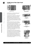
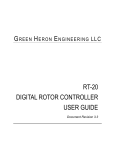
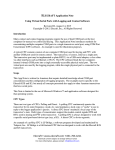
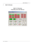
G R E E N H E R O N E N G I N E E R I N G LLC GREEN HERON EVERYWARE Version 2.3 AND GH WIRELESS CABLE USER GUIDE Document Revision 2.3 May 11, 2012 2012 Green Heron Engineering LLC 1107 Salt Road, Webster, NY 14580 Phone 585.217.9093 www.GreenHeronEngineering.com FCC Part 15 This product contains FCC ID: OUR-XBEE or OUR-XBEEPRO The enclosed device complies with Part 15 of the FCC Rules. Operation is subject to the following two conditions: (i.) this device may cause harmful interference and (ii.) this device must accept any interference received, including interference that may cause undesired operation. Industry Canada (IC) Contains Model Xbee Radio, IC: 4214A-XBEE or Model Xbee-PRO Radio, IC: 4214A-XBEEPRO RADIO AND TELEVISION INTERFERENCE This equipment has been tested and found to comply with the limits for a Class B digital device, pursuant to Part 15 of the FCC rules. These limits are designed to provide reasonable protection against harmful interference in a residential installation. This equipment generates, uses and can radiate radio frequency energy and, if not installed and used in accordance with the instructions, may cause harmful interference to radio communications. However, there is no guarantee that interference will not occur in a particular installation. If this equipment does cause harmful interference to radio or television reception, which can be determined by turning the equipment off and on, the user is encouraged to try to correct the interference by one or more of the following measures: Reorient or relocate the receiving antenna. Increase the separation between the equipment and the receiver. Connect the equipment into an outlet on a circuit different from that to which the receiver is connected. Consult the dealer or an experienced radio/TV technician for help. You may also find helpful the following booklet, prepared by the FCC: "How to Identify and Resolve Radio-TV Interference Problems." This booklet is available from the U.S. Government Printing Office, Washington D.C. 20402. Changes and Modifications not expressly approved by the manufacturer or registrant of this equipment can void your authority to operate this equipment under Federal Communications Commission’s rules. WARRANTY This product is warranted to be free of defects in materials and workmanship for 1 year. We will repair or replace, at our option, any equipment proven to be defective within the warranty period. All warranty work is F.O.B. Webster, NY, USA. This warranty is exclusive of abuse, misuse, accidental damage, acts of God or consequential damages, etc. Green Heron Engineering LLC liability shall not exceed the original purchase price of the equipment. TRADEMARKS Stackmatch is a trademark of Array Solutions COMTEK is a trademark of DX Engineering All other products, company names, brand names, and trademarks are the property of their respective owners. We suggest that you look over this document carefully. Section 1 is a brief overview of GH Everyware and the Wireless Features. Section 2 is a walkthrough tutorial for installation and operation of most features Section 3 will show you how to use the Sharing and Network Features Section 4 shows the details of the hardware configurations and installation connections Table of Contents 1.0 1.1 1.2 1.3 2.0 2.1 2.2 2.3 2.4 2.5 2.6 2.7 2.8 2.9 2.10 2.11 3.0 3.1 3.2 3.3 4.0 4.1 4.2 4.3 4.4 4.5 5.0 5.1 5.2 5.3 5.4 OVERVIEW THE SYSTEM COMPONENTS NETWORK DESCRIPTION AND CONFIGURATION ROTOR CONTROL INTEGRATION INSTALLATION AND QUICK START TUTORIAL INSTALL THE GH EVERYWARE BASE UNIT INSTALL THE “GH EVERYWARE SERVER” SOFTWARE SETUP A TEST REMOTE UNIT. CONFIGURE GH EVERYWARE SERVER DISPLAY OPTIONS AND FEATURES FOR RELAY DEVICES ADDITIONAL FEATURES FOR RELAY DEVICES GREEN HERON ROTORS WITH INTEGRATED STACK CONTROLS GREEN HERON ROTORS WITHOUT STACK CONTROLS OPERATING A ROTOR CONTROL EVERYWARE KNOB – ‘EK’ OTHER FEATURES AND NOTES SHARING CONTROLS AND NETWORK ACCESS 1 1 3 4 5 5 5 6 6 7 10 11 12 12 13 14 15 SYSTEM REQUIREMENTS INSTALLATION SETUP 15 15 15 HARDWARE REFERENCE 17 WIRELESS BASE WIRELESS BASE 8 RELAY OPTION MODULE WIRELESS BASE DIY OPTION MODULE WIRELESS REMOTE (WIO-8) LEDS TEST AND CONFIGURATION UTILITY – ADVANCED OPTIONS STANDARD SETTINGS MODULE TYPES SLEEP MODE ADDITIONAL FEATURES 17 17 19 19 22 23 23 23 24 24 APPENDIX A – N1MM CONFIGURATION 25 APPENDIX B – WIN-TEST CONFIGURATION 26 APPENDIX C – WIRING A STACK MATCH CONTROLLER 27 APPENDIX D – IP NETWORK CONSIDERATIONS 28 APPENDIX E – TROUBLESHOOTING 29 APPENDIX F – USB TO RS-232 STANDALONE APPLICATIONS 30 1 Section O V E R V I E W 1.0 Over view GH Everyware Wireless Cable is a distributed network solution to any station switching component that uses relays or manual switches. This can include antenna selection relays, directive antenna controls (4 square, 8 circle etc.) stacked antenna controllers, Beverage antenna switches, etc. The system can eliminate or reduce the use of control cables and control boxes, replacing them with a robust wireless (802.15.4) network and on-screen controls that you may customize for whatever relay control system you utilize. In addition, the system allows shared access through the use of standard IP (Internet Protocol) techniques. Any number of operator positions on separate computers, may share any or all of the switch and rotor devices under GH Everyware Wireless control AND they may also be utilized over the Internet. The system components are flexible and expandable to meet any station complexity requirement. Your existing antenna relays, stack controllers, 4 square controllers, transverter selection boxes (or any other device that uses relays) may be remotely operated and monitored from inside the shack, or anywhere in the world via the internet. At the same time, eliminating the control cables, eliminating the control box at the operating position and allow sharing of these devices among multiple operating positions or locations. GH Everyware also allows integration of RT20, and RT-21 rotator controllers into the systems either connected via separate COM/USB port, or even though the shared wireless link to the GHE Remote’s RS-232 port. If desired, you may use just Base Units (no wireless remotes) and gain all the benefits except the elimination of control cables from the shack. In this configuration of GH Everyware, you gain the computer and automated interfaces, shared and remote (Internet) access to up to 8 relays per GHE Base unit. This way, the wireless portion isn’t used, and all connections are made directly to the terminal block on the Base. A mix of wired, and wireless can also be utilized. The system can also support the ability to remote link any RS-232 serial device over a wireless link in a point-to-point fashion from your in-shack computer. GH Everyware Wireless Cable utilizes its USB connection at the base, and converts to RS-232 at the remote side. This allows you to use any RS-232 application that runs on your computer without the need for a native RS232 port, and connect to an RS-232 device anywhere within the wireless range. You may place your serial interfaced rotator control out at the base of a tower, remote your SteppIR controller (using 3rd party SteppIR Application), or control a remote transceiver that uses serial control. 1.1 The System Components The GH Everyware Server is a software program that runs on any computer(s) in your network. The Server manages shared access from the GHE Controller positions, and sends commands for desired actions to the remote devices. An integrated “Local Controller” is included that has on-screen operator controls for 1 O V E R V I E W each remote device under control. On-screen controls can be configured and customized by the user to many different configurations. GH Everyware Client is an optional software application that communicates with GH Everyware Server(s) over any IP network to allow shared or remote access to each device through the servers. It has the same user on -screen controls as the “Local Controller” part of GH Everyware Server. The GH Everyware Base is a hardware device that includes an 802.15.4 radio operating at up to 63 mw on 2.4 GHz. Connects to Server and is fully powered via USB, sends and receives wireless commands to GH Everyware Remotes up to 1 mile away. The Base may be optionally configured with 8 NPN or contact outputs for shack relay controls. Figure 1-1: GH Everyware Base The GH Everyware Remote is hardware device that includes an 802.15.4 radio that communicates with GHE Base. The Remote operates the end device relays and/or connects to a serial RS-232 device. Figure 1-2: GH Everyware Remote in Weatherproof Enclosure Figure 1-3: GH Everyware Remote PCB with Radio Module and Connectors ORDERING INFO: GHE Base The GHE Base includes USB cable and 1 mw standard range radio module with internal standard antenna. Indoor enclosure is included. Base Options: GHE DX 8 Relay IO DIY IO EXT ANT 63 mw extended range module Plug-in relay module with pluggable connector Plug-in connector module for NPN output or your own IO design External antenna connection, rear RPSMA 2 O V E R V I E W GHE Remote (WIO-8) Eight relay outputs plus serial port, 1 mw standard range radio module with internal standard antenna, and PCB level product for your own mounting. Includes industrial terminal block connectors for relay outputs, serial port and +12 VDC. GHE Remote Lite Same as Remote except has eight NPN Darlington driver outputs (Sink to Ground). Deletes relays and output terminal blocks. Remote Options: GHE DX 63 mw extended range module GHE ENC Weatherproof enclosure with cable entry for Remote or Lite GHE SC1 5’ Shielded Serial Cable for terminal block GHE SC2 3’ Ribbon Serial Cable for header 1.2 NETWORK DESCRIPTION and CONFIGURATION The GHE Wireless Network consists of a Server Computer connected via USB, to a GHE Wireless Base and one or more GHE Wireless Remotes. Each Remote only communicates with the Base unit, not between remotes. The Remotes are factory configured at Channel C and WIO Address of 1. This ensures that each remote as shipped, will communicate with a factory configured Base. (Which by our convention must always be Address 0) You must ensure that you do NOT use duplicate addresses in your installed system. You may assign addresses between 1 and 249 using the Test and Configuration Utility supplied with GH Everyware download. Note: The WIO Address, Channel number, and other settings are changed using the GHE Test/Configuration utility described in Section 5.0. Figure 1-4: Network Topology 3 O V E R V I E W More than one GHE Wireless Networks (another Base and set of Remotes) may be utilized on either the same computer Server, or on different Servers on the same computer network as desired. In order to avoid communication confusion, each additional wireless network should be set to a different RF Channel, of which 12 separate channels are available. The Channel numbers MUST be the same in all units on the same GHE Wireless Network. All units are shipped from the factory on the same default Channel ‘C’ unless specified differently. The Channels are easily changed in the field using the Test and Configuration Utility. The standard units have a 1 mw transmitter and a -90 dBm RX sensitivity. In many typical installations, this can yield acceptable results depending on the environment. The standard units are usually acceptable for room-to-room applications indoors, where little attenuation might exist in walls and other indoor obstructions. Outdoors, up to 100’ or more can be realized if the units are in LOS (Line-of-Sight) of each other. The extended range units use 63 mw of output power and have more sensitive receivers that can communicate down to -100 dBm. They are capable of traversing from an indoor Base unit, outdoors and up to a few hundred feet away. Even more range can be experienced by careful placement of Base and Remote units to avoid lossy obstructions and to obtain close to LOS conditions. Using external antennas, ranges of 1 mile are possible. Some windows can be quite lossy because the same technology that limits IR radiation can limit 2.4 GHz RF as well. Mounting a base just outside the window can have a dramatic effect on range. Standard USB extensions are available to allow this sort of installation. The on-board LEDs allow easy range testing and mounting experimentation of your units. In general, mount your units with as close to LOS conditions as you can, maintain clearance from large metal and other RF blocking objects like reinforced concrete walls and foil backed insulation. If you require more range, the Base may be easily configured with external antenna option, increasing the range of both ends. As special order, GH can also provide Remote modules that support external antennas for custom installations that require even more range. If you have a Base that must communicate with a Remote in the next room as well as a Remote that is located outside at the tower, it is OK to use a standard range module as the indoor Remote, and Extended range units for the others 1.3 ROTOR CONTROL INTEGRATION When using Green Heron Rotor Controllers in conjunction with a Yagi Stack Controller (e.g. Array Solutions Stack Match® / Master), the controls for the rotors and the Stack Controller are integrated into one on-screen control that is simple and easy to operate. At the same time, eliminating all the clutter of the stack boxes, rotor controller boxes (at the operating position), and allow multiple operator positions to share these controls. 4 I N S T A L L A T I O N A N D Q U I C K S T A R T T U T O R I A L 2 Section 2.0 Installation and Quick Star t Tutorial 2.1 Install the GH Everyware Base Unit 1. Connect the Base Unit into an available USB Port on a computer that will be running your Server. You may find that the required drivers are already loaded and nothing much will happen except you will get a new USB Serial Port show up in Device Manager. Make a note of the COM number that is assigned. If you are using an external USB hub, please ensure that you use the hub’s additional power module. The Base unit will require more than the 100ma that may be sourced out of an unpowered USB hub. 2. If the drivers are not already loaded, you will get “New Hardware Found, USB UART” and New Hardware Wizard will appear on your screen. The exact procedure will vary for different versions of Windows, but in general, the sequence is the same. All versions of Windows contain the FTDI drivers that are needed, either within the original install, or from Windows Update. If for some reason, you can’t locate the correct drivers on your system, they are provided in the .zip file download for the current GH Everyware release on our website. The drivers are in the folder named “CDM 2.04.06 WHQL”. 3. Follow the directions and load both the “ftdibus” and following that, the “ftdiport” drivers. 4. After installation is complete, verify the COM port using Device Manager. Simply unplug and plug in the Base Unit while watching Device Manager COM ports to see what port is assigned. Note the COM Number. Note: The COM port number will remain constant whenever you plug this specific Base Unit into any USB port on this computer. 2.2 Install the “GH Everyware Server” Software System Requirements: Windows XP SP2, Windows Vista, Windows 7 Java Runtime Environment version 6 (JRE 1.6) Windows .NET environment version 3.0 or higher 5 I N S T A L L A T I O N A N D Q U I C K S T A R T T U T O R I A L 1. If the user has Administrator’s privileges, double-click the “GH Everyware Server.msi” installation file. If not, right-click the installation file and choose to run as Administrator. 2. Follow the onscreen directions. In most cases the defaults will be sufficient. 3. If you do not have a recent enough version of the Java Runtime Environment, the installer will prompt you to download it. 2.3 Setup a test Remote Unit. 1. Connect a remote unit up to a suitable 12 VDC power supply (See 4.2.1) and set the remote on your table. A 9V battery is a quick and easy temporary power supply. 2. For initial testing, we will have the Base Unit, the Server Computer and Remote Unit all within easy viewing and access. Ensure that the CHANNEL number on both the Base and Remote are the same, and then note the ADDRESS number on the remote unit. 2.4 Configure GH Everyware Server We will be configuring GH Everyware Server to work with our test Remote Unit. The process will walk you through the basic steps of installing and using GH Everyware Wireless Cable as a remote relay switching device controlled by your computer. 1. Start GH Everyware Server by double clicking on the Program Icon, or selecting from the Start Menu. “Server Started” will appear in the message window. Figure 2-1: Server Main Window 2. Select SettingsDevice Manager from the menu bar. Create an entry on the first line for your Remote Unit: Give it a name like “Test Switch” Select the COM port for the Base Unit from section 2.1 Select Device Type “WIO 8”. Subtype “6-Way Switch”. Set WIO Addr to the ADDRESS number for the Remote Unit. Note: WIO Addr “0” is reserved for the local connected Base Module. Outputs from this module can be made available by the addition of a few components as detailed in Section 4.4. The Base Unit is limited to supplying and NPN transistor to ground for relay operation. You may use external circuits or relays if you need to convert this to +V or contact closures. 6 I N S T A L L A T I O N A N D Q U I C K S T A R T T U T O R I A L 3. Click on the button labeled Disconnect to attempt Connect to your Device If all is well, the button will change to Connect Status and your Remote Unit will light up its LED light bar for RSSI (Signal Strength) indicating CONNECT to Server. 4. Close the Device Manager Window and select SettingsLaunch Local Controller. Your screen will now show the default control for the predefined 6-way antenna switch. By clicking on the various buttons, you can change the relay selection as desired. You can hear the relays changing as you do this. Note: If your unit is a Lite Remote, you will need to connect up a target remote relay device of some sort in order to hear relays. This on-screen control is best suited for antenna switches that do not contain many directional options. Each button and its name are separate selections from a typical 6 position coax switch. Figure 2-2: Button Switch Control This control can be modified to suit many different needs. Notice that the title bar of the control shows an RSSI value. This is the wireless device signal strength that the Remote Unit is reporting back as to how well it is receiving signal from the Base Unit. (See section 4.1 for more RSSI information) 2.5 Display Options and features for Relay Devices Let’s now add a HOTKEY to this control. A HOTKEY will allow you to change your remote switch without having to use the mouse to gain focus. You will assign keys on your keyboard that will (for this exercise) rotate forward through the list of positions on your 6-way relay. Right click on the Switch Name portion (“Test Switch”) and then left click on “Assign keystroke to cycle forward”. Now tap F12. From now on, whenever this control is on-screen, pressing F12 will select the next position (down) on your 6-way relay. You may assign keys for forward and backwards as well as for each individual (or a single favorite selection, right click on the individual button to assign a HOTKEY for that button. Note: Only numeric keypad, special application, function and c ombination keys using <Shift>, <Ctrl> and/or <Alt> are allowed to be assigned to these HOTKEY functions. You must make sure you don’t assign something that will be needed by another program running at the same time on your computer. 7 I N S T A L L A T I O N A N D Q U I C K S T A R T T U T O R I A L Graphic Switch Control Display: A COMTEK® 4 Square is a directional antenna switch, we will use a different way to display it on the screen using a graphic or “map” image with a color directional indicator. On the GH Everyware Server message window, Select: SettingsDevice Manager Click on the “Connected” button to disconnect the device. Now change the Subtype for our test device to “Comtek 4 Square” and click on Disconnected in order to re-connect back to our remote unit. Our display now shows a simple graphic directional display depicting our control for the 4 Square using the default compass rose Figure 2-3: Map Switch Control background image. You can simply click on a direction area or assign HOTKEYS to positions, or cycles as with the button control by using the Right Click menu. Other Background Image: You can add custom maps or other images to your control. Many web based sites will let you create projections based on your QTH for use in these controls. Right click again on the 4 Square control and select “Set custom back ground Image” and browse. Re-size the window for best viewing as desired. The image types supported are JPG, GIF and PNG. We’ve now seen two of the three types of Switch Controls that you can make using GH Everyware. Now we will use the Wireless IO Edit or (WIO Editor) to see how we can customize a Map Control to meet our exact needs. WIO Profile Go to Device Manager and select EditWio Profile Editor. Next select FileOpen and open up the ComTek 4 Square Switch profile from the list. Figure 2-4: WIO Profile Editor You can see that here is where the display type is selected, Map in this case, for this control and the name of each position. 8 I N S T A L L A T I O N A N D Q U I C K S T A R T T U T O R I A L The Heading Degrees and Beamwidth select the direction and width of the color beam display on the map. Checking Bi-Direction includes the beam that is 180 degrees away from the specified Heading. Outputs select which relay or relays are used for each position of the control. The output choices are: N/C (no change) – The state of this bit is not changed for this position ON – This bit is on, or relay is picked OFF – This bit is off, or relay is dropped MOM – This bit is turned on for ½ second (momentary), then back off It should be obvious that the profile can be changed to depict any possibility of relay control devices up to eight output selections. With additional logic, one could easily go well beyond 8 relay positions by using BCD encoding of outputs. Notice that the 4 Square has 4 positions, but uses only two output relay lines. Note: The N/C is used to allow more than 1 switching device to share a single Remote Unit using different bits or outputs. All outputs used for a single device MUST be ON, OFF or MOM. The use of N/C is ONLY for bits that are used in another profile that is used with the same remote. N/C defines those bits that should NOT be changed when operating this control. Band Switch Control The final Switch Control we will use is very similar to the first “Button Control” as it uses Buttons for selection, but this one also can be automatically or manually selected via the current BAND information obtained from other applications running on the same computer. Let’s make one now by modifying the 6-Way Switch control into a Band Switch. Go to Device Manager and select EditWio Profile Editor. Next select FileOpen and open up the 6-Way Switch profile from the list. Change the Device Type to “Band Switch and click the Band Switch Radio Button. Now edit the position Names to read positions 1 through 6 as 160 through 10 Meters, and enter the frequencies you wish to use as the criteria for each specific switch position. Your profile should look similar to Figure 2-5 below Figure 2-5: WIO Profile Band Switch 9 I N S T A L L A T I O N A N D Q U I C K S T A R T T U T O R I A L Click DONE and go ahead and save this new profile. It will take the name of the Device Type as its first choice. Now DISCONNECT the WIO Device in Device Manager, change the Device Name to “Band Switch”, then select WIO Subtype drop down and see that your new Band Switch is a new option. Select it and CONNECT. Now, your Switch Control will be your new Band Switch that you just made and should look like Figure 2-7: Controller Menu Bar W/O rotors. Note: Using two of these Band Switches will create the controls for a wireless 6-PAK system. One Control could be “RUN1”, the other “RUN 2” for setup as an M/2 or SO2R operation. Each of the two controls can be operated from different computers on your network and eliminate the 6PAK control box, it’s tethered cables and allow the two stations to be physically separated from each other.. 2.6 Additional features for Relay Devices When only relay devices are utilized (no rotors), there is a blank window that contains an additional Menu Bar. These selections under Configuration and Bands allow additional ways to control your displays, including the automatic Band Selection for Band Switches. Select: ConfigurationSwitchesSwitch bands Place a check mark in the bands on which you wish to have that switch device available. You may have more than one device on a band, and more than one band per device. You may choose to view only HF contest bands, all HF bands, or VHF-microwave bands by selecting the appropriate item at the bottom of the window. Other items in the Configuration menu enable selection boxes on map displays, change the sizes of the controls, view all of the current hotkey assignments or clear them all, setup software control or reset all settings back to default. Figure 2-6: Band Switch Control Select: ConfigurationBand This selection sets the current band selection criteria. Automatic band selection is currently only available in conjunction with N1MM Logger or WinTest software. Other methods will come soon. See Appendix A for N1MM and Win-Test detailed setup information Figure 2-7: Controller Menu Bar W/O rotors Note: Some devices may want to be enabled for all bands, some for only one, two or three depending on the use. Check the appropriate band boxes in Switch bands for each display control. 10 I N S T A L L A T I O N 2.7 A N D Q U I C K S T A R T T U T O R I A L Green Heron Rotors with integrated Stack Controls Note: In order to try this out as described here, you will need at least one RT-20 or RT21 controlled rotor to connect up to your server in order to get a rotor to really turn. For other rotor types, or for testing, you may use “Fixed Antenna” for each antenna on the Stack Match in order to get the LED Selected Stack Control shown here. The Stack Match Subtype is used designed for the integration of rotors and Stack Match as described in this section, but can be used with manually controlled rotor controllers. When GH controllers (RT-20, 21) are utilized, we can add additional sophisticated controls that can automate direction pointing as well as integrate Stack Match (or other Stack Controls) within the same operator User Interface Control. Figure 2-8: Stack Match Device Manager Example The figure above shows a Device Manager setup for a three stack of Yagis where two are rotatable and the third is fixed in a specific direction. In this example, the top rotator is connected directly to a serial port (COM 20) on the Server computer, while the bottom antenna rotator controller is using the serial port on a Wireless Remote Unit. The same Remote Unit is being used for a Stack Match. (Base on COM 19, WIO Address of 1) In order for the stack to indicate which antennas are being selected, the Name field, for the Stack Match Subtype entry, must contain the names of the three rotators (antennas) that are connected to that Stack Match. The Device Type for the non-rotatable antenna is “Fixed Antenna”. “Cloned Antenna” is used when there are two or more antennas on the same rotator/mast and therefore, turn as one. Note: The “Name” used for the Stack Match example above is “TOP 10,Bottom 10,SOUTH 10”. This window is actually an expansion of the Control window described in 2.6 except the window now shows our Rotors with the integrated Stack Control. Figure 2-9: GH Everyware Controller with Rotors and Stack Control 11 I N S T A L L A T I O N 2.8 A N D Q U I C K S T A R T T U T O R I A L Green Heron Rotors without Stack Controls If your requirement is only control and sharing of GH Rotor controls (you wish to use normal manual controls for stacks, or don’t need them), the setup would be the same except you eliminate the Stack Match entry in Device Manager. Rotors may still be connected directly to your server, or via GH Everyware Wireless (or combination) as desired. Note: If you are using GH Everyware ONLY for control of rotors that are directly connected to Servers, you do not need to use or configure any GH Everyware Wireless Devices. You still have sharing and internet access to rotors when used with only Server connected rotors. 2.9 Operating a Rotor Control Turn button: Enter a heading from 0 to 360 degrees in the heading box. Then press the turn button. The rotor will automatically start turning to that heading. You can press the stop button to stop it before it arrives at the new heading. Preset Location: Right clicking either the rotor name or the heading display will display a pop-up menu of preset locations. To enter preset locations chose “Edit Presets” from the Configuration menu. In the dialog box, enter a name for the preset and its heading in degrees. Press OK to save your changes. Computer Control: Integration with logging software for control is possible currently with N1MM. Others to come. See Appendix A for N1MM setup and integration. Turning multiple rotors together Each rotor in the main control window has a checkbox on the far left. Placing checkmarks causes all rotors to share the same commands, effectively tying them together as one single rotor. If the user tells a checked rotor to turn to 45 degrees, all checked rotors will turn to 45 degrees. Similarly, if the user tells a checked rotor to stop, all checked rotors will be told to stop. Note: This only applies to rotors that are checked and visible. Checked rotors on other bands that are not visible in the current display will not respond to manual or external software commands. Rotor Bands: On the GH Everyware window Select: 12 ConfigurationRotorsRotor bands I N S T A L L A T I O N A N D Q U I C K S T A R T T U T O R I A L Rotor bands allow filtering of rotor devices just like Switch bands filter switch devices as described in Section 2.6. There is an extra column in the dialog for selecting the order in which you wish the rotors to appear. The order can be any integer number, and lowest numbers appear at the top of list in the main control window. The order numbers do not need to be consecutive, but two rotors cannot share the same order number. When you connect to a rotor for Figure 2-10: Rotor Bands the first time it will be assigned a random order number between 100 and 500. You can click on any column to sort the rotors by that column Changing the Band When in manual mode the band can be changed from the “Band” menu in the main controller window. The list of bands is tied to the rotor configuration dialog. Selecting “All” will show all available rotors. Stack Control The Green “LED” are the Stack Control. Green means this antenna is selected. You de-select by double clicking on an LED. Stack Matches are better controlled via HOTKEYs and these are done the same was as we assigned them for switches. Right Click on the LED, and Left Click on the desired HOTKEY function, then type the key to use for that function. Hovering will show what keys are currently in use, and report on RSSI if this unit is connected via a GHE Wireless Device. Note: You cannot turn all rotors off on a Stack Match. “No antenna selected” is not a valid switch position with this device. Note: The Stack Match (1-4) and (5-8) controls are pre-defined profiles that cannot be modified by users. It is a Subtype selection in device manager, but there is no WIO profile editor for it. Contact GH Engineering if you need additional Stack Controller types defined. See Appendix B for Stack Match relay assignments for wiring into your Stack Match relay box. 2.10 Everyware Knob – ‘EK’ For those applications where a physical rotary control is desired, the optional GH ‘EK’ may be best solution. EK is a USB device that plugs into the user computer to act as a physical rotary switch for any of you on-screen controls. You may use it to rotate a button, map or band switch through its selections, set headings for an RT-21 rotator, or select from your rotator presets. Installation 13 I N S T A L L A T I O N A N D Q U I C K S T A R T T U T O R I A L The software driver installation is part of the normal GH Everyware software so there should be no extra steps involved. Your computer will recognize the EK as an “input device” and install it automatically. You select which device you want to control by pressing and holding the EK down for about 2 seconds. Turn the knob to select the onscreen control you wish to use it with, then release the knob. You may change the desired control to use with a particular EK by repeating the press and hold at any time. You may use multiple EK, the connected EK address is displayed in the title bar on a device when it is attached. Switch Devices Turn to select switch position Tap to select ‘home’ position (first position in the WIO profile list) Rotator Devices You may use EK to change the heading in the rotator window You may use EK to select from the list of presets Tap the EK to initiate the rotator motion 2.11 Other Features and Notes 1. The 8 output bits of a single base or remote may be shared among different switch controls. E.g. You can use 6 bits for a coax switch, and 2 bits for a 4 Square. 2. Outputs may be configured as MOMentary in device manager for operating latching relay devices or on/off momentary devices. Connecting an ON/OFF bank to a larger relay to control an AC circuit is very useful for many applications. 3. Added in version 2.3 is an additional Device Type in the WIO profile manager called “On/Off Bank”. This allows implementation of a group of on/off buttons 4. You may display and use rotator “Presets” for each rotator device you have configured, OR you may select “Rotors -> Show Global Presets” in the Client, and show only one set of Presets that will operate all rotators that are both onscreen, and have a check mark in the first column. 5. In Client, software control from N1MM and WInTest better supports SO2R by allowing rotors and switches to be displayed for the band from both radios (or VFOs) at the same time. You may select from either radio in an SO2R system, or both. 6. You may connect a TX keyine (gnd to TX) to the front PTT jack on any Base unit. Whenever this jack is grounded, all switching on that Base, and any connected Remotes will be disabled to prevent hot switching. When PTT goes high, any switch commands that were issued will be executed. 14 S H A R I N G C O N T R O L S A N D N E T W O R K 3 Section A C C E S S 3.0 Sharing Controls and Network Access In order to share switch and rotor controls among multiple users, remote the user away from the Server, or add internet access to your controls and devices we must use the optional GH Everyware Client software on each the user’s computer. This software nearly identical to the Server’s Local Controller with the addition of supporting TCP/IP Connections to GH Everyware Server. In addition, GH Everyware Client can interface rotor controls to hardware terminal servers as an option. The Local Controller in GH Everyware Server is automatically connected to the Server on that same computer. GH Everyware Client must be configured to connect to each Server. This also means that the controls utilized at any one time by a user of GH Everyware Client may be spread across multiple Servers. The servers may be located on the same local network, or anywhere in the world via the Internet. 3.1 System Requirements 1. 2. 3. 4. 5. Windows XP SP2®, Windows Vista® Java Runtime Environment version 6 (JRE 1.6) Ethernet card or Wi-Fi connection Windows .NET Framework version 3.0 or higher Supported Logging/Radio control program if desired 3.2 Installation 1. If the user has Administrator’s privileges, double-click the “GH Everyware Client.msi” installation file. If not, right-click the installation file and choose to run as Administrator. 2. Follow the onscreen directions. In most cases the defaults will be sufficient. 3. If you do not have a recent enough version of the Java Runtime Environment, the installer will prompt you to download it. 3.3 Setup 1. Start the program either from the Start menu or by double-clicking the GH Everyware Client shortcut if you asked for one during installation. This will display the main control window: 2. Connect to servers: Select: ConfigurationServers 15 Figure 3-1: Main window for GH Everyware Client S H A R I N G C O N T R O L S A N D N E T W O R K A C C E S S Figure 3-2: Server Dialog in GH Everyware Client GH Everyware Server: Choose “GH Server” from Server Type box Enter IP address (e.g., 192.168.1.80) or hostname. To connect to GH Server running on the same computer as the controller software, enter either “127.0.0.1” or “localhost”. Enter TCP/IP port on which the server is listening (e.g., 10000) Enter username and password if the server has authentication enabled. You do not need to supply a name for the rotor or device because GH Everyware Server reports the names of the rotors that reside on it. If you are using a hardware Terminal Server (Lantronix® or similar) for rotor(s): Choose “Terminal Server (TCP)” from Server Type box Enter IP address (e.g., 192.168.0.8) or hostname Enter TCP/IP port on which the server is listening (e.g., 10000) Supply a name for the rotor. Press the “Disconnected” button at the far right of the server window. This will start the connection process. If the controller is able to establish a connection to the remote machine the button will show “connected” and a green LED. All available devices that are configured on that server should be visible in main controller window. If the controller is unable to establish a connection, go to the troubleshooting section Appendix D for some common solutions. Note: You may show all devices on each server, or show only those devices that are available on certain bands by using the Band Filters as described in section 2.6. Note: You may connect to as many as 10 Servers at once. The servers may be located within your local network, or external as desired. All the various options and settings that are used in the local controller (as described in section 2.6) also apply to GH Everyware Client. Carefully review the information in Appendix D for Network considerations, other options and security features. 16 H A R D W A R E 4 Section R E F E R E N C E 4.0 Hardware Reference 4.1 Wireless Base There are no configuration jumpers on the Base Unit main board. Connection to the Server is made through the front panel USB port. The PTT RCA Jack may be paralleled with any ground-to-transmit keyline. When PTT is grounded, the Base unit will disable all local and remote switching activity to provide protection from hot switching relays associated with that specific Server port. The two red LED indicators show RX and TX activity on the USB Bus. (Note that this does not necessarily indicate TX and RX activity over the wireless link.) There are 4 LEDs that indicate RSSI (signal strength) of the last receive packet message. The number of LEDs lit indicates how strong the last packet was: # of Lit LED(s) 1 LED/Yellow 2 LED/Green RSSI of last packet Receive Data Threshold +10 dB fade margin 3 LED/Green +20 dB fade margin 4 LED/Green +30 dB fade margin The Standard Range (1 mw) module and the DX Range (63 mw) module have slightly different receive thresholds. The LEDs indicate the correct amount of fade margin (signal level above threshold) for each module. Because the GH Wireless modules provide retry at two levels of operation, 1 LED may be enough signal to operate reliably. BUT we recommend that you get at least 2 LED to light most of the time. 4.2 Wireless Base 8 Relay Option Module With the optional 8 relay module installed, the Base can operate up to 8 relays directly connected without actually using a wireless link. Since the Base is USB powered, the module cannot source 12V, but it can be configured so that each pair of relays can either switch to ground, or to a common supply that you provide on the COM terminal of the connector block. The relays can switch up to 1A @ 30VDC, or 1/2A @ 115 VAC. The 8th relay may be configured as an N/C contact if desired. The drawings show the jumper and connection options. 17 H A R D W A R E R E F E R E N C E Figure 4-1: 8 Relay Option Module Figure 4-2: 8 Relay Option Module Schematic 18 H A R D W A R E 4.3 R E F E R E N C E Wireless Base DIY Option Module The DIY (Do It Yourself) module provides a convenient way to add connections to your base that either use the NPN outputs directly OR for cases where you want to provide your own relays or other circuitry based on the NPN outputs provided by the Base unit. The board provides access to the NPN outputs that may be jumpered to appropriate connector terminals on the board. OR there is a .1” grid to mount your own components as desired. +5 and 3.3V and ground areas are all provided. Be aware that the overall 5V current capacity provided by this bus powered USB device is 500ma. (The “INPUT” connections are for future GH Everyware functionality that will provide for analog or digital input capability to be provided in a future release. Figure 4-3: DIY Option Module 4.4 Wireless Remote (WIO-8) Each GHE Wireless remote can be configured to run a serial port extension, and/or relay control boxes of up to 8 separate relays. If you are using the serial port for a Green Heron Rotor controller, then you may use one Remote Unit to do both the serial port and a relay controller at the same time. (GH rotor controllers do not have to be connected remotely through the Remote Unit in order to have shared access, they may be direct connected to any server computer also.) For serial devices that are not interfaced through GH Everyware and therefore must use some third party application (Like a Transceiver serial interface, or a StepIR controller) you will have separate Base and Remote Unit on a Channel by themselves for link. In this case, GH Everyware software is not utilized, (See Appendix F) 19 H A R D W A R E R E F E R E N C E Figure 4-4: Remote Unit Configuration The Remote Unit has different ways to connect power, serial links, and relay controls so that you may use the method that makes most sense in your application. This section will help you understand all the options and settings that are available. 4.4.1 POWER CONNECTION The remote unit requires a nominal 12 VDC for proper operation with its internal 12 VDC relays. The “Lite” version of the Remote board has no relays and has a significantly relaxed voltage requirement. We Suggest: 9 to 16 VDC for the Standard Board 5 to 24 VDC for the “Lite Board” You may connect the nominal 12 VDC to one of two connection points: 1. J1 Green Power Connector 2. J4 Output Header Pin 9 (+) and Pin 10 (-) The GHE Remote has 1A internal automatic resettable Polyfuse. This fuse is in series with the J1 Power Connector and will protect (or limit) the current that can be drawn from the J4 10 pin header. If you connect power input for the GHE Remote from the J4 Header, the fuse will NOT be in the circuit and will not protect the GHE Remote. 20 H A R D W A R E R E F E R E N C E 4.4.2 Current Requirements (typical @ 12 VDC) Idle Connected Connected Connected Connected Connected Relays - 0 Relays - 1 Relays - 2 Relays - 4 Relays - 8 60 mA 105 mA 120 mA 135 mA 165 mA 220 mA Does not include current for external device/external relays Add 5 mA for DX Modules Lite Modules do not have internal relays, Use only 1st two columns 4.4.3 SERIAL (RS-232) CONNECTION The RS-232 connection is a simple three wire connection not supporting or requiring any handshaking for operation. The connection may be made by either of two connection methods: 1. J2, the 3 terminal green screw connector (Pin numbers match the equivalent DB9) 2. The 10 pin SERIAL header. The Pin numbers are such that a 9 conductor flat ribbon cable will connect 1 to 1 with a DB9 standard pinout. (Order GHE SC-2) Two Jumpers labeled DCE (P7 and P8) are provided to reverse the TX and RX connections depending on the serial application. With the Jumpers in DCE position (2-3) , The board acts as a DCE device and will directly connect with a DTE device like a computer. With the jumpers in the DTE position (1-2), the board acts as a DTE device and will directly connect with a DCE device like a radio or rotor controller. 4.4.4 OUTPUT RELAY CONNECTIONS Signal J3 Term Block J4 Header Out 1 1 1 Out 2 2 2 Out 3 3 3 Out 4 4 4 Out 5 5 5 Out 6 6 6 Out 7 7 7 Out 8 8 8 +12VDC 9 Ground 10 Note: Out 1 through Out 8 are the relay outputs as defined in Device Manager for the connected Remote Unit There are multiple arrangements and connection methods for interfacing the GHE Wireless Remote to relay systems Standard Module (w/relays) The standard module uses relay outputs for the external switching needs. The relays are rated at: . Max. operating voltage 125 VAC, 60 VDC 21 H A R D W A R E R E F E R E N C E Max. operating current 1 A Max. switching capacity 62.50 VA, 30W Jumpers #1 through #8are used to select whether each individual relay output is GND, or the nominal 12VDC routed to J3 and J4. Like the Lite Module, either J3 or J4 may be used and the standard module provides a green screw terminal interface on J3, with the 8 pin header on J4. See the table above for the terminal assignments. Lite Module The Lite module contains no relays, but does provide NPN Darlington drivers for sinking each of the 8 relay outputs to ground. The outputs are rated at 50 VDC, and 500 ma of collector current. Total device dissipation of 2.25W The Lite module contains has an 8 pin output header J4 that may also be used to provide power to the module. Optionally, the Connector at J3 may be used. 4.5 LEDS The Remote board contains diagnostic LEDs indicating: Power – Red RSSI – 1 through 4 green or LED Light Bar indicating signal strength of the Base Unit when the Server device is connected, or trying to connect. (See section 4.1) 22 T E S T & C O N F I G R U A T I O N U T I L I T Y – A D V A N C E D O P T I O N S 5 Section 5.0 Test and Configuration Utility – Advanced Options 5.1 Standard Settings The Test and Configuration program allows you to make configuration changes to the Base or Remote radio module that is contained inside each GH Everyware Unit. This will allow you to quickly change the Network Settings including the Channel Letter and Address number. You can also change the device type assigned to the module. This program communicates through the device USB or RS-232 port as needed. 5.2 Install and Connect. – Install the program by browsing to the Test and Config directory contained on the CD, then run the SETUP program. Plug in the Unit’s USB cable before starting the program each time to ensure that SETUP will find the module’s COM port OK. Select the COM port and press CONNECT. A Status message and the connect speed will be shown in the Status Line, the program will advance to the Standard Settings Tab. NOW, click on the READ button to read the current module settings. Network Channel, Address and Baud. – You may change the Channel and Address, and Write the settings back to the module. Also, the baud rate assigned to the serial port can be changed to match a serial device that you may wish to connect. For GH Rotor Controllers, this is typically 4800 baud. Remember that each Remote Unit must have a unique Address AND the Channel Letter must match that of the Base. The Address field may be grayed out or filled in according the Module Device Type. E.g. If you are programming a GHE Base, the Address MUST be set to “0”. The GH Everyware Server must connect to a GHE Module at 9600 baud, so this is the default setting for all modules. Module Types GHE Base – Used as the master radio in a GHE network with one or more Remotes. The GHE Base MUST be used with GH Everyware software for control. Unit Address is “0” GHE Remote – Used as a remote radio in a GHE network communicating with a single Base with the same Network Channel Letter. Each remote on a network must have a unique Address between “1” and “249”. PTP Base – Used as the computer end of a Point-to-Point serial link. GH Everyware is NOT used as the controlling software. The Address of a PTP Base must be “0”. PTP Remote – Used as the remote end of a Point-to-Point serial link. The Address of a PTP Remote MUST be “250” 23 T E S T & C O N F I G R U A T I O N 5.3 Sleep Mode U T I L I T Y – A D V A N C E D O P T I O N S GH Everyware Remote units may optionally be enabled for battery operation where current consumption must be managed. Use the Standard Settings Tab -> Sleep Time value to configure the amount of time that the module will stay asleep in the absence of any network activity. Since GH Everyware communicates with each Remote Unit about every second, we wake up each module that is in Sleep Mode and stay awake for two seconds to see if the Base Unit is communicating. If it is, the Remote will stay awake for another two seconds. If nothing is heard in two seconds, the Remote will sleep for “Sleep Time” seconds. When asleep, the module will draw just a few ma vs. ~ 100ma when awake. By measuring the normal current (exact value will be dependent on how many relays and external relays are picked) you can estimate the average current by: (2 / SleepTime) x Normal Current = Average Current Note: Any relays that were picked when the module goes to sleep will remain energized. If you don’t need the relays picked when using Sleep Modes (GHE Server disconnected) then you should create an OFF position in your device profile. Note: You can reduce the consumption further by removing the Link and/or POWER LED from the Remote unit, or changing the series resistors (R7, R18) to higher values. 5.4 Additional Features The other tabs and buttons that don’t appear to do anything yet are intended for future releases. 24 A P P E N D I X A – N 1 M M C O N F I G U R A T I O N APPENDIX A – N1MM CONFIGURATION You must configure N1MM to send radio and rotor information over the network. You can do this by editing the N1MM Logger.ini file so that it broadcasts radio and rotor data. This is entered below the “[ExternalBroadcast]” tag. An example is given below. [ExternalBroadcast] IsStartRotorProgram=False DestinationPort=12060 DestinationIPs=127.0.0.1 IsBroadcastRadio=True IsBroadcastRotorCommands=True *** If Getscores is used, it will interfere with the Destination IP for the local machine. In this case, add the real IP of the local computer (192.168.1.104 for example) in the DestinationIPs like this: DestinationIPs=127.0.0.1 192.168.1.104 N1MM will send the radio data to the local computer (127.0.0.1) on port 12060. If have two computers available at the operating position, it is possible to put GH Everyware Controller on a separate computer from N1MM. Just replace DestinationIPs with the address of the computer on which GH Everyware Controller is installed. You also must set the port on which N1MM sends rotor data. To use GH Everyware Controller you will want all rotor commands to appear on the same UDP port regardless of what band the antenna is on. You should configure your antennas so that all frequencies are on the same port. You can do this by entering every band on a single line and choosing a single port number. You should choose a port number that is NOT valid COM port on your system. This will keep N1MM from sending rotor data to any serial device that is connected to your computer. Also take note of the “starting port” at the bottom of the configuration window Once you have chosen a port number you must tell GH Everyware Controller what port numbers to listen on for rotor and radio data. You should set the rotor port to N1MM’s staring port + the port number of the rotors. For example, if N1MM’s starting port is 12040 (the default) and I set all bands to port 10, I should configure GH Everyware to listen on port 12050. To receive the radio commands, set the radio port to the DestinationPort value in N1MM Logger.ini, or 12060 (the default value) if none is specified. Dialog for N1MM port configuration in GH Everyware Controller 25 A P P E N D I X B – W I N - T E S T C O N F I G U R A T I O N Appendix B – WIN-Test Configuration Win-Test’s WT Rotors is somewhat similar in functionality to GHE Rotor Controls EXCEPT it will not integrate in the Stack Controls, or provide as many nice operator features for touch screen, or presets, or graphic displays etc. If you use a mix of rotator controllers, and/or want the Band Switch controls in GH Everyware to be available, you can config GH Everyware to use the WinTest broadcasts. They can co-exist along with WT-Rotors if desired. You will configure Win-Test as you would for WT-Rotors. Then using GH Everyware Controller>Configuration ->Software Control ->Win-Test Setup: Set UDP Port to match the same Rotor Port in Win-Test Select the Broadcast IP Address. o If you have configured Win-Test to broadcast to local network, and your IP Addresses are in the 192.168 range, select Local Network o If Win-Test is configured to broadcast loopback, select loopback. o If you have Win-Test broadcasting to the local network and you have a network IP range of other than 192.x.x.x, and then select “Custom binding address and supply the IP for it. Check/configure “Listen for Station Name” for multi-environments to filter stations. To limit responses to this controller from wrong stations’ broadcasts. This is same setup as in WT Rotors. Rotors/Switches Follow – for following bands on Active, or specific Radio. 26 A P P E N D I X C – W I R I N G A S T A C K M A T C H C O N T R O L L E R APPENDIX C – Wiring a Stack Match Controller Stack Match relay boxes use 4 relays and require +12V to each with a single return. This example will supply 12 VDC from the GHE Remote Unit (standard unit with relays) which in turn has its 12V source to power the Remote Unit connected via J1). The first table is for a device configured for bits 1-4, the 2nd table is for bits 5-8. Device – Stack Match (1-4) Place jumpers #1 through #4 in the 12V position (Section 4.2) Connect the Stack Match to J3 or J4 as shown in the table. GHE Remote Out 1 Out 2 J3 terminal 1 2 J4 Pin 1 2 Stack Match IN 3 Out 3 3 3 2 Out 4 4 4 1 9 10 N/C GND +VDC in/out GND in/out Device – Stack Match (5-8) Place jumpers #5 through #8 in the 12V position (Section 4.2) Connect the Stack Match to J3 or J4 as shown in the table. GHE Remote Out 1 Out 2 J3 Terminal 5 6 J4 Pin 5 6 Stack Match IN 3 Out 3 7 7 2 Out 4 8 8 1 +VDC in/out 9 N/C GND in/out 10 GND 27 A P P E N D I X D – I P N E T W O R K C O N S I D E R A T I O N S APPENDIX D – IP Network Considerations IP Addresses For local networks (no internet) you may use either Static or DHCP IP addressing. If you use DHCP, then the IP address references in GHE Controller MUST be by computer name. For Internet access, you will have to enable port forwarding in your router and these typically support only IP address (not names) so you MUST use Static IP address on your Server Computers. Port Numbers - GH Everyware Server SettingsSet port You should use port numbers of 10000 or higher in order not to conflict with existing standards. Each GHE Server MUST have a unique port number. GHE Controller will then be setup to connect using the IP (or name) and the Port Numbers that you assigned to each Server. You must stop the server to set the port, and then restart the server. To allow more than 2 users to connect to a Server, use SettingsMax Connections Internet Access You must use the NAT Port Forwarding feature of your router. It is beyond the scope of this document to specifically show you how to do this, but in general, each Server’s Port # as defined must be entered, and “forwarded” to its IP Address. You should enable TCP protocol for each forwarded port. We also recommend adding user authentication. GH Everyware Server provides the option of authenticating users. If authentication is not enabled, the server will not request username and password. To add a user to the system: 1. Choose SettingsUsers and PasswordsUsers… 2. Users and passwords are protected by a master password. The default password is admin. 3. In the users dialog, click “Add User”. 4. Provide a username and password for this user. This will be the username and password that the user must provide in the GH Everyware Controller software when connecting to a server. 5. Click “OK” to save. The new user will have immediate access to the server. To enable authentication: 1. Stop the server by choosing “Stop server” from the settings menu 2. Put a check in the SettingsUsers and Passwords Authenticate users menu. 3. Restart the server by choosing “Start server…” from the Settings menu. The server will now automatically disconnect connections that do not provide a valid username and password. To change the master password: 1. Select SettingsUsers and PasswordsChange Master Password. This will close the Server and it will need to be restarted manually. 28 A P P E N D I X E - T R O U B L E S H O O T I N G APPENDIX E – Troubleshooting Can’t connect to GH Everyware Server: 1. Verify IP address of Server 2. Make sure server is running 3. Make sure server hasn’t exceeded its maximum number of connections. 4. Verify that your network isn’t blocking traffic on your particular TCP/IP port. 5. Check local firewall settings to see if they are blocking GH Controller or GH Server on their respective computers. Can’t connect to my Terminal Server 1. Verify that your network isn’t blocking traffic on your particular TCP/IP port. 2. Check local firewall settings to see if they are blocking GH Controller from initiating a connection. 3. Make sure Terminal server is configured to accept raw socket connections on your chosen port. Can’t receive rotor commands from N1MM 1. Make sure that one or more rotors are checked in GH Everyware’s main controller window. Commands from N1MM will only affect rotors that are checked. 2. Make sure “N1MM (XML/UDP)” is checked under the “Controller” menu 3. Make sure that the rotor port number is equal to the “starting port number” plus the port number or the antenna in N1MM’s antenna configuration. 4. In the N1MM Logger.ini file, make sure IsBroadcastRotorCommands is set to True. (See example in N1MM configuration section). Can’t receive radio changes from N1MM 1. Make sure “N1MM (XML/UDP)” is checked under the “Controller” menu 2. In the N1MM Logger.ini file, make sure Check IsBroadcastRadio is set to true. 3. In the N1MM Logger.ini file make sure you have the proper IP address for DestinationIPs (127.0.0.1 if N1MM and GH Everyware Controller are on the same computer), and that DestinationPort matches the radio port under GH Everyware Controller’s ConfigurationSoftware Control menu. 29 A P P E N D I X F – U S B T O R S - 2 3 2 S T A N D A L O N E A P P L I C A T I O N S E APPENDIX F – USB to RS-232 Standalone Applications A pair of GHE Units may be configured to operate as a wireless serial link. A Base Unit and a Remote unit will appear to the computer as a wireless COM Port with a USB connection. When configured for these applications, GH Everyware software is not utilized. Instead, you would run any application that would normally communicate with the desired Serial Device. We call this PTP, or Point-to-Point communication. Examples: 1. TelepostInc’s fine LP-100 wattmeter can be remoted into a back room, or tower location. 2. Remote a rotor controller (other than a Green Heron controller) that can be controlled via RS-232. (For remote Green Heron rotor controllers, you would use GH Everyware and the GHE Wireless Base and Remote modes that can accommodate multiple Remotes on the same Base) 3. Remote control your transceiver from another room in the house. CONFIGURATION: Use Test/Config to set one unit as a PTP Base, and the other as a PTP Remote, this sets the Base Unit to Address 0, and the Remote Unit to Address 250 You may use any of the three GHE PCBs for either end. The GHE Base unit MUST be used as the base if you want to connect and power it from the USB port. We would recommend you use a Base, and a Remote Lite for the most economical using USB. If you wanted to extend an RS-232 port for some reason, you would use a Remote or a Remote Lite module as the unit connected to the computer, but configure as if it was a PTP Base. You must match the Baud Rates on each module to the device and the software requirements of the application that runs the device. The Base and Remote units don’t necessarily need to match each other in baud rate. The PTP link will convert the baud rate between the units. For RS-232 PTP Unit, set the DCE/DTE jumpers as needed. See 4.2.2 for details. The jumpers give you the flexibility to change the DCE/DTE easily and so you can use the same cable for configuration that you use to connect to a device. Setup your device and control software to work directly first to make sure that you have them configured properly, then substitute in the Base and Remote PTP wireless units in-between. If everything is set properly, you should see no difference in operation between wireless, and wired connections. 30 GREEN HERON ENGINEERING LLC 2011 Green Heron Engineering LLC 1107 Salt Road, Webster, NY 14580 Phone 585.217.9093 www.GreenHeronEngineering.com