1
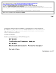
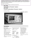
USER’S GUIDE
Installation, Operation, Maintenance Instructions
SC404
Capacitive
Level Sensor
Contents
Introduction . . . . . . . . . . . . . . . . . . . . . . . . . . . . . . . . . . . . . . . . . . . . . . . . . 4
Models & Dimensions . . . . . . . . . . . . . . . . . . . . . . . . . . . . . . . . . . . . . . . . . 5
Wiring Diagram . . . . . . . . . . . . . . . . . . . . . . . . . . . . . . . . . . . . . . . . . . . . . . 6
Mounting Note . . . . . . . . . . . . . . . . . . . . . . . . . . . . . . . . . . . . . . . . . . . . . . 11
Installation . . . . . . . . . . . . . . . . . . . . . . . . . . . . . . . . . . . . . . . . . . . . . . . . . 12
Calibration . . . . . . . . . . . . . . . . . . . . . . . . . . . . . . . . . . . . . . . . . . . . . . . . . 16
Handling . . . . . . . . . . . . . . . . . . . . . . . . . . . . . . . . . . . . . . . . . . . . . . . . . . 18
Technical Specifications . . . . . . . . . . . . . . . . . . . . . . . . . . . . . . . . . . . . . . 19
Trouble Shooting . . . . . . . . . . . . . . . . . . . . . . . . . . . . . . . . . . . . . . . . . . . . 20
Ordering Information . . . . . . . . . . . . . . . . . . . . . . . . . . . . . . . . . . . . . . . . . 21
Terms & Conditions . . . . . . . . . . . . . . . . . . . . . . . . . . . . . . . . . . . . . . . . . 22
Notes . . . . . . . . . . . . . . . . . . . . . . . . . . . . . . . . . . . . . . . . . . . . . . . . . . . . 24
3
Introduction
SC404 - Capacitive
Level Sensor
The SC404 is a capacitance continuous level transmitter with an
integrated electronics module mounted within the housing. This 2 wire
loop powered unit provides a 4-20mA output. Set up and calibration is
achieved with a zero and span adjustment which works best when
starting with an empty tank to set the zero and then filling it to set the
span. This flexible level measurement device works well in many
industrial processes and process media including a variety of liquids,
powders and pastes. The SC404 is made with 316SS rigid rods or
316SS cables (coatings are required for conductive mediums) and
can also be made with a secondary reference rod or reference sheath
built into the process connection.
The wide range of applications for RF analog level measurement
probes (such as liquids, pastes, solids and granules), requires
attention in selecting the correct configuration and installing it in the
proper location. To cater to all applications, Sitron's probes are offered
with different designs and features.
Features
Wide range of applications/industries:
i.e. water, oils, corrosives, solids, powders, grains, etc.
Accurate and reliable measurement
No moving parts - Rugged construction
Can operate at high temperatures and pressure
Functions on conductive as well as non-conductive medias
Sitron-USA - Phone (516) 935-8001 / Fax (800) 516-1656
4
Models and Dimensions
Housing Types
N2
G1
N1
89mm
G2
113mm
122mm
89mm
130mm
118mm
130mm
76mm
126mm
129mm
80mm
50mm
100mm
Mounting Options for SC404
Extended necks for medium temperature (up to 120°C) and high temperature (up to 150°C)
SC404 Standard
SC404 W/
Reference Sheath
SC404 W/
Reference Rod
SC404 w/ Cable
(also w/ reference cable)
25
20
20
66
1”NPT
1”NPT
1 1/2”NPT
½”
1/4”
L
1,6
L
L
½”
½”
Note: Minimal insertion for the SC404 is ½ meter
Process Connections
Tri-Clamp
Threaded
3/4”
1”
NPT
1 ½”
2”
5
BSP
1 ½”
2”
2 ½”
1,75
3”
Flange
TC Connection
Rubber Seal
Process Connection
1”
1 ½”
FF
2”
RF
2 ½”
ANSI 150#
ANSI 300#
Wiring Diagram
SC404 with N1 Housing
A
B
C
A- Adjust Sensibility (Gain)
B- Adjust Sensibility (Sub gain)
C- Adjust Zero (begin scale)
D- Adjust Span (end of scale)
D
SC404
2
2
0
0
Gain
Sub
1
2
3
+ _
1- Power Supply (+)
12...30Vdc / 4...20mA
2- Power Supply ( )
3- Ground
Zero Span
SC404 with G1 Housing
A
A- Adjust Sensibility (Gain)
B- Adjust Sensibility (Sub gain)
C- Adjust Zero (begin scale)
D- Adjust Span (end of scale)
B
C
D
1 2 3
1- Power Supply (+)
12...30Vdc / 4...20mA
2- Power Supply ( )
3- Ground
SC404-G
2
+ _
Sitron-USA - Phone (516) 935-8001 / Fax (800) 516-1656
Gain
On
0
2
Sub
0
Z S
6
Wiring Diagram
Galvanic Isolator - ISO420
111mm
6mm
11 +
IN
_ 12
1 +
4...20 mA
Zone 0
OUT
83.5mm
ISO 420
DIN 35mm
4...20 mA
69.8mm
1- Probe (+)
2- Probe( )
11- Power Supply (+)
12- Power Suppy ( )
_ 2
SC404 with G2 and N2 Housing and internal ISO420
D
C
A- Adjust Sensibility (Gain)
B- Adjust Sensibility (Sub gain)
C- Adjust Zero (begin scale)
D- Adjust Span (end of scale)
B
1 2 3
SC 404
+
-
4...20mA
1- Power Supply (+)
24Vdc / 4...20mA
2- Power Supply ( )
3- Ground
7
24Vdc
A
(+-10%)
Zero
On
2
2
0
0
Gain
Sub
Span
Wiring Diagram
Different wiring scenarios for the N1 electronics
Important:
There are several types of PLC configurations and some of them have the negative terminal
grounded internally. In this case, a galvanic isolator must be used along with the probe to
distinguish both signals (negative and ground).
Connecting directly into the power supply
SC404
2
2
0
0
Gain
Sub
2
1
0 ... 100 %
3
+ _
Zero Span
10...30VDC
4...20mA
12...30Vdc
Ground
4 ... 20 mA
+
-
Power
_Supply
+
Electrical connection using the Galvanic Isolator for a PLC with an active input card.
SC404
2
2
0
0
Gain
Sub
2
1
3
+ _
Zero Span
10...30VDC
4...20mA
24Vdc (+/- 10%)
Galvanic Isolator
IN
4...20 mA
ISO 420
4...20 mA
Zone 0
OUT
_
_ 12
_ 2
+
+
11 +
1 +
Ground
-
PLC
Active PLC input card
Electrical connection using the Galvanic Isolator for a PLC with a passive input card.
SC404
2
2
0
0
Gain
Sub
1
2
3
+ _
24Vdc (+/- 10%)
Zero Span
10...30VDC
4...20mA
Power
Supply
Galvanic Isolator
11 +
IN
4...20 mA
ISO 420
_ 12
_ 2
+
4...20 mA
Zone 0
OUT
-
1 +
Ground
+ _
Sitron-USA - Phone (516) 935-8001 / Fax (800) 516-1656
Passive PLC input card
_
PLC
+
8
Wiring Diagram
Different wiring scenarios for the G1 electronics
Connecting directly into the power supply
1 2 3
0 ... 100 %
SC404-G
On
2
+ _
Gain
0
2
V=10...30VDC
I=4...20mA
Sub
0
Z S
12...30Vdc
4 ... 20 mA
Ground
+
-
Power
Supply
_
+
Electrical connection using the Galvanic Isolator for a PLC with an active input card.
1 2 3
SC404-G
2
+ _
Gain
On
0
2
V=10...30VDC
I=4...20mA
Sub
0
Z S
24Vdc (+/- 10%)
Galvanic Isolator
PLC
IN
4...20 mA
ISO 420
4...20 mA
Zone 0
OUT
_
_ 12
_ 2
+
+
11 +
1 +
Ground
-
Active PLC input card
Electrical connection using the Galvanic Isolator for a PLC with a passive input card.
1 2 3
SC404-G
2
+ _
2
V=10...30VDC
I=4...20mA
0
Gain
On
0
24Vdc (+/- 10%)
Sub
Z S
Power
Supply
Galvanic Isolator
11 +
IN
4...20 mA
ISO 420
_ 12
9
_ 2
+
4...20 mA
Zone 0
OUT
-
1 +
Ground
+ _
_
Passive PLC input card
PLC
+
Wiring Diagram
Different wiring scenarios for the G2 electronics
The G2 offers a built in galvanic isolator. In this case a separate one is not necessary.
Connecting directly into the power supply
1 2 3
SC 404
+
-
0 ... 100 %
4...20mA
24Vdc
(+-10%)
Zero
On
2
Span
2
0
0
Gain
Sub
24Vdc (+/- 10%)
4 ... 20 mA
-
+
+
Ground
Power
Supply
_
Electrical connection for a PLC with an active input card.
1 2 3
SC 404
+
-
4...20mA
24Vdc
(+-10%)
Zero
On
Span
2
2
0
0
Gain
Sub
24Vdc (+/- 10%)
4 ... 20 mA
+
-
+
Ground
PLC
_
Active PLC input card
Electrical connection for a PLC with a passive input card.
1 2 3
SC 404
+
-
4...20mA
24Vdc
24Vdc (+/- 10%)
(+-10%)
Zero
On
2
2
0
0
Gain
Sub
Span
Power
Supply
+ _
4 ... 20 mA
Ground
+
-
Sitron-USA - Phone (516) 935-8001 / Fax (800) 516-1656
Passive PLC input card
_
PLC
+
10
Mounting Note
Materials that are conductive will cause a
short circuit between a bare stainless steel
probe and the tank wall. For that reason we
recommend the use of Teflon or other types
of insulating coatings on the rod's surface
(Fig. 1)
Bare Rod
Coating (PTFE or Halar)
Conductive Medium
Steel Tank
Material build-up also affects the accuracy
of RF capacitive measurements, and
therefore additional adjustment to the
probe's sensitivity is recommended in
applications where build-up is a concern
(Fig. 2)
Fig. 1
Housings must also be compatible with the
requirements for wash-down, wet, and/or
dusty environments. Hazardous
environments may require the housing to be
certified. In addition, the active probe might
need to be intrinsically safe or have an
intrinsic safety barrier (Fig. 3).
The electronic circuitry of the probe
performs several functions such as
rectifying and filtering the incoming power,
generating the radio frequency signal,
measuring the changes in current flow,
analog signal generators and display
meters. The circuitry is provided with
potentiometer adjustments for setting
sensitivity that is located in the housing of
the probe. These adjustments give an
added level of fine-tuning which enable our
customers to control the probe's sensitivity
with greater accuracy (Fig. 3).
Fig. 2
Adjust Sensitivity
1 2 3
SC 404
Variation in current input (power supply) to
the probe will affect the output. Therefore, a
stable power supply should be available
(Fig. 4).
Fig. 4
Wire Shield
Conduit
+
-
4...20mA
24Vdc
(+-10%)
Zero
On
2
Span
2
0
0
Gain
Sub
Cable
Wires
Fig. 3
Build up
Power Supply
11
Conduit
Installation
Fig. 1
500mm
When installing the probe either directly to the
tank, or utilizing a connection, the capacitance
probe should be mounted on the top of the tank,
never on the side or angle, so that the rod stays
parallel to the tank wall (Fig. 1 correct Fig. 2
Incorrect).
The mounting location of the probe should stay
clear away from the point where the medium
enters, this will avoid false reading from the sensor
while being filled (Fig. 1 correct Fig. 2 Incorrect).
The recommended distance of installation of the
probe from the internal wall is a minimum of
500mm, and from the tip of the rod to the bottom of
the tank is 100mm, this will prevent a false signal
and possible build up between the wall and probe
(Fig. 1 correct Fig. 2 Incorrect).
100mm
Fig. 2
Sitron - Equip. Eletrônicos Ltda. - Fone/Fax (5511) 3825-2111 / 3825-2171
12
Installation
Sheath
Rod
Fig. 1
Level
The tank must be free from turbulence or
vortices throughout use. If this is not
possible we highly recommend a stilling
well or sheath (Fig. 1 correct, Fig. 2
incorrect).
Ensure that mounting position does not
interfere with any obstructions wthin the
vessel or tank (Fig. 1 correct, Fig. 2
incorrect).
Fig. 2
13
Installation
Fig. 1
500mm
When installing the SC404 with cable and
reference be sure that they are well connected
to the bottom of the tank and that it has no slack.
(Fig. 1 correct Fig. 2 Incorrect).
The mounting location of the probe should stay
clear away from the point where the medium
enters, this will avoid false reading from the
sensor while being filled (Fig. 1 correct Fig. 2
Incorrect).
Isolator
The recommended distance of installation of
the probe from the internal wall is a minimum of
500mm, and from the tip of the pendulum to the
bottom of the tank is 100mm, this will prevent a
false signal and possible build up between the
wall and probe (Fig. 1 correct Fig. 2 Incorrect).
If the cable is secure to the bottom of the vessel
it must be isolated and the vessel is steel it must
be isolated so that it does not create a short
circuit.
100mm
Fig. 2
Sitron-USA - Phone (516) 935-8001 / Fax (800) 516-1656
14
Installation
Rod
Reference Rod
Level
Fig. 1
In order to achieve a linear output
signal, the main rod of the probe
must have a parallel reference
either to the tank or to a
secondary reference rod or
sheath. If the probe is mounted
without this parallel reference
within a cylindrical tank that is
mounted on its side, the output
signal will not be linear. Please
consult one of our applications
engineers if you have further
questions (Fig.1 correct Fig. 2
incorrect).
Single Rod
Fig. 2
Level
L=y
L=z
L=x
15
Calibration
Adjustment (4-20mA):
It is recommended that an multimeter be connected
according to the figure below (fig.5) to monitor the
current value during the calibration. Prior to
calibration it is recommended that both
potentiometers are reset. Turn both potentiometers
counter-clockwise until they stop (or approximately
20 turns) (Fig. 1).
1) Drain the tank to minimum level (Zero% or 4mA).
Fig.1
2
0
Sub
Zero
2
Span
2
0
0
Gain
Sub
Fig.3
Zero
On
2
Span
2
0
0
Gain
Sub
Fig.4
6) Use the Span potentiometer to set the current
value for the actual level to 20mA. Turn the
potentiometer clockwise to increase current. Turn
the potentiometer counter-clockwise to decrease
current (Fig.4).
7) If the current is lower than 20mA after fully turning
the Span Potentiometer clockwise, it is necessary to
increase the sensitivity by selecting the next level of
the switch (Sub and Gain). If the current still remains
lower than 20mA, continue on to the next level until
you achieve 20mA.
0
Gain
On
4) After calibrating the minimum value (4mA), fill up
the tank to maximum level (100% - level).
5) The Sub and Gain switches should be in the same
position as adjusted to 4mA.
Span
2
Fig.2
2) Select the Gain switch 1,2,3 and Sub positions
1,2 or 3. It is recommended to begin with Gain switch
1 and Sub position 1 (Fig. 2).
3) Use the Zero potentiometer to set the current
value for the actual level to 4mA. Turn the
potentiometer clockwise to increase current. Turn
the potentiometer counter-clockwise to decrease
current (If the adjustment wasn't possible, alter the
Sub and Gain position and try in adjust the minimum
value (4mA) through the Zero Potentiometer)(Fig.3)
Zero
On
Zero
On
2
Span
2
0
0
Gain
Sub
Fig.5
8) With the 20mA signal adjusted it is best to readjust the Zero. Drain the tank back down to the
starting level and re-adjust (if necessary) the
minimum level to 4mA one more time. After this
stage, set-up is complete.
Sitron-USA - Phone (516) 935-8001 / Fax (800) 516-1656
16
Calibration
The dielectric value varies according to
the product, temperature, pressure,
rod's length and shape of the tank.
Because of these variations, the
parameters of the capacitive probe need
to be adjusted according to each
application as well as each tank. While
the SC404 can be tested on a bench, the
results of calibrating it will not be the
same as calibrating the unit within the
actual tank that you plan on installing it in.
Nylon-N1
SC404
2
2
0
0
Gain
Sub
1
3
2
+ _
SC404
2
Zero
2
0
0
Sub
Gain
1
3
2
+ _
Zero Span
10...30VDC
4...20mA
Aluminum-G1
The SC 404 has 3 stages of sensitivity
and that can be adjusted by a selective
switch. Each stage has 3 subdivisions
(1, 2, 3) for the SC404 and 4 subdivisions
(1, 2, 3, 4) for the SC404-G to be
combined with the selective switch.
Check the values on the chart below
according to your application.
2
Gain
0
2
Sub
0
1 2 3
Capacitive Range for the SC404-G:
SC404-G
2
+ _
Gain
1) 1600pF to 5500pF
Sub
1 - 3750 to 5500pF
2 - 2500 to 3750pF
3 - 1600 to 2500pF
2) 400pF to 1500pF
1 - 900 to 1500pF
2 - 600 to 900pF
3 - 400 to 600pF
3) 100pF to 330pF
4) 25pF to 150pF
17
1 - 225 to 330pF
2 -150 to 225pF
3 -100 to 150pF
1 - 150 to 100pF
2 -100 to 70pF
3 - 70 to 25pF
On
Gain
0
2
V=10...30VDC
I=4...20mA
Sub
0
Z
Aluminum-G2
On
Zero
2
2
0
0
Gain
Sub
1 2 3
SC 404
+
-
4...20mA
24Vdc
(+-10%)
Zero
On
2
2
0
0
Gain
Sub
Span
S
Handling
Probes:
Fig. 1
Seal the thread with Teflon tape before
installation (Fig. 1).
Do not turn or handle by the housing (Fig. 2).
Fig. 2
When tightening the sensor, use only use the
316S.S. hexagon fitting to achieve a seal, do not
twist with the body of the sensor. (Fig. 3)
The probe should not be dropped or suffer any
impact or fall that could damage the electronics or
the coating of the probe (Fig. 4 and 5).
Periodic visual inspection of the probe is required
to check for corrosion or deposit build-up. If
deposits are found, clean the sensor to ensure
optimum performance.
Fig. 3
Fig. 4
Care should be taken when handling and installing
probes with coated rods to avoid scratching them.
Scratching the coating could interfere with the
probe performance.
Fig. 5
When cleaning the rod use a soft brush or any
other similar object.
Sitron-USA - Phone (516) 935-8001 / Fax (800) 516-1656
18
Technical Specifications
SC404
1 2 3
SC404
2
SC 404
1 2 3
2
SC 404
+
-
4...20mA
0
0
+
-
1 2 3
4...20mA
Sub
Gain
24Vdc
1
2
3
Zero Span
Zero
Housing N1
2
2
0
0
Gain
Sub
Span
Housing N2
Application
Operating Voltage
Current Consumption
Adjustment
+ _
V=10...30VDC
I=4...20mA
24Vdc
SC404-G
2
(+-10%)
On
+ _
(+-10%)
Gain
2
0
2
Sub
Z
0
Sub
Housing G2
Housing G1
Continuous Level Measurement for Liquids and Solids
12..30Vdc Housing (N1/G1)
24Vdc (+/- 10%) / Housing G2/N2 & (N1/G1 w/ ISO420)
22mA max
Zero & Span Potentiometer
100 to 5500pF
Frequency Oscillation
400 kHz
Output
4...20mA
Accuracy
0.5%
Repeatability
+/- 1mm
--
Electrical Connection
Cable gland - 1/2” NPT conduit entry or M12 connector
Process Connection
3/4” to 1 1/2” BSP or NPT Flange or Sanitary Connections
Wetted Parts
316 Stainless Steel, PTFE
Enclosure Material
Glass filled nylon, Aluminum
Max Pressure
290 PSI (20 Bar)
Operating Temperature
Class Protection
19
Span
2
0
Gain
S
Sensitivity Range
Level Indication
Zero
On
On
0
14 to 248º F (-10 to 120ºC)
(IP 65)
Trouble Shooting
Fault
Cause
Solution
No power supply
Verify power supply
Inadaquate connection
Verify the polarity of the power supply
Probable short circuit
Verify that the rod is coated for
conductive mediums
Signal over
22mA
Sensitivity to high
Adjust sensibility again
Signal Fluctuating
Lack of signal from
referance rod
Verify the grounding
Signal under
20mA
Sensitivity to low
Adjust sensibility again
No signal
Add a Reference
Reference is incorrect
Sheath the rod
Lack of linearity
Coating on the rod
is damaged
Send back for repair
Sitron-USA - Phone (516) 935-8001 / Fax (800) 516-1656
20
Order Information
MODEL
SC404
SIZE
4
5
6
7
9
Q
X
3/4”
1”
1 1/2”
2”
3”
4”
OTHER
PROCESS CONNECTION TYPE
B
D
E
F
K
N
T
X
BSP
FLANGE ANSI 150#
FLANGE ANSI 150#
FLANGE ANSI 150#
FLANGE ANSI 150#
NPT
TRI-CLAMP
OTHER-SPECIFY
CARBON STEEL PAINTED
316 SS
PVC
304 SS
COATING
S
H
N
T
T
X
M
NONE
HALLAR COATED
NYLON 11 COATED
PTFE TUBED (UP TO 120C)
PTFE TUBED (CABLE)
OTHER-SPECIFY
PTFE TUBED FOR HIGH TEMP. (UP TO 200C)
TYPE OF ROD OR CABLE
R RIGID ROD-1/2”(12.7mm) or 5/8”(16mm)-316SS
RR RIGID ROD+REFERENCE ROD-1/2”(12.7mm) or 1/4”(6.3mm)-316SS
M
C
STEEL CABLE-6.0mm
ROD (½") and SHEATH 316SS
INSERTION LENGTH
L
SPECIFY
HOUSING
N1
G1
N2
G2
SMALL NYLON
SMALL ALUMINIUM
LARGE NYLON
LARGE ALUMINIUM
ELECTRICAL CONNECTION
1
2
4
5
6
7
9
C
1/2" BSP
CABLE GLAND W/ 1/2" BSP
3/4" BSP
CABLE GLAND W/ 3/4" BSP
1/2" NPT
CABLE GLAND W/ 1/2" NPT
3/4" NPT
CABLE GLAND W/ 3/4" NPT
OPTIONS
SC404
21
MT
Medium Temp - 50mm
316SS Neck (80-120C)
AT
High Temp - 100mm
316SS Neck (80-150C)
Terms & Conditions
Sitron's TERMS & CONDITIONS
Design: Sitron reserves the right to make any alterations or changes necessary to improve
the Products, correct defects or to make the Products safer, without prior notice or consent by
Buyer.
Pricing: All stipulated amounts shall be in US dollars and all prices quoted are valid for thirty
(30) days from date of offer, unless otherwise stated.
Safety and Instructions: The Buyer ensures that it and all its representatives and agents will
observe all safety and technical instructions in Sitron's operating manuals, catalogs or other
directions or instructions (either written or verbal).
Delivery and Freight: All goods are sold FOB point of shipment, Brasil. Transportation to the
destination is the Buyer's responsibility and Buyer alone shall bear the cost of freight, optional
or other shipping requirements, and or insurance. Sitron shall not be liable for loss or damage
to the Products after said Products are delivered to or received by the shipper/carrier, and all
risk of damage or loss shall immediately pass to Buyer.
Receiving, unloading and storing of Products will be the responsibility of the Buyer.
Buyer also accepts that courier may choose to return Products to Sitron if any local taxes or
duties are not paid by Buyer at point of delivery. Buyer must make any and all claims for
corrections or deductions within ten days of the delivery of the Products.
Shipment Delays: Sitron has no control over the length of time shipments may be held at
customs, etc. For this reason, Sitron commits only to a "shipment date", not a "delivery date".
Buyer shall not hold Sitron liable for claims resulting from delay in shipment except in cases
where these terms are accepted in writing by Sitron. Acceptance of delivery of Products by
Buyer shall constitute a waiver of all claims for delay.
Partial Deliveries: While Sitron strives to deliver all orders on time and complete, Sitron
reserves the right to make partial deliveries when necessary.
Changes: Any changes initiated by the Buyer which affects the products specifications;
quantities ordered; delivery schedule; method of shipment or packing; or delivery location,
must be made in writing and signed by both parties.
In this case, Sitron reserves the right to adjust the pricing and or delivery of the order, which
will be agreed to by both parties before further work is performed on the order. Any such
requests will be priced according to the scope of changes and the status of the current order.
Customer must sign and return or acknowledge approval of drawings along with any
Purchase Order. If approval drawings are not returned with order, the delivery date may be
held or pushed back until Customer has acknowledged approval.
Cancellation: Any cancellation of the Contract by the Buyer shall be effective only if made in
writing and accepted, in writing by the Sitron. In such a case, Sitron is entitled to reasonable
cancellation charges including but not limited to labor, material and other related expenses.
Sitron-USA - Phone (516) 935-8001 / Fax (800) 516-1656
22
Terms & Conditions
Termination Fee Schedule:
Order entered but not released for manufacturing
Order in any stage of production
Order complete and ready for shipment
10%
75%
100%
Warranty: Sitron warrants its product against manufacturing defects in material and
workmanship, when installed in applications approved by Sitron, for a period of one year from
the date of original shipment, unless otherwise stated in writing by Sitron.
Sitron is not responsible for damage to Sitron's Products or other equipment or products
because of improper installation or misapplication of the Products by Buyer. Installation or
startup of Sitron's equipment must be performed under the guidelines set forth in Sitron's
instruction manuals, wiring diagrams, etc., or performed under the direct supervision of
Sitron's field technicians or Sitron's authorized Sales Representatives, in order to be covered
by Sitron's warranty.
Sitron shall be under no liability in respect to any defect from fair wear and tear, willful damage,
negligence, abnormal working conditions, failure to follow Sitron's instructions (whether
written or verbal), misuse, modification or alteration or attempted repair of the Goods without
Sitron's approval.
Sitron shall not be liable under the above warranty (or any other warranty, condition or
guarantee) if the total price for the Products or the payment of Services rendered has not been
paid by the due date for payment.
The Buyer must make all tools, resources or personnel available to help Sitron to diagnose the
defect without any back charge. In absence of Buyer's cooperation in this regard, there shall
be no liability under the above Warranty.
Sitron's liability under this warranty shall be limited to repair or replacement at Sitron's option
of such defective Products, FOB factory, upon proof of defect satisfactory to Sitron. Warranty
does not include transport.
Return Goods: No goods may be returned without Sitron's permission and an RMA number.
Sitron assumes no responsibility for return shipments made without permission. In issuing
credit for such shipments, Sitron reserves the right to charge a restocking fee dependent on
Sitron's ability to recondition and resell the returned equipment.
Insurance: The responsibility for insuring the Goods after the risk in them has passed to the
Buyer shall be that of the Buyer.
Confidential Information: All drawings, specifications, and technical information provided
by either Buyer or Sitron shall be treated as confidential and shall not be disclosed to anyone
other than those who require it as part of the fulfillment of the order. Buyer agrees that the
designs and/or any other related material provided are and remain Sitron's exclusive property
and that the Buyer acquires no right, title or interest to this intellectual property, whether in
whole or in part.
Errors: Sitron reserves the right to correct all typographical or clerical errors or omissions, in
its prices or specifications.
23
Sitron - Brasil
R. Baronesa de Itu, 83
São Paulo - SP - 01231-001
T.: (5511) 3825-2111
F.: (5511) 3825-2171
Sitron - USA
1800 Prime Place
Hauppauge, NY 11788
PH: 516-935-8001
FX: 800-516-1656
www.sitron.com
BRASIL: [email protected]
USA / Other Countries: [email protected]