1
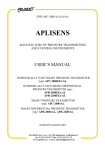
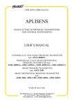
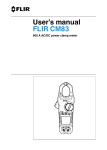
the smart Water Saver RainSmart Installation & User Guide TABLE OF CONTENTS PAGE 2 TOPIC 3 PLEASE READ THIS FIRST 4 GENERAL INFORMATION 4 MOUNTING CONTROLLER 4 WIRING LEVEL SWITCH AND MAINS VALVE 5 RAINSMART QUICKSETUP 6 INSTALLING DUAL NON RETURN VALVES 6 FITTING THE LEVEL 8 AUTO MAINS VALVE 9 USING RAINSMART 10 BOX CONTENTS 10 TECHNICAL SPECIFICATIONS 13 TROUBLE SHOOTING PLEASE READ THIS FIRST WARNINGS • • • • • • • • • • • • • • • • Before installing the controller please read all instructions carefully. Failures caused by incorrect installation are not covered by the warranty. The rainsmartTM unit involves connection to the mains water supply. It must therefore be installed by a licensed plumber. AS/NZ 3500.1.2.1998 requires that dual non-return valves be used to protect against cross connection between mains water and tank water. Your local supply authority may have additional requirements. Seek advice from your licensed plumber or local council. Installation of the rainsmartTM controller should be in accordance with AS/NZ 3500.1 – Plumbing and drainage water services. This equipment is not suitable for use with flammable, corrosive and other materials of hazardous nature. Insects and vermin are attracted to electrical equipment. Ensure if the controller is susceptible to vermin infestation you implement a suitable pest control plan. The mains electrical connections and checks must be made by a qualified electrician and comply with applicable local standards. The low voltage connections need not be carried out by a qualified electrician, but should be done in compliance with applicable standards. Do not use long extension leads as they may damage the equipment. Ensure rainsmartTM is isolated from electrical supply during installation. Ensure rainsmartTM is isolated from electrical supply during and subsequent maintenance. The mains valve can cause injury. Do not operate while not plumbed in. The pump must connect directly to the rainsmartTM controller not the power point. If the pump is connected to the power point the pump will run constantly, shortening the life of the pump and potentially running the pump dry. The rainsmartTM is not a toy. Keep away from children. Pipes and outlets connected to the rainsmartTM must be clearly marked at 1m spacings with the wording “RAINWATER”. If the power supply cord or pump interconnection is damaged, it must be replaced by an authorized RAINSMART AUSTRALIA Service Agent, or suitably qualified person. We recommend using a residual current device RCD (also known as earth leakage breaker). Contact a qualified electrician for more information. 3 RAINSMARTTM INSTALLATION AND USER GUIDE Thank you for choosing the Australian owned, designed and manufactured RainSmartTM. We trust that you will enjoy the quality and freedom the RainSmartTM has been designed to provide. Please read this instruction guide carefully to make sure the RainSmartTM is installed correctly to ensure its many design features are used to your full advantage. The micro-processor controlled RainSmart can be installed with many different brands and models of pressure switched pumps in such a way that you don’t need to sacrifice choice. An optional reserve level height combined with Auto and Manual overrides ensure flexibility for optimum use. The product has been designed and complies with relevant electrical standards and has Watermark approval number 23029. 1. GENERAL INFORMATION The RainSmartTM controller can be used in either above ground or below ground tank installations. A pressure pump is required. 2. MOUNTING CONTROLLER The controller must be installed on a vertical surface using the supplied mounting brackets. Install the controller within 2 meters of a protected power supply and no more than 10 meters from the tank level switch location or the Auto mains valve supplied unless extension cables are used. SEE FIG. 2 FIG. 2 3. WIRING LEVEL SWITCH AND MAINS VALVE The low level switch and Auto Mains Valve are low voltage for your safety so the extra lead lengths may be shortened to suit. Be careful to return the correct wires to each of the termination points as supplied if shortening is undertaken. See RainsmartTM QUICK SETUP 4 RainsmartTMQUICKSETUP D C A B PhotoofFloatandLead – rainsmartmainspowerplug B – Powersocketforpumppowerplug C – SocketforMainsAutoValve D – SocketforFloatlead A INSTRUCTIONS Aintoamainspoweroutlet ConnectpumpintoB ConnectMainsAutoValvetoC ConnectFloattoD 1. Connect 2. 3. 4. NOTE: CandDcannotbeinterchanged. PhotoofMainsAutoValveandLead 55 4. INSTALLING DUAL NON RETURN VALVES (SEE FIG. 1) The RainSmartTM comes with two 20mm dual non return valves, one for the mains water pipe and one for the pump supply pipe. It is necessary to install a dual non return valve on an upstream position from the RainSmartTM auto mains water valve to adhere to government requirements. Ensure the dual valve included is positioned in the correct direction. The other 20mm dual non-return valve also included, should be installed as shown in the diagram down stream of the external tap tee section. This will ensure you can take advantage of your tank water regardless of the level operation used to control in house (Laundry & Toilet) supply. This tap will only use tank water from the pump if installed correctly, this means that when restrictions are applied you can keep using your tank water when others cannot. 5. FITTING THE LEVEL (FLOAT SENSOR) a) Counterweight Installation: Assemble the level switch components. Peel the plastic clip from the counter weight, fit this clip to the lead at approximately 200mm from the float head. Feed the lead through the weight from the cone end until the cone rests on the plastic clip. FIG. 3 6 b) Float installation: See Steps 1 to 4. STEP 1 STEP 3 STEP 2 STEP 4 7 7 Using the cable gland provided drill a 19 mm hole near the hatch door or down pipe water strainer at the top of the tank in a position of easy access. Fit the Gland and feed the cable through the gland hole from inside the tank. Tighten the gland, it will support the weight of the level switch. Tie float and mains valve cables to the mains power cable using the cable ties supplied, to provide strain relief on the connectors. To ensure you always have the water you need outside, fit the level according to your desired reserve level. You can do this by extending the level outside the tank and checking the low level position against the pump suction pipe at the bottom (make sure the switch is at least 100mm above the pump feed pipe). Mark the level switch lead at the desired depth. Note: You may wish to use halfway as your required level position thus keeping one half for outside use when times are dry. It is your choice. Use your water your way. You can adjust this level to suit your requirements by releasing the gland and feeding the lead either way to lengthen or shorten inside the tank. Feed the lead of the level switch through a hole 19 mm in size from the top of the water tank. Once the lead has been fed from inside the tank feed the lead through the retention gland and tighten at your required level by using the tank depth as a guide. Cap the hole in the tank using the gland. Note: Ensure you consider what reserve you would like in the tank and that the length of cable inside the tank allows the level room to fully extend. Wire the level switch as shown into the plug socket fitting supplied and marked on the bottom of the RainSmartTM controller. To test the level before installation, switch power onto the RainSmartTM controller and move the level switch from a low to a high position. When the switch is held in the low position the mains light will illuminate and if the Auto Mains Valve is also plugged in, this will open. When the level is held up the Auto Mains Valve will close. 6. AUTO MAINS VALVE (SEE FIG. 1) Warning: Do not place your fingers or any other part of your body inside the valve body at any time as the valve has an operating pressure of 1600kPa which could cause major injury. This valve is low voltage so that it can be installed safely without the need for an electrician. The valve is designed and supplied in a normally open position and offers full flow through the orifice. The blue valve controller should be installed in an upright position to ensure long life is achieved. The valve is light weight and can be supported by normal pipe work. Place the supplied cover over the valve for extra protection. Before installing check that the valve operates normally by plugging the device into the connection marked on the bottom of the RainSmartTM controller. When the level switch is connected and in the low position the valve should be open. If power is switched off to the RainSmartTM controller, the Auto Valve should be open. You may use the test button to check the operation. Fit the Auto Mains Valve to the Mains water pipe down- stream from the dual non-return valve (this should be carried out by a licensed plumber) and plug the low voltage cable into the socket fitting supplied and marked on the bottom of the RainSmartTM . Refer Fig. 1. Note : A dual non-return valve needs to be fitted on the upstream side of the Auto Valve. This is a government requirement to ensure Rain tank water does not mix with municipal mains drinking water. 8 7. USING RainSmartTM There are two buttons located on the RainSmartTM controller to provide you with greater freedom to use your tank water the way you want: 1. Test button: forces mains valve to change position for 15 secconds. So, if on tank water it will change to mains water and if on mains water, it will change to tank water. 2. Auto or Manual selection for operation of the pump being used to supply water from the tank. Auto, if selected power will be cut to the pump when the level switch senses a low level condition in the tank. Manual if selected, power will remain supplied to the pump regardless of a low level condition. NOTE: the selected operation is displayed by the LED display. NOTE: See the Level setting information to ensure you get the most from your RainSmartTM installation. The LED lights are provided so that you know what the status of your water usage is and include: Power, when the light is illuminated there is power to the RainSmartTM controller, in case power is lost the Auto Mains valve will open to ensure you have water available to flush Toilets and for laundry regardless. Mains, when mains water is being used to supply the toilets or laundry because a low level is being sensed. Tank, when the rain water is being used to provide water to toilets and laundry because an acceptable water level is being sensed. Auto, when the pump is controlled by the low level switch. The pumps power supply will be cut in low level condition. Manual, when the pump is not controlled by the low level switch. The pump always has power regardless of a low level condition. Note: The mains valve will behave normally regardless of the Auto Manual selection. If lights are flashing, check the level switch is connected and or check operation. Note: Most pumps have loss of prime switches fitted which turn the pump off when the water gets to low. If the pump loses prime, refer to the pump manufacturer’s manual to reset it. Selecting manual on the RainSmartTM allows you to use all of the tank water if you wish giving you choice. 9 8. BOX CONTENTS AND TECHNICAL SPECIFICATIONS a. CONTENTS OF BOX The following parts have been supplied in the box: • • • • • • 1 x Rainsmart controller 1 x mains valve 2 x non-return valves 1 x float sensor 2 x cable ties (used for strain relief) 1 x cable gland (to tie float valve to top of tank) b. TECHNICAL SPECIFICATIONS Operating current 240V ac, 50 Hz Maximum pump current 10 Amps Operating Ambient Temperature 0 degrees min – 50 degrees max IP Rating 43 10 11 FIG. 1 Legend: 1,3 - Dual Non-return Valves 2 - Mains Auto Valve 12 9. TROUBLE SHOOTING NOTE: A pump failure will result in loss of water supply to the connected points. It is possible to manually switch to mains supply. This is a feature of RainSmart. If a pump failure resulted in an automatic “Change Over” to Mains Supply, as occurs with some other systems, you would be unaware that mains water was being used when instead you wished to use rain water from the rain water tanks. This would be defeating the purpose of the purchase of the RainSmart. In the unlikely event of a “Pump Failure”, remove power from the RainSmart unit. This will result in automatic “Change Over” to the “Mains Supply”. The pump can now be disconnected and repaired. TABLE 1 - FAULT CONDITIONS - The fault conditions table refers to tests outlined TABLE 2 – GENERAL TESTS. 1 Symptom Conditions - Suggested Resolutions No water Supply at all Tank has ample rainwater and indicator shows “Rain Water” ¾ Perform General Test E (Verify pump outlet) ¾ Check pump for loss of prime ¾ Pump May be faulty Rainwater tank is empty and the indicator light shows “Rain Water” ¾ Perform General Test B (verify rain water level) ¾ Perform General Test B2 (Verify float sensor) 2 No water being delivered by pump ¾ Perform General Test A (verify RainSmart power supply) ¾ Perform General Test E (verify pump outlet). If RainSmart pump supply ok, pump may have loss of prime or may be faulty 3 Poor Water Pressure ¾ If there is a filter “In Line” this may require replacement or cleaning ¾ If the pump has to lift water (especially if the rainwater tank is getting lower) , it is possible that “cavitation” has occurred and pump has lost prime ¾ Is the pump suitable for the operating condition? ¾ Pump Capacity may be not adequate for the application 4 Pump will not switch off 5 Pump will not switch on ¾ Perform General Test E (verify pump outlet) ¾ If this all works OK, Plug the pump into a normal power outlet and test. Turn rainwater tap on: if the pump does turn on it is faulty 6 Pump still running when mains water in use ¾ Pump may be in manual mode and an external rainwater tap left on. ¾ If RainSmart has “Pump Auto” & “Mains Water” indicators ON, the Control unit has failed Ensure that all supply points connected to RainSmart are OFF including toilet not running ¾ There could be a leak in water line or washing machine/Toilet ¾ Pump pressure sensing mechanism has failed 13 7 Tank empty and no mains water supply ¾ Perform General Test B2 (Verify float sensor) ¾ Perform General Test D (Verify Mains Valve operation) 8 Mains water/Tank water indicator incorrect ¾ Verify rain water level in tank ¾ Perform General Test B2 (Verify float sensor) 9 No water on dedicated rain water tap Check the rain water level in tank. May be too low Check RainSmart: if it indicates mains water and there is still a reserve level, change RainSmart Pump mode to Manual. ¾ Perform General Test A ¾ Perform General Test B (Verify Rain water level) ¾ Perform General Test B2 (Verify float sensor) ¾ Perform General Test E (verify pump outlet) 10 No water to Laundry & Toilets Check Rain Water level & Float operation ¾ Perform General Test B (Verify Rain water level) ¾ Perform General Test B2 (Verify float sensor) Tank empty & “Mains Water” indicator ON ¾ Perform General Test D (Verify Mains Valve operation TABLE 2 - GENERAL TESTS The following general tests must be used in conjunction with TABLE 1 – FAULT CONDITIONS. Please refer to TABLE 1for trouble shooting tips. A Test Conditions - Suggested Resolutions Verifying RainSmart Power Is the RainSmart Plugged in and switched on Are any RainSmart indicator lights General Tests ¾ Power Ok Verify using another appliance (i.e. hairdryer) that the power outlet is operating. 14 B Verifying Rainwater level ¾ If power at outlet and no power on RainSmart, RainSmart may need repairs ¾ If NO power at outlet seek advice from a qualified electrician Rainwater level in tank Ok ¾ RainSmart ”Rain Water” indicator ON? Check Float sensor is correctly installed? Possible Float sensor Failure? Rain water tank low ¾ RainSmart ”Mains Water” indicator should be ON! And RainSmart operating on mains water. B2 Verifying Float Sensor ¾ If possible, retrieve the float sensor from the tank. Both of the conditions should work otherwise there is a failure o Let the float sensor dangle (float is pointing down with lead coming out of the top. The RainSmart should indicate “Mains Water”. o Raise the float level so the float is pointing up with the lead hanging out of the bottom. The RainSmart should indicate “Rain Water” If either of the above tests fail, there is a problem with the float sensor. C Verify Pump manual/auto mode Ensure that the indicator on the RainSmart unit changes from “Pump Auto” to “Pump Manual”. General Tests ¾ If not, return the RainSmart unit for service as a failure has occurred D E Verify Mains Valve operation Press the test button Verify Pump Outlet Unplug the Pressure Pump from RainSmart and plug-in a portable appliance instead ¾ Set the mode to pump manual mode o The appliance should turn on ¾ Mains valve operates. There is a visual indicator on top of the mains valve that indicates the direction of the ball valve. When pressing the test button this should rotate and then 15 seconds later rotate again. If mains valve does not operate, check the connection of the mains valve to the RainSmart. If this is ok, then either the mains valve or RainSmart may be faulty. If the appliance does not operate, there is a problem with the RainSmart control unit If the appliance turns on, the pressure Pump has failed! 15 ns provided. inside. instructions provided. ons inside. the smart Water Saver RAINSMART AUSTRALIA PTY LTD ACN 136 188 586 PO BOX 835 LUTWYCHE Q 4030 P: 1300 545 857 F: 07 3863 0149 www.rainsmartaustralia.com.au DESIGNED thePROUDLY smart Water Saver AND MANUFACTURED INAUSTRALIA AUSTRALIA, RAINSMART PTYFOR LTD ACN 136 188 586 AUSTRALIAN CONDITIONS PO BOX 835 LUTWYCHE Q 4030 P: 1300 545 857 F: 07 3863 0149 www.rainsmartaustralia.com.au PROUDLY DESIGNED AND MANUFACTURED IN AUSTRALIA, FOR AUSTRALIAN CONDITIONS during power failures, pply during power failures, ails. mp fails. Fully automatic operation with no loss of water supply during automatic operation with no level loss ofiswater during fails. power Fully failures, when tank water lowsupply or if pump power failures, when tank water level is low or if pump fails. PATENT PATENT PENDING PENDING AU Pat App. AU Pat App.No.2009902533 No.2009902533