1
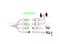
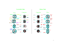
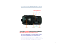
Joystick Controller (IM-50A) Brief User Guide Speed Levels/Error Codes* Slow Speed Fast Speed Horn Battery Levels Joystick Power Off Power On *Error Codes (5 red LED’s from left to right ) and Meanings: (The controller will not start motor if it detects any error) The The The The The first LED flashing -- Low voltage (below 19.5Vdc) second LED flashing – No joystick detected third LED flashing – Battery charging prohibition forth LED flashing – Motors not connected properly fifth LED flshing – Parking brakes dis-engaged 3-1 Wheelchair Joystick Controller Wiring Diagram to motors connect to to joystick controller connect to Battery Box connect to Battery Charger 3-2 Controller Side Motor Side Connectors Connectors Wires green yellow orange white yellow orange brown pink Wires black red red red black red red red red red black black blue red black black pin to pin red 3-3