1
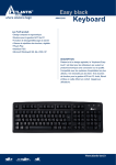
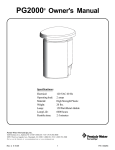
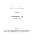
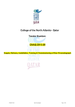
SPACOMMAND® SPA-SIDE REMOTE FOR EASYTOUCH®, INTELLITOUCH® and COMPOOL® CP3800 SERIES CONTROL SYSTEMS INSTALLATION AND USER’S GUIDE IMPORTANT SAFETY INSTRUCTIONS READ AND FOLLOW ALL INSTRUCTIONS SAVE THESE INSTRUCTIONS SPACOMMAND® Spa-Side Remote Installation and User’s Guide Technical Support Phone: (800) 831-7133 - Fax: (800) 284-4151 visit www.pentairpool.com and www.staritepool.com: CONTENTS IMPORTANT SAFETY INSTRUCTIONS ............................................................... i SpaCommand Spa-Side Remote Overview ............................................... 1 Upgrading iS10 Remote .................................................................... 1 Operating the SpaCommand Spa-Side Remote ......................................... 1 SpaCommand Spa-Side Remote Buttons .................................................. 2 EasyTouch and IntelliTouch button assignments ............................... 3 Compool button assignments ........................................................... 3 SpaCommand Spa-Side Remote Kit Contents .......................................... 4 SPACOMMAND SPA-SIDE REMOTE INSTALLATION .............................. 5 Recess Mount Installation (with Mud-Box) ........................................ 5 Spa-Side Remote Mounting Space Dimensions ............................... 5 RECESS MOUNT INSTALLATION (without MUD-BOX) ............................. 6 SURFACE MOUNT INSTALLATION (without MUD-BOX) ........................... 8 REPLACING EXISTING SPACOMMAND REMOTE .................................. 10 UPGRADE EXISTING iS10 REMOTE ...................................................... 11 WIRING THE SPACOMMAND REMOTE TO THE LOAD CENTER ............ 15 Adding Multiple SpaCommand Spa-Side Remotes (IntelliTouch) ............... 17 Setting up SpaCommand Spa-Side Remote (IntelliTouch) ......................... 18 Setting up SpaCommand Spa-Side Remote (EasyTouch) .......................... 19 Compool SS8 Remote Upgrade Installation ............................................... 20 P/N 521198 Rev. B 11/12 SPACOMMAND® Spa-Side Remote Installation and User’s Guide i IMPORTANT WARNING AND SAFETY INSTRUCTIONS INSTALLERS, POOL OPERATORS AND POOL OWNERS MUST READ THESE WARNINGS AND ALL INSTRUCTIONS BEFORE USING THE SPA-SIDE REMOTE. Most states and local codes regulate the construction, installation, and operation of public pools and spas, and the construction of residential pools and spas. It is important to comply with these codes, many of which directly regulate the installation and use of this product. Consult your current local building and health codes for more information. IMPORTANT NOTICE - Attention Installer: This Installation and User’s Guide (“Guide”) contains important information about the installation, operation and safe use of this spa-side remote. This Guide should be given to the owner and/or operator of this product. Before installing this product, read and follow all warning notices and instructions in this Guide. Failure to follow warnings and instructions can result in severe injury, death, or property damage. Call (800) 831-7133 for additional free copies of these instructions. Please refer to www.pentairpool.com for more information related to this products. Control System is intended to control heaters with built-in high limit circuits ONLY. Failure to do so may cause property damage or personal injury. Do not use this product to control an automatic pool cover. Swimmers may become entrapped underneath the cover. The SpaCommand® Spa-Side Remote must be installed by a qualified pool professional in accordance with the current National Electrical Code (NEC), NFPA 70 or the Canadian Electrical Code (CEC), CSA C22.1. All applicable local installation codes and ordinances must also be adhered to. Improper installation will create an electrical hazard which could result in death or serious injury to pool users, installers or others due to electrical shock, and may also cause damage to property. Always disconnect the power to the pool light at the circuit breaker before servicing the light. Failure to do so could result in death or serious injury to serviceman, pool users or others due to electrical shock. READ AND FOLLOW ALL INSTRUCTIONS IN THIS GUIDE SPACOMMAND® Spa-Side Remote Installation and User’s Guide 1 SpaCommand® Spa-Side Remote Overview The SpaCommand Spa-Side Remote is a double-insulated device for use with EasyTouch®, IntelliTouch® and Compool® (CPxxxx) Pool and Spa Control Systems. The SpaCommand Spa-Side Remote also supports the IntelliFlo® variable speed pump for speed and flow control. The SpaCommand spa-side remote can control ten functions from the spa location. The spa temperature can also be adjusted from the remote. EasyTouch System: An EasyTouch system can support two SpaCommand spa-side remotes, however, the two remotes will mirror each other in functionality. IntelliTouch System: Support up to four SpaCommand spa-side remotes per system. For more information see page 17. Compool System (CPxxxx) Systems: A Compool system can support two SpaCommand spa-side remotes, however, the two remotes will mirror each other in functionality. Upgrading the iS10 Spa-Side Remote: The Pentair Aquatic Systems iS10 spa-side remote can be upgraded with the SpaCommand spa-side remote using the existing iS10 mud-box. For more information, see page 11. Spa-Side Remote Buttons/LEDs HEAT LED 4 WTR TEMP 1 TIME 5 3 RPM GPM BKLT AIR TEMP 2 1 2 3 4 5 Auxiliary Circuit Buttons (Upper Row): Circuit button one is assigned to spa/ heat control. Circuit buttons 2 - 5 are assigned to AUX 1- AUX 4). Note: Circuit buttons can be reassigned to any relay circuit. Auxiliary Circuit Buttons (Lower Row): Circuit button six is assigned to pool/ filter control. Circuit buttons 7 - 10 are assigned to AUX 5- AUX 8). Note: Circuit buttons can be reassigned to any relay circuit. /(Up Arrow/Down Arrow Button): Use these buttons to adjust or set a selected setting. These buttons will illuminate when active. Mode Button: Press this button to select the options shown on next page. Press this button to enable the / buttons (both blue LEDs will illuminate, indicating the selection is ready to adjust/set). WTR TEMP LED: Displays the current spa water temperature. Note: If the Spa circuit button is not enabled (Circuit button one (top row), (LED on), the display is blank. SPACOMMAND® Spa-Side Remote Installation and User’s Guide 2 • • Set Spa Temperature: Press the Mode button until WTR TEMP LED is illuminated. Use the / button to adjust the current spa temperature. The current temperature display will blink while it is being adjusted. After setting the desired temperature, the display shows the actual temperature as it adjusts to the set temperature. This only functions while in the “Spa” mode. The temperature set by the remote is only temporary. When the “Spa” mode is switched OFF, the temperature set at the EasyTouch® or IntelliTouch® Automation System control panel will resume the next time the spa mode is activated using the “Set manual heat” function (see the EasyTouch automation User’s Guide (P/N 520584) and IntelliTouch automation User’s Guide (P/N 521075) for details. The “Spa” mode will automatically switch off after 24 hours. TIME LED: View the current EasyTouch or IntelliTouch system time. • RPM LED: Press the / button to step increment the pump speed (RPM) for the IntelliFlo® VS Pump(*). • GPM LED: Press the / button to step increment the flow rate (GPM) for the IntelliFlo VF pump*. See page 18 and 19 for IntelliTouch and EasyTouch menu setup information. Note (*): The pump’s RPM or GPM selection is determined by the pump type (IntelliFlo VS or VF) pump being used. To adjust the pump speed (RPM) or flow rate (GPM) in step increments, press the Mode button and select either RPM (LED on) or GPM (LED on). The / button will illuminate. Use these buttons to step increase or decrease the RPM or GPM. The preset step speed and flow rate increments are set in the EasyTouch automation menu feature “iSx Pump Cntrl > Assign iS10” and IntelliTouch automation menu feature “SPA SIDE IFLO CONTROL” setting which determine the pump and step size to use. Press the Mode button to save and exit. • BKLT LED: Adjust the LED display and button backlight brightness from 20-100%. Adjusting the display brightness will only take effect after dark. To adjust the display brightness, press the Mode button and select BKLT (LED on). The / buttons will illuminate. Press the / buttons to set the display brightness from 20 -100%. Press the Mode button to save and exit. • AIR TEMP: View the current outside ambient air temperature. HEAT LED: The Heat LED illuminates when the spa button circuit is pressed to activate the spa heater, indicating the spa heater circuit is on. Operating the Spa-Side Remote The spa-side remote can control up to ten system functions, depending on the system being used (EasyTouch, IntelliTouch and Compool control systems). Each circuit function can be labeled above the buttons to identify the button function. An LED indicator light behind each button indicates which circuit is active. When one of the circuit buttons is pressed, the LED indicator is illuminated, indicating that the circuit has been activated. Note: For IntelliTouch system only: IntelliTouch automation supports multiple spa-side remote. For more information about connecting and configuring multiple remotes, see page 15. SPACOMMAND® Spa-Side Remote Installation and User’s Guide 3 EasyTouch® and IntelliTouch® Control Systems (default button assignments) BUTTON 1 UPPER ROW LOWER ROW S PA POOL BUTTON 1 i5, i7+3, i9+3, i10+3D i5S, i9+3S TOP ROW BOTTOM ROW S PA HI-TEMP POOL LO-TEMP 2 AU X 1 AU X 5 2 AU X 1 AU X 5 3 AU X 2 AU X 6 3 AU X 2 AU X 6 4 AU X 3 AU X 7 4 AU X 3 AU X 7 5 AU X 4 U N AVA I L A B L E 5 AU X 4 AU X 8 EasyTouch System IntelliTouch System Note: HI-TEMP and LO-TEMP indicates equipment operating a “Single Body of Water.” SPA and POOL indicates “Shared Equipment” operating dual body of water (spa and pool). Compool® CP3xxx Control System (default button assignments) SpaCommand Button Upper Row SpaCommand Button Lower Row 1 S PA 6 2 POOL 7 AU X 4 AU X 5 3 AU X 1 8 AU X 6 4 AU X 2 9 AU X 7 5 AU X 3 10 Not Used SpaCommand® Spa-Side Remote Kit Contents Item Pa r t N u m b e r Description 1 521176 521177 521178 521179 S p a - S i d e R e m o t e C o n t r o l l e r a s s e m bl y. Two a t t a c h e d s c r ew s ( 2 x ) , fo u r w i r e ( 2 2 AW G ) c o n d u c t o r c a bl e. B r a cke t w i t h t w o p l a s t i c a n c h o r s. O-Ring. B l a ck / 1 5 0 f t c a bl e B l a ck / 2 5 0 f t c a bl e W h i t e / 1 5 0 f t c a bl e W h i t e / 2 5 0 f t c a bl e Replacement Parts 521500 S PAC O M M A N D R E P L AC E M E N T P L A S T I C S K I T 521501 S PAC O M M A N D R E P L AC E M E N T 1 5 0 ’ C A B L E 521502 S PAC O M M A N D R E P L AC E M E N T 2 5 0 ’ C A B L E 521503 S PAC O M M A N D R E P L AC E M E N T L A B E L S ( fo r w h i t e r e m o t e s ) 521504 S PAC O M M A N D R E P L AC E M E N T L A B E L S ( fo r b l a c k r e m o t e s ) SpaCommand Accessory Options 2 521180 M u d - B ox a n d c ove r ( p u r c h a s e s e p a ra t e l y. N o t included in kit). 520001 Compool CP3xxx Adapter Kit 2 1 2 SPACOMMAND® Spa-Side Remote Installation and User’s Guide 1 4 SPACOMMAND® SPA-SIDE REMOTE INSTALLATION The following describes how to install the SpaCommand spa-side remote. Read through the installation instructions before starting. Be sure that the pool and spa meets the requirements of the current National Electrical Code (N.E.C.) Article 680-22 and all local codes and ordinances. A pool service professional must install the SpaCommand spa-side remote. IMPORTANT: The SpaCommand spa-side remote is water resistant, however it is recommended not to totally submerged it. Install the remote above the highest sustained water level. If using a mud-box, do not install below the spa water level. SpaCommand Spa-Side Remote Mounting Space Requirements To install the SpaCommand spa-side remote into the wall of a gunite spa, provision must be made while the spa is being plumbed. For recessed mounting (even with tile, plaster, or other flat installation only), a mounting enclosure (mud-box, P/N 521180 sold separately) and bezel must be used. For surface mounting (protruding from deck, tile or uneven surface), a faceplate is used without the use of a mud-box. When installed, the spa-side remote requires the following space: Faceplate: 6-1/2” x 3-3/4” Mud-box: 7-1/2” x 4-3/4” x 2” deep Material: ABS plastic ® Note: If the EasyTouch or IntelliTouch® Control System load center is not located above the spa water level, a junction box should be provided (above water level) for connection to the spa-side remote and load center. 4-inch Tile Line to Spa Water Clearance For new pool/spa installation: It is recommended a minimum four (4) inch clearance from the top of the tile line (coping) on the spa wall to the water line. This ensures that the lower edge of the SpaCommand remote is not submerged in the spa water. 4-inch Coping (tile line) Spa water SPACOMMAND® Spa-Side Remote Installation and User’s Guide 5 RECESS MOUNT INSTALLATION (with MUD-BOX) Step 1: Install Conduit Prepare the mounting location near the spa: Install a one (1) inch conduit where the remote control is to be located (see Figure 1). Conduit may be reduced down to ¾inch or ½-inch after the first three (3) inches cast into the spa area. Be sure the conduit is perpendicular to the surface (90° angle). Run the conduit, using sweep elbows for turns from the spa to the low voltage raceway of EasyTouch® to IntelliTouch® Control System load center. Step 2: Install Mud-Box Mount the mud-box over the conduit. Trim the conduit so that it just protrudes into the mud-box. The fit will be loose. Orient the mud-box so that the spa-side remote is square with the deck or spa wall (see Figure 1). Secure the mud-box and plumbing together using neutral cure caulking or RTV. Insert the mud-box cover (secure with two screws) until the deck or spa wall are finished, discard cover when completed (keep the screws for bracket installation). Note: If needed, a nipple is provided in the mud-box for drainage. Cut the end of the nipple and attach a piece of ½-inch tubing. Run the tubing to the appropriate drainage location away from the spa-side remote before finishing the deck or spa wall. Mud-box Figure 1 Conduit Cable (150 ft. or 250 ft.) to load center Spa-side remote (recess mount) SPACOMMAND® Spa-Side Remote Installation and User’s Guide ½-inch. Drain tube Nipple 6 RECESS MOUNT INSTALLATION (with MUD-BOX) Step 3: Mount the SpaCommand® Spa-Side Remote To mount the spa-side remote (recess mount with mud-box): 1. 2. 3. 4. 5. Feed the remote wire into the mud-box conduit opening. Leave about eight inches of wire slack out of the mud-box for installation. Pull the wire through the conduit to the load center location. If needed use a “Fish Tape” or similar method to pull the wire through long conduit runs with multiple bends. Mount the bracket: Insert the remote wire connector through the bracket opening. Mount the remote bracket onto the front of the mud-box. Position the bracket: Use the vertical screw hole slots to position the bracket so that the top edge of the remote is level with the spa wall coping (see diagram below). Align the bracket screw holes with the mud-box screw holes and secure the bracket in place with the two screws. Connect the Cable Connector: Place the O-RING over the round socket on the rear of the remote. Insert the connector into the socket. The connector is keyed for the correct pin alignment. Be sure the connector fits flush against the back of the remote front panel. Secure the connector to the rear of the remote with the two screws. Be sure that the wire in the mud-box is not pinched. Place the remote onto the bracket. Press evenly on the bracket to secure in place. Place the bezel on the front of the remote. Press evenly on the bezel to secure in place. Note: The bezel comes in two colors; white and black. Be sure to match the colors of the bezel and the remote front panel. Note: DO NOT install the spa-side remote below the spa water level. Screw (x2) Cable connector Bracket Screw (x2) Mud-box Remote (front panel) Spa wall coping Socket ▼ ▼ Use slots for vertical bracket positioning O-RING Connector (keyed) Screw (x2) Bezel Remote (rear view) SPACOMMAND® Spa-Side Remote Installation and User’s Guide 7 SURFACE MOUNT INSTALLATION (without MUD-BOX) Step 1: Install Conduit Prepare the mounting location near the spa by installing a one inch conduit where the remote control is to be located (see Figure 2). The conduit must protrude from the deck or spa wall. Be sure the conduit is perpendicular to the surface (90°). Conduit may be reduced down to ¾ inch or ½ inch after the first three inches cast into the spa area. Run the conduit, using sweep elbows for turns, from the spa to the low voltage raceway of EasyTouch® to IntelliTouch® Control System load center. When the deck or spa wall have been finished, carefully trim the plumbing back to be flush to the deck or spa-wall. Note: The spa-side remote should not be mounted below the spa water level. Conduit Cable (150 ft.) to load center Figure 2 SPACOMMAND® Spa-Side Remote Installation and User’s Guide 8 SURFACE MOUNT INSTALLATION Step 2: Mount the SpaCommand® Spa-Side Remote To mount the SpaCommand spa-side remote (surface mount - without mud-box): 1. Feed the remote wire into the conduit opening. Leave about eight inches of wire slack out of the conduit for installation. Pull the wire through the conduit to the load center location. If needed, use a “Fish Tape” or similar method to pull the wire through long conduit runs with multiple bends. 2. Position bracket and drill two screw holes: Position the wire connector flush with the top of the conduit and the bracket oval opening. Mark the two bracket screw holes in the spa wall or deck surface. Drill two 3/16 inch holes. Insert the two plastic wall anchors (provided in kit). 3. Mount the bracket: Insert the remote wire connector through the bracket opening. Use the vertical screw hole slots to position the bracket so that the top edge of the remote is level with the spa wall coping (see diagram below). Align the bracket screw holes with the two plastic anchors and secure the bracket in place with the two screws. 4. Connect the remote: Place the O-RING over the round socket on the rear of the remote. Insert the connector into the socket. The connector is keyed for the correct pin alignment. Be sure the connector fits flush against the back of the remote front panel. Secure the connector to the rear of the remote with the two screws. Be sure that the wire in the conduit is not pinched. 5. Place the remote onto the bracket. Press down evenly to snap in place. Conduit Bracket Screw (x2) Screw (x2) Cable connector Plastic anchor (x 2) Spa wall coping ▼ ▼ Remote (front panel) Socket O-RING Connector (keyed) Use slots for vertical bracket positioning Screw (x2) Remote (rear view) Step 3: Connecting the Spa-Side Remote See “Wiring the SpaCommand spa-side remote to the EasyTouch® Automation load center,” page 15. See “Wiring the SpaCommand spa-side remote to the IntelliTouch® Automation load center,” page 15. SPACOMMAND® Spa-Side Remote Installation and User’s Guide 9 REPLACING EXISTING SPACOMMAND® SPA-SIDE REMOTE SpaCommand Spa-Side Remote Removal/Replacement To remove and replace the SpaCommand spa-side remote (surface mount and recess mount): 1. 2. 3. 4. 5. 6. 7. Using a small flat blade screwdriver, carefully pry off the front bezel. Set the bezel aside for reinstallation. Using a small flat blade screwdriver, carefully pry off the remote from the bracket. Pull the remote with attached wire away from the bracket. On the rear of the remote, remove the two screws securing the connector to the remote socket. Set the screws aside for reinstallation. Disconnect the connector from the remote socket. Discard the o-ring. For reinstallation use the new o-ring provided in the kit. Connect the new remote: Place the o-ring over the round socket on the rear of the remote. Insert the connector into the socket. The connector is keyed for the correct pin alignment. Be sure the connector fits flush against the back of the remote front panel. Secure the connector to the rear of the remote with the two screws. Feed the remote wire into the conduit leaving some slack. Place the remote onto the bracket. Be sure that the wire in the conduit is not pinched. Press evenly on the bracket to snap in place. For recess mount only: Place the bezel on the front of the remote. Press evenly on the bezel to secure in place. Note: The bezel comes in two colors; white and black. Be sure to match the colors of the bezel and the remote front panel. Connector Remote Socket O-RING Connector (keyed) Screw (x2) Remote (rear view) Bezel (only used for recess mount) SPACOMMAND® Spa-Side Remote Installation and User’s Guide 10 UPGRADE EXISTING iS10 REMOTE (SURFACE MOUNT INSTALLATION) Upgrade an existing iS10 remote The following describes how to replace a Pentair Aquatic Systems iS10 remote with the spa-side remote. The existing iS10 mud-box is compatible with the spa-side remote. Step 1: Remove the iS10 remote To remove the iS10 (surface and recess mount): 1. Surface mount installation: Gently pull the front of the iS10 remote away from the bracket that is attached to the spa wall and remove the. Remove the rubber skirt ring and discard. Remove the four screws securing the bracket to the spa wall. Discard the bracket and iS10 remote. Bracket Cable Rubber skirt ring Screw (x4) iS10 remote Recess mount installation (with mud-box): Gently pull the front of the iS10 remote away from the bracket that is attached to the mud-box and remove the remote. Remove the two screws securing the bracket to the mud-box. Discard the bracket and iS10 remote. Bracket Screw (x2) Mud-box Cable iS10 remote 2. Cut the iS10 communication wire at the rear of the remote. Leave enough cable slack to attach the new remote cable. SPACOMMAND® Spa-Side Remote Installation and User’s Guide 11 Step 2: Mount the SpaCommand® Spa-Side Remote (with existing mud-box) To install the SpaCommand Spa-Side Remote into the existing mud-box: 1. 2. 3. 4. Tape the existing cable that is in the mud-box conduit to the new remote cable. Disconnect the cable connected to the COM port in the load center. Pull the wire connected to the new remote through the conduit into the load center conduit. Leave enough slack to connect the new cable connector to the rear socket of the remote. Note: If necessary, use a “Fish Tape” or similar method to pull the wire through long conduit runs with multiple bends. Mount the bracket: Insert the remote wire connector through the bracket opening. Mount the remote bracket onto the front of the mud-box. Note: If required, cut the lower edge of the conduit to align the cable connector and bracket (see illustration on next page). Position the bracket: Use the vertical screw hole slots to position the bracket so that the top edge of the remote is level with the spa wall coping (see diagram on next page). Note: If necessary, use the upper bracket screw holes for standard remote mud-box positioning. Align the bracket screw holes with the mud-box screws holes and secure the bracket in place with the two screws. Connect the Cable Connector: Place the O-RING over the round socket on the rear of the remote. Insert the connector into the socket. The connector is keyed for the correct pin alignment. Be sure the connector fits flush against the back of the remote front panel. Secure the connector to the rear of the remote with the two screws. Be sure that the wire in the mud-box is not pinched. Place the remote onto the bracket. Press evenly on the bracket to secure in place. Note: Do not install the spa-side remote below the spa water level. Screw (x2) Existing Mud-box Cable connector Screw (x2) Bracket Socket Connector (keyed) Screw (x2) O-RING Remote (rear view) SPACOMMAND® Spa-Side Remote Installation and User’s Guide Remote (front panel) 12 Mud-box Top edge of spa Slot (x4) Screw (x2) ▼ ▼ Upper screw hole used for mud-box alignment Bracket Spa wall coping ▼ ▼ Use slots for vertical bracket positioning Cut the lower edge of the conduit to align cable connector and bracket. SPACOMMAND® Spa-Side Remote Installation and User’s Guide 13 Step 2: Mount the SpaCommand® Spa-Side Remote (surface mount) To mount the SpaCommand spa-side remote (surface deck mount - without mudbox): 1. Tape the existing cable that is in the mud-box conduit to the new remote cable. Disconnect the cable connected to the COM port in the load center. Pull the wire connected to the new remote through the conduit into the load center conduit. Leave enough slack to connect the new cable connector to the rear socket of the remote. Note: If necessary, use a “Fish Tape” or similar method to pull the wire through long conduit runs with multiple bends. 2. Plastic anchors: If necessary, remove the existing plastic anchors and insert the new plastic wall anchors provided in the kit. 3. Position the bracket: Insert the remote wire connector through the bracket opening. Use the vertical screw hole slots to position the bracket so that the top edge of the remote is level with the spa wall coping (see diagram on next page). Align the bracket screw holes with the two plastic anchors and secure the bracket in place with the two screws. 4. Connect the remote: Place the O-RING over the round socket on the rear of the remote. Insert the connector into the socket. The connector is keyed for the correct pin alignment. Be sure the connector fits flush against the back of the remote front panel. Secure the connector to the rear of the remote with the two screws. Be sure that the wire in the mud-box is not pinched. 4. Place the remote onto the bracket. Press down evenly to secure in place (see diagram on next page). Proceed to next page... SPACOMMAND® Spa-Side Remote Installation and User’s Guide 14 Conduit Bracket Screw (x2) Screw (x2) Cable connector Plastic anchor (x 2) Spa wall coping Socket Remote (front panel) ▼ O-RING Connector (keyed) ▼ Use slots for vertical bracket positioning Screw (x2) Remote (rear view) Step 3: Connecting the SpaCommand® Spa-Side Remote See “Wiring the SpaCommand Spa-Side remote to the EasyTouch® Automation load center,” on page 15. See “Wiring the SpaCommand Spa-Side remote to the IntelliTouch® Automation load center,” on page 15. SPACOMMAND® Spa-Side Remote Installation and User’s Guide 15 WIRING THE REMOTE TO THE AUTOMATION LOAD CENTER All electrical installation, including electrical wiring methods and materials used to complete the electrical installation of the EasyTouch and IntelliTouch Pool/Spa control system MUST BE PERFORMED BY A SERVICE PROFESSIONAL AND/OR UNDER DIRECT SUPERVISION OF A QUALIFIED ELECTRICIAN in accordance with the current National Electrical Code or the Canadian Electric Code, as well as any current local electrical codes in effect at the time of installation. Refer to NEC 680-21 (b) or CEC 687-060, 062, and 066 for further details. The SpaCommand® Spa-Side remote is connected to the EasyTouch® and IntelliTouch® Control System via an RS-485 four wire communication cable. To connect the SpaCommand spa-side remote communication cable to EasyTouch and IntelliTouch control system load center: 1. Switch OFF the power to the load center at the main circuit breaker before removing the High Voltage Cover Panel. Failure to do so could result in personal injury and/or death. Shorting wires may permanently damage unit. Close all panels and load center front door when remote installation is complete. 2. Unlatch the load center front door spring latches, and open the front door. 3. Remove the two screws securing the high voltage front cover panel, and remove it from the enclosure (illustration below shows panel removed). 4. Loosen the two control panel access screws and fold down the outdoor control panel. Retaining screw Retaining screw Control panel (fold down to access COM port on circuit board) Retaining screws (High voltage front cover pane shown removed) Run wire up low voltage raceway to main circuit board SPACOMMAND® Spa-Side Remote Installation and User’s Guide 16 5. 6. 7. Insert the four-wire cable into the plastic grommet on the bottom of the enclosure and route the wire up through the low voltage raceway to the main circuit board. Strip back the cable jacket one inch and the cable conductors ¼-inch. EasyTouch System: Insert the wires into the COM PORT (J20) screw terminals located on the top of the EasyTouch® Control System circuit board (see diagram below). Secure the wires with the screws. For wiring details, refer to the pin configuration shown below. Note: Multiple wires may be inserted into a single screw terminal. EasyTouch control system circuit board COM port IntelliTouch® Control System: Insert the wires into the either of the COM PORTS (J7 and J8) screw terminals located on the left side of the Personality board. Secure the wires with the screws. For wiring details, refer to the pin configuration shown below. Note: Multiple wires may be inserted into a single screw terminal. IntelliTouch control systems personality board COM ports (J7/J8) IntelliTouch control systems personality circuit board 8. 9. Close the control panel and secure it with the two access screws. Install the high voltage panel cover and secure it with the two retaining screws. 10. Close the load center front door and secure with the two latches. 11. Switch power on to the load center. 12. For spa-side remote IntelliTouch control system setup information, refer to “Adding a Spa-Side Remote to IntelliTouch automation,” on page 15. SPACOMMAND® Spa-Side Remote Installation and User’s Guide 17 ADDING MULTIPLE REMOTES TO INTELLITOUCH® CONTROL SYSTEM The IntelliTouch® Control System supports up to four SpaCommand® Spa-Side Remotes (EasyTouch® Control System supports one remote). Each remote can control different functions or the same functions at different locations. Each remote can be assigned as number 1, 2, 3, or 4. If a different number is not assigned to each installed remote all remotes are assigned as number iS1. This is useful if you wish to have the same functions available at different remote locations. The following steps describe how to manually assign number 2, 3, or 4 to each spa-side remote. Note: The first installed spa-side remote is automatically assigned as number IS1. Additional remotes need to be manually assigned. To assign additional spa-side remotes (iS2, iS3, or iS4): 1. 2. 3. 4. 5. On the IntelliTouch outdoor control panel, press the Reset button then press the 1 button. The three “System Control” LEDs will start flashing (see page 16). On the remote, press the both the DOWN arrow button and the 1 button at the same time while the outdoor control panel LEDs are flashing. The remote display will show SHA. The four green remote LEDs behind circuit buttons will be illuminated. Do one of the following: • For the second remote, press 2 button. IS2 is displayed. • For the third remote, press 3 button. IS3 is displayed. • For the fourth remote, press 4 button. IS4 is displayed. The remote red LEDs will start to flash for about a minute. Wait until they stop flashing. Repeat steps 2-4 for each remote. 6. On the outdoor control panel, press the Reset button. The spa-side remote is now configured. Note: To configure the auxiliary buttons on the spa-side remote, refer to IntelliTouch control system Installation and User’s Guide (P/N 521075) Three System Control LEDs Auxiliary LEDs 1 button SPACOMMAND® Spa-Side Remote Installation and User’s Guide Reset button 18 2 button 3 button 4 button Press Down arrow button and first button at the same time IntelliTouch® Control System (adding multiple spa-side remote) SETTING UP REMOTE TO INTELLITOUCH CONTROL SYSTEM The SpaCommand® Spa-Side Remote buttons can be configured from the IntelliTouch control systems indoor control panel. Ten circuit functions can be assigned to the remote’s buttons. Getting There MENU SETUP ADVANCED REMOTES CONFIGURE 10 BUTTON SSs Note: Before configuring the spa-side remote, assign names to the AUX circuits and / or FEATURE circuits, see Owner's Manual. Bottom Row Buttons 5-10 Top Row Buttons 1-5 (not available on i5 or i5S) 1 To configure the first 4 Configure Bottom Row button on your Spa-side Remote, press the top left button. The arrow indicates which button you are working on. buttons in the same way you did Top Row buttons. 3 To configure the other four buttons on your Spaside Remote, repeat the process using the next three buttons. 5 Press SAVE when complete. You will be returned to the iS10 selection screen. If you have more than one iS10 to configure, then select iS10 # 2. Repeat process until all iS10's are configured. 2 Use the DOWN / UP buttons to scroll through the circuit names and find the circuit you would like to assign to the Spa-side button you are working on. To set the step size for the SpaCommand spa-side remote: Press Menu > SETUP > ADVANCED > REMOTES > CONFIGURE 10 BUTTON SS’s > SPA SIDE IFLO CONTROL. Select the IntelliFlo pump # (VF, VS, VSF) and STEP SIZE (RPM or GPM). Press Save then Exit. SPACOMMAND® Spa-Side Remote Installation and User’s Guide 19 SETTING UP REMOTE TO EASYTOUCH® CONTROL SYSTEM From the EasyTouch control panel menu, you can specify any SpaCommand® Spa-Side Remote button to control different functions by assigning each button to a specific circuit. The spa-side remote has 10 assignable circuit buttons; five button on the top row and five buttons on the bottom row. Note: The EasyTouch system can support two SpaCommand spa-side remotes, however, the two remotes will mirror each other in functionality. For more information refer to the EasyTouch Control Systems User’s Guide (P/N 521044). To assign SpaCommand remote buttons (1-4) and (5-8): Press MENU > SETTINGS > 10 Butn Spa Sd > Press the Up/Down buttons and select the “Top” or Bottom” Assign 10 BtnSS row to assign circuits. Press the Right button to select Row : Top the Top button “1” of the remote. Five top row and lower Circuit : 1/5 buttons can be assigned circuits (1/5, 2/5, 3/5, 4/5, 5/5). [Spa ] Press the Right button to move to the circuit setting. Press the Up/Down buttons to configure the first button on the remote, scroll through the circuit names to assign to the first button on the remote. The default circuit selections are: None, Spa, Pool, Aux 1-7 (EasyTouch 8), Feature 1-8, Solar (if selected in “Heat” menu), Heat Boost, Heat Enable, Pump Incrs, Pump Decrs. “Aux Extra” is displayed only available if the Solar output (J17) plug on the EasyTouch control system circuit board is not being used for solar equipment. Use the Solar button to switch the extra circuit on and off. Selecting “None” does not assign a circuit. Note: The “Heat Boost” feature will switch on the heater for seven minutes to increase the spa water temperature. Each time the spa Heat Boost button is pressed, the temperature will increase about 1° F. The temperature will not go beyond the 104° F limit. Press the Right button to assign the next circuit (2/5). When finished, press the Menu button to save the settings and to return to the Settings menu options. Press the button twice to return to the main screen. Setup SpaCommand remote buttons to increase/decrease pump speed/flow From this menu setting you can specify the IntelliFlo® VF, VS, VSF+SVRS Pump speed/ flow (RPM/GPM) in step increments using the “Pump Incrs” or “Pump Decrs” circuit. The SpaCommand Up/Down buttons can be are assigned to the “Pump Incrs” and “Pump Decrs” circuits. Each press of the Up/Down button will increase and decrease pump speed or flow rate in specific speed increments, as specified in the “10B Pump Cntrl” EasyTouch menu setting. Speed increments are set from 10-250 RPM (1-10 GPM). To assign a pump step speed or flow rate: Press MENU > SETTINGS > 10B Pump Cntrl >. Press Spa Side Pump # the Up/Down button to select the “Pump Number” (Spa IFlo Control Side Pump #1) as specified in the IntelliFlo menu. Press Step GPM:050 the Right button to select the pump “Step” speed (RMP). Size GPM:1 Press the Up/Down buttons to adjust the “Step” pump speed. Press the Right button to select the pump “Size” (Flow Rate GPM). Press the Up/Down buttons to adjust the GPM flow rate (IntelliFlo VS and VSF (10-250 RPM - (1-10 GPM VSF only), IntelliFlo VF pump (1-10 GPM). Press the Menu button to save settings and to return to the Settings menu options. Press the button twice to return to the main screen. SPACOMMAND® Spa-Side Remote Installation and User’s Guide 20 COMPOOL® CONTROL SYSTEMS SS8 REMOTE UPGRADE INSTALLATION Connecting the SpaCommand® Spa-Side Remote to a CP3xxx load center using adapter Strip back the cable one inch and ends of leads ¼-inch. Open the cable adapter (P/N 520000, included in kit). Insert the spa-side remote cable into the adapter and attach wires to the terminals (see the wiring diagram below). Attach the six conductor flat cable pig-tail between cable adapter and the COM port connector on the circuit board in the Compool load center. WIRING Controller Adapter RED YEL YEL RED GRN GRN BLK WHT Spa-Side Remote Wiring Diagram Compool system connector block with cables Upgrading from the Compool System SS8 to the SpaCommand Spa-Side Remote The spa-side remote may be used to replace the SS8 spa-side remote on the CP3xxx family of systems. Note: The spa-side remote can still only control up to eight functions. Note: The SS8 must also have been plumbed with a minimum one inch conduit. Remove SS8 Remote Unplug the SS8 from the load center then pull out the unit from spa-side location. Remove the SS8 mounting bracket from spa-side location (two screws). All that should be left is a minimum of one inch. diameter conduit. Install the SpaCommand Spa-Side Remote For spa-side remote installation instructions, see page 8-9). IMPORTANT NOTE: INTELLIFLO® PUMP SPEED CONTROL For Compool systems: In order for SpaCommand remote to control the IntelliFlo pump speed, the pump must be connected via an RS-485 communication cable to the COM port on the Compool system circuit board. SPACOMMAND® Spa-Side Remote Installation and User’s Guide 1620 HAWKINS AVE., SANFORD, NC 27330 • (919) 566-8000 10951 WEST LOS ANGELES AVE., MOORPARK, CA 93021 • (805) 553-5000 WWW.PENTAIRPOOL.COM All Pentair trademarks and logos are owned by Pentair, Inc. Pentair Aquatic Systems™, SpaCommand®, IntelliFlo®, EasyTouch®, IntelliTouch® and Compool® are trademarks and/or registered trademarks of Pentair Water Pool and Spa, Inc. and/or its affiliated companies in the United States and/ or other countries. Unless expressly noted, names and brands of third parties that may be used in this document are not used to indicate an affiliation or endorsement between the owners of these names and brands and Pentair Water Pool and Spa, Inc. Those names and brands may be the trademarks or registered trademarks of those third parties. Because we are continuously improving our products and services, Pentair reserves the right to change specifications without prior notice. Pentair is an equal opportunity employer. © 2012 Pentair Aquatic Systems. All rights reserved. This document is subject to change without notice. *521198* P/N 521198 REV B 11/12 SPACOMMAND® Spa-Side Remote Installation and User’s Guide