1
INSTALLATION
MECHANICAL & WIRING OVERVIEW, (K Series & -10 Systems)
To Ensure System Accuracy, Follow All Installation Instructions.
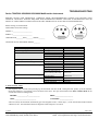
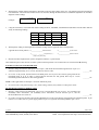
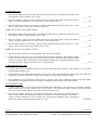
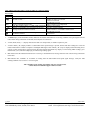
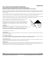
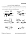
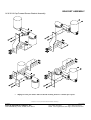
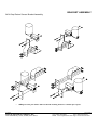
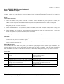
Sensor Placement. Determine where the Flow Sensor, or Flow Sensor-Pulsation Damper assembly is to be installed. Install the
sensor, or sensor-pulsation damper assembly so that the two fuel flow arrows, (
) or the, (IN and OUT) markings are on a
horizontal plane. All orientation arrows, (!) must be pointing up. The forward sensor or forward sensor-pulsation damper
assembly must be installed downstream of the primary filter. Do not install the sensor or either sensor assembly at a high point in
the fuel system. This could negatively impact system accuracy by trapping air. The fuel return line between the return sensors’
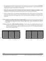
outlet port and fuel tank should be at least 12” long and have a 1 to 2” upward rise. This keeps the return sensor flooded,
improving accuracy. Place sensor assemblies in a protected location away from water spray.
Forward Sensor &
Pulsation Damper
Assembly
Return Sensor &
Pulsation Damper
Assembly
FloScan
Inlet
Outlet
FloScan
Inlet
Outlet
FloScan
233/ 236-1K & 2K
Forward Sensor
And Pulsation
Damper Assembly
Return Sensor
And Pulsation
Damper Assembly
FloScan
Outlet
Inlet
233/ 236-2K
Outlet
Inlet
201/ 231-1K & 2K, 235-2K
Inlet
FloScan
201/ 231/ 235-2K
Outlet
Outlet
Inlet
233C-10 & 233D-10 (Cummins PT Systems)
8/5/2003
FloScan Instrument Company, Inc.
3016 NE Blakeley Street, Seattle, WA 98105
ARROW UP
231-10 (Cummins PT Systems)
4001-325-00F
Tel: (206) 524-6625
Fax: (206) 523-4961
email: [email protected] http://www.floscan.com