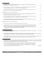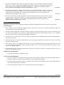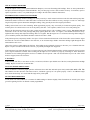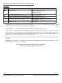
1
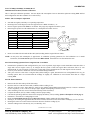
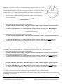
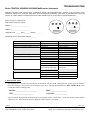
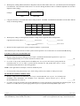
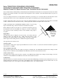
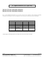
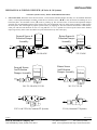
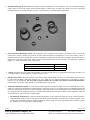
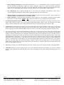
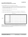
Installation / Troubleshooting Manual
MFI, Diesel, NMEA, In Line Injection K Series
with Magnetic Pick-up, AC Signal Generator,
or Alternator Pick-up Tachometer
This manual (part # 9000-020-04) applies to the following product part numbers:
1.
2.
3.
4.
5.
6.
7.
8.
9.
10.
11.
12.
13.
910M-231-2K
910M-BOS2K
910M0-2012K
910M0-2312K
91TM-235-2K
950M-201-2K
950M-231-2K
950M-BOS-2K
950M0-2012K
950M0-2312K
950M0-BOS2K
95TM-235-2K
95TM0-2352K
3/4/2004
FloScan Instrument Company, Inc.
3016 NE Blakeley Street, Seattle, WA 98105
9000-018-44
Tel: (206) 524-6625
Fax: (206) 523-4961
email: [email protected] http://www.floscan.com
CALIBRATION
Series 75/7600(0), 85/8600(0), 95/9600(0) M & I
Multifunction Instrument, Totalizer Calibration
This is a three-part calibration procedure. Part one adjusts idle consumption. Part two determines optimum cruising RPM and fuel
tank configuration. Part three calibrates for overall accuracy.
PART I: Idle Consumption Adjustment
•
•
•
•
Start and run engine(s) until they’re at operating temperature.
Referring to the switch diagram, rotate the Upper and Lower Black Switches to, “0”.
Increase engine speed to 1800 RPM for one minute. This purges any trapped air from the system.
Return engine speed to low idle and determine its’ consumption from Table 1 below.
Table 1
HP
100-400
400-750
750-1000
1000-1250
1250-1500
1500-2000
2000-3000
No Load Idle Consumption
Non-Turbo
w/Turbo
0.1-0.5 GPH, (1-2 LPH)
0.3-0.7 GPH, (2-3 LPH)
0.8 GPH, (3 LPH)
1.0 GPH, (3-4 LPH)
1.0 GPH, (4 LPH)
1.5 GPH, (5-6 LPH)
2.0 GPH, (7-8 LPH)
2.5 GPH, (9-10 LPH)
3.0 GPH, (11-12 LPH)
3.5 GPH, (13-14 LPH)
3.5 GPH, (13-14 LPH)
4.0 GPH, (15-16 LPH)
4.5 GPH, (17 LPH)
5.0 GPH, (18-19 LPH)
0 is the
reference
point
Turning switch
counter clockwise
0-6 will increase
the GPH, (LPH)
reading
D
C
E
F 0
1
9
7
2
B
A
8
Turning switch
clockwise from
3
0-5 will
the
4 decrease
GPH, (LPH)
reading
5
6
Lower BLACK Switch
•
Rotate Lower Black Switch until the idle GPH, (LPH) reading matches engine HP from Table 1.
NOTE: At this point, idle consumption is approximate. It establishes operating parameters for final calibration. On G model
instruments, the Green Switch replaces the Lower Black Switch. G Instruments were discontinued in 1999.
Part II: Determining Optimum Tank Configuration & Cruise RPM
•
•
•
Determine the optimum fuel tank configuration for your vessel. If possible, single engine vessels should draw and return fuel to a
single tank. On twin engine vessels, try to configure the fuel system so that each engine draws and returns fuel to its’ own
dedicated tank. If your twin engine vessel has only a single tank, equal consumption rates for both engines must be assumed.
Close any cross connect or limber line valves between tanks during calibration.
Take your vessel for a short cruise. Using the GPH, (LPH) reading as a guide, determine the best cruising RPM for the way you
normally operate. Don’t be concerned that the readings are slightly off. Calibration is most accurate when done at a single
cruising RPM.
Part III: Final Calibration
•
•
•
•
•
•
•
•
•
•
•
Return to the fuel dock and top off the fuel tank(s).
Reset the totalizer so that the GALLONS, (LITERS) window reading is zero.
Take the vessel for a cruise. Once underway, steam at your optimal cruising RPM, (Determined in Part II). Consume a minimum
of 20 to 30 gallons, (75 to 115 liters) of fuel per engine. Higher consumption gives better accuracy.
After consuming some fuel, return to the fuel dock and top off the fuel tank(s).
Compare the Gallons, (Liters) window reading to the fuel pump reading.
Calculate the percentage difference between the fuel pump & Gallons, (Liters) readings; (Refer to Examples I & II on page 2).
Determine if the totalizer is reading High or LOW.
Rotate the Upper Black Switch until the GALLONS, (Liters) window matches the fuel pump reading.
Starting at, “0” rotating the Upper BLACK Switch in a clockwise direction increases the Totalizer readings by 2% for each click.
Rotating the switch in a counter-clockwise direction decreases Totalizer readings by 2%.
Totalizer readings can be increased by 10%, or reduced by 20%.
(Continued on reverse side)
10/30/2002
FloScan Instrument Company, Inc.
3016 NE Blakeley Street, Seattle, WA 98105
7000-087-00F
Tel: (206) 524-6625
Fax: (206) 523-4961
email: [email protected] http://www.floscan.com
-2%
Example 1: Twin engine vessel with two, dedicated fuel tanks, (For single engine vessels with a
single tank, use either the Port or Starboard system calibration procedure in Example 1).
After steaming and returning to refuel. The Port tank took 89.7 gallons, (339.5 liters). Its’ totalizer
reads 94.2 gallons, (356..5 liters). The Starboard tank took 93.2 gallons, (352.8 liters) and its’
totalizer reads 87.9 gallons, (332.7 liters).
•
Using the formula, calculate the percentage difference between the Totalizer reading and
actual fuel consumption.
Difference in Gallons, (Liters)
x 100
Totalizer Reading
-4%
E
D
C
B
A
0%
F 0
2%
1
-6%
-8%
-10%
-12%
4%
2
6%
3
4 8%
5 10%
9
-14%
8
-16%
7
6
-20%
-18%
Upper BLACK switch
Port System Calibration
•
•
•
Find the difference between the totalizer and fuel pump readings:
[94.2 gallon, (356.5 liter) totalizer reading] – [89.7 gallon, (339.5 liter) pump reading] = 4.5 gallon, (170.3 liter) difference.
Determine percentage difference between readings:
[4.5 gallon, (17.0) liter difference] ÷ [94.2 gallon, (356.5 liter) totalizer reading] = .047 x 100 = 4.7% Higher difference.
To calibrate, rotate the Port MFI’s Upper Black Switch Counter-Clockwise to position E, reducing totalizer reading by 4%.
Starboard System Calibration
•
Find the difference between the totalizer and fuel pump readings:
[93.2 gallon, (24.4 liter) fuel pump reading] – [87.9 gallon, (332.7 liter) totalizer reading]= 5.3 gallon, (20.1 liter) difference.
•
Determine percentage difference between readings:
(5.3 gallon, (20.1) liter difference) ÷ (87.9 gallon, (332.7 liter) totalizer reading) = .060 x 100 = 6% Lower difference.
To calibrate, rotate the Starboard MFI’s Upper Black Switch Clockwise to position 3, increasing totalizer reading by 6%.
•
Example 2: Twin engine vessel with a single fuel tank.
Port System Calibration
After refueling the tank took 182.9 gallons, (692 liters). The Port Totalizer reads 94.2 gallons, (356.6 liters) and the Starboard reads
87.9 gallons, (332.7 liters). With a single tank, you must assume that each engine burned 91.5 gallons, (346.3 liters).
•
•
•
Find the difference between the totalizer and fuel pump readings:
[94.2 gallon, (356.5 liter) totalizer reading] – [91.5 gallon, (346.3 liter) assumed burn) = 2.7 gallon, (10.2 liter) difference.
Determine percentage difference between readings:
[2.7 gallon, (10.2 liter) difference) ÷ [94.2 gallon, (356.5 liter) totalizer reading) = .028 x 100 = 2.8% Higher difference.
To calibrate, rotate the Port MFI’s Upper Black Switch Counter-Clockwise to position F, reducing its’ totalizer reading by 2%.
Starboard System Calibration
•
•
•
Find the difference between the totalizer and fuel pump readings:
[91.5 gallon, (346.3 liter) assumed burn] - [87.9 gallon, (332.7 liter) totalizer reading] = 3.6 gallon, (13.6 liter) difference.
Determine percentage difference between readings:
[3.6 gallon, (13.6 liter) difference] ÷ [87.9 gallon, (332.7 liter) totalizer reading] = .041 x 100 = 4.1% Lower difference.
To calibrate, rotate the Starboard MFI’s Upper Black Switch Clockwise to position 2, increasing its’ totalizer reading by 4%.
This completes system calibration. The Instrument should be within 5% of actual consumption. Calibrating a second time should bring
it to within 3%, especially on twin engine, single tank vessels. Larger fuel burns increase calibration accuracy.
Drastically changing operating habits, (Changing from mostly cruising to mostly trolling) may affect totalizer accuracy. If this occurs,
re-calibration may be necessary.
10/30/2002
FloScan Instrument Company, Inc.
3016 NE Blakeley Street, Seattle, WA 98105
7000-087-00F
Tel: (206) 524-6625
Fax: (206) 523-4961
email: [email protected] http://www.floscan.com
TROUBLESHOOTING
Series 7500/7600 8500/8600 9500/9600 Multifunction Instrument
BEFORE CALLING FOR ASSISTANCE, COMPLETE THESE TROUBLESHOOTING CHECKS AND RECORD YOUR
FINDINGS. TECHNICAL SUPPORT REQUIRES THIS INFORMATION BEFORE A RETURN AUTHORIZATION WILL BE
ISSUED. IT TAKES ABOUT 20 MINUTES AND IS VERY IMPORTANT IN ANALYZING SYSTEM PROBLEMS.
Before starting, record Instrument
model number and switch settings.
MODEL # ________________________
0
0
BLACK
RED
F 0
1
A
16 15 14 13 12
UPPER BLACK________ RED________ GREEN________
7
6
5
BLACK
RED
0
4
GREEN
0
2
3
4
5
D
C
B
8
0
GREEN
E
SERIAL # ________________________
0
0
9
8 7
6
11 10 9
3 2 1
BACK OF INSTRUMENT
LOWER BLACK SWITCH
16 15 14 13 12 11 10 9
8 7 6 5 4 3 2 1
BACK OF INSTRUMENT
LOWER BLACK or RECESSED ARROW________
FAULT
PROBABLE CAUSE
SEE SECTION:
Blank LCD Display
No Back-Lighting
High or Low Totalizer reading. Over 10%.
Wiring
Wiring
Calibration
Incorrect flow sensor
Incorrect switch settings
Vacuum leak
Vacuum leak / Pulsations
Wiring
Sensor orientation
Wiring
Calibration
Continuity
In-synch with engine or
Glen Denning cable whip
Wiring /Instrument failure
Sensor Failure
Vacuum Leak
Incorrect switch settings
Sensor orientation
Sections II, III
Sections III
Calibration sheet
Operations sheet
Calibration sheet
Section IX
Sections VIII, IX, X
Sections II, V, VI
Installation sheet, Section IV
Installation sheet, Section II
Calibration sheet
Section VI
Fluctuating GPH Readings
No GPH or Totalizer Readings
High, Low or No Tachometer Reading
No Forward or Return Sensor Readings
High Forward or Return Sensor Readings
Section VII
Sections I, II, IV, V, VI
Section I, IV
Section IX
Calibration sheet
Section XI
I. DIAGNOSTIC TEST:
1.
Start engine(s). For 2 seconds after powering up, the Instrument will show all 8s. During this time, quickly cycle the TotalizerReset Switch from its’ run position to reset and back at least twice. This puts the Instrument into Show Switches Mode for 20
seconds. Record these readings below.
HOURS: ____________:_____________
RPM: ____________________
GPH: ________________________
GALLONS: _______________
After 20 seconds, the Instrument automatically goes into diagnostic mode. A minus sign (--) in the GALLONS window indicates
when this occurs. The Instrument remains in diagnostic mode until power is secured.
1/17/2002
FloScan Instrument Company, Inc.
3016 NE Blakeley Street, Seattle, WA 98105
7000-074-00C
Tel: (206) 524-6625
Fax: (206) 523-4961
email: [email protected] http://www.floscan.com
2.
With engine(s) running and the Instrument in diagnostic mode, the GPH window shows raw, (un-calibrated) fuel flow through the
Forward Sensor. The GALLONS window shows raw fuel flow through the Return Sensor. Calibration adjustments do not affect
diagnostic mode readings.
Example:
60.7
-59.3
GPH
3.
GALLONS
Using the chart below, record GPH and Gallon readings at IDLE, 1000 RPM, 1500 RPM and 1800 RPM. Circle S or F to indicate
steady or fluctuating readings.
GPH
4.
GALLONS
S
F
IDLE
S
F
S
F
1000
S
F
S
F
1500
S
F
S
F
1800
S
F
With engine(s) idling, record Engine Hour Window readings at these upper BLACK switch positions.
Upper BLACK switch position: 0 ______________Differential flow
2 ______________Feed K-Factor
1 _______ _______Temperature (C °)
3 ______________Return K-Factor
(Temp Comp units only)
5.
Measure fuel-line length between system components and draw a system sketch.
Turn Instrument power OFF, then ON to return system to normal operation. Do not touch the reset switch with all 8s showing.
II. SUPPLY VOLTAGE and GROUND TEST
1.
2.
Measure voltage between the RED power wire on pin 9, and the BLACK Instrument ground wire on pin 5. It
should read approximately 12 to 14 VDC, but not lower than 10 VDC.
__________VDC
If 12 VDC is not present, measure between the RED power wire on pin 9 and a known good ground in the
instrument panel. If 12 to 14 VDC is present between the Red wire and ground, there may be a loose
instrument ground connection or other wiring problem.
__________VDC
NOTE: Some applications use both pins 1 and 9 for Instrument power.
3.
If 12 to 14 VDC is not present in steps 1 or 2, check wiring, switches, fuse, and the 12 VDC power source.
III. LED BACK-LIGHTING WIRING TEST
1.
2.
Measure voltage between the ORANGE, wire on pin 4 and the BLACK wire on pin 5, for 75/7600(0) and
85/8600(0) series Instruments. On 95/9600(0) series Instruments, measure between pin 4, and the
BLACK/ORANGE wire on Pin 12.
__________VDC
If 12 VDC is not present, measure between the ORANGE wire on pin 4 and a known good ground in the instrument panel. If you
measure 12-14 VDC, there is a power supply problem to pin 4, or a ground connection problem to pins 5 or 12.
1/17/2002
FloScan Instrument Company, Inc.
3016 NE Blakeley Street, Seattle, WA 98105
7000-074-00C
Tel: (206) 524-6625
Fax: (206) 523-4961
email: [email protected] http://www.floscan.com
IV. SENSOR(S) TEST
1.
2.
3.
With engine(s) idling, measure and record voltage between the RED power and BLACK ground wires on the
Forward Sensor. Voltage should be 12 to 14 VDC.
___________VDC
Move the voltmeters’ negative lead to the WHITE signal wire. With engine idling, measure and record the
voltage. It should be approximately 5 to 7 VDC, about ½ of the reading in step 1.
___________VDC
Stop the engine while observing your voltmeter. Readings should fluctuate between a high of 9 to 12 VDC,
and a low of 0 to 4 VDC as the sensors’ turbine slows to a stop.
___________VDC
NOTE: This may not be seen on digital voltmeters.
4.
5.
6.
With engine(s) idling, measure and record voltage between the RED power and BLACK ground wires on the
Return Sensor, (If used). Voltage should be 12 to 14 VDC.
___________VDC
Move the voltmeters’ negative lead to the White (Signal) wire. With engine idling, measure and record the
voltage. It should be approximately 5 to 7 VDC, about ½ of the reading in step 1.
___________VDC
Stop the engine and observe the voltmeter. Voltage readings should fluctuate between a high of 9 to 12 VDC,
and a low of 0 to 4 VDC as the Sensors’ turbine slows to a stop.
___________VDC
NOTE: This may not be seen on digital voltmeters.
7.
The Sensor(s) may be defective if voltage readings in steps 3 & 5 remain constant.
___________VDC
8.
If signal voltages in steps 3 & 5 are ok, go to the backside of the MFI Instrument. With engine(s) running,
measure and record voltage across the Red & White, (Forward Sensor) and Red & Brown, (Return Sensor)
signal wires. The MFI voltage readings should match the Sensor readings. This verifies that the Sensors’ signal
is reaching the MFI. If voltage is not present, there is a wiring problem.
___________VDC
V. MFI SENSOR INPUT TEST
1.
Disconnect the WHITE and BROWN signal wires at the MFI Instrument harness. Connect a course thread, (½ -13) or similar
non-plated bolt to the Black wire.
2.
Run the WHITE wire up and down the bolt threads. This generates a pulse, which should make numbers in the GPH window start
counting up. The totalizer should also eventually start counting. Faster movements give higher readings.
3.
Run the BROWN wire up and down the bolt threads. This generates a pulse, which should make numbers in the GPH window
start counting up. The totalizer should also eventually start counting. Faster movements give higher readings.
VI. CONTINUITY TEST
1.
Continuity testing requires access to the back of the Instrument and an Ohmmeter. It verifies that wires are not broken, shorted to
ground, another wire, or to power. Before starting, secure all power, and disconnect the Molex connector from the Instrument.
This test checks the WHITE, BROWN, YELLOW, VIOLET, and BLACK wires.
2.
Disconnect the WHITE and BLACK wire harness conductors from the WHITE and BLACK Port Sensor
wires. Connect a jumper from the WHITE wiring harness conductor to a known good ground. At the Molex
connector, connect an Ohmmeter lead to its’ WHITE wire. Connect the other Ohmmeter lead to a known good
ground. The Ohmmeter should read approximately 0.1 to 3 Ω.
1/17/2002
FloScan Instrument Company, Inc.
3016 NE Blakeley Street, Seattle, WA 98105
____________
(Ohm Reading)
7000-074-00C
Tel: (206) 524-6625
Fax: (206) 523-4961
email: [email protected] http://www.floscan.com
3.
4.
5.
Disconnect the BROWN and BLACK wire harness conductors from the WHITE and BLACK Starboard
Sensor wires. Connect a jumper from the BROWN wiring harness conductor to a known good ground. At the
Molex connector, connect an Ohmmeter lead to its’ BROWN wire. Connect the other Ohmmeter lead to a
known good ground. The Ohmmeter should read approximately 0.1 to 3 Ω.
(Ohm Reading)
Disconnect the YELLOW wire harness conductor from the Port Tachometer Sender. Connect a jumper from
the YELLOW wiring harness conductor to a known good ground. At the Molex connector, connect an
Ohmmeter lead to its’ YELLOW wire. Connect the other Ohmmeter lead to a known good ground. The
Ohmmeter should read approximately 0.1 to 3Ω.
(Ohm Reading)
Disconnect the VIOLET wire harness conductor from the Starboard Tachometer Sender. Connect a jumper
from the VIOLET wiring harness conductor to a known good ground. At the Molex connector, connect an
Ohmmeter lead to its’ VIOLET wire. Connect the other Ohmmeter lead to a known good ground. The
Ohmmeter should read approximately 0.1 to 3Ω.
(Ohm Reading)
____________
____________
____________
VII. TACHOMETER PROBLEMS
Note: Refer to the engine owners’ manual, wiring diagram, installation, and calibration instructions for parts A, B, & C below.
A. NO READING.
1.
Check continuity of the YELLOW and VIOLET Tachometer signal wires, (Section VI). Verify that the tachometer signal wires
are connected at the correct signal output point.
2.
Disconnect either the YELLOW or VIOLET Tachometer signal wire from the Tachometer Sender. Connect an Ohmmeter to the
two sender wires and measure its’ resistance. AC Signal Generators should measure approximately 180 Ω, (±) 10%. Magnetic
Pick-ups can measure between 100 to 800 Ω depending on manufacturer.
3.
Next connect an AC Voltmeter to the sender wires. Both AC Signal Generator and Magnetic Pick-up senders should produce at
least several volts at idle.
4.
If the voltmeter reads “0” on an AC Signal Generator, it may not be properly attached to its drive port. Verify that its’ drive shaft
and tang are installed correctly.
5.
If the voltmeter reads, “0” on a Magnetic Pick-up sender, it may not be installed correctly. With engine stopped, loosen its’ lock
nut. Turn the sender clockwise until it bottoms out. Back the sender out 1/8th to 1/4th turn. Turn the engine over by hand, or slowly
jog it to verify adequate clearance.
6.
Engine alternators tend to be an inaccurate Tachometer signal source, especially at low Rpm’s. The engine may have to be revved
up before the Tachometer will read.
B. HIGH OR LOW READINGS.
1.
Verify that the Tachometer is calibrated correctly.
C. FLUCTUATING READINGS.
1.
Listen to your engine(s). If engine speed cycles up and down, (when idling or underway) the tachometer reading will follow.
This does not indicate a problem with the Tachometer, but may indicate engine problems.
2.
Verify that wiring connections are tight, clean and dry. Check continuity while shaking the wires. Ohm readings should be
near zero and remain steady while shaking.
3.
Verify that the tachometer signal wires are connected at the correct signal output point.
1/17/2002
FloScan Instrument Company, Inc.
3016 NE Blakeley Street, Seattle, WA 98105
7000-074-00C
Tel: (206) 524-6625
Fax: (206) 523-4961
email: [email protected] http://www.floscan.com
VIII. PULSATION PROBLEMS
A stiff anti-siphon valve(s) or miss-plumbed Pulsation Damper(s) can cause fluctuating GPH readings. These are most pronounced at
low Rpm’s and tend to disappear around mid throttle. They are annoying, but won’t affect totalizer accuracy. To eliminate, repair or
replace any defective valves, or re-plumb dampers according to the Fuel Flow Schematic Instructions.
IX. FINDING FUEL SYSTEM VACUUM LEAKS
Fluctuating GPH and High Totalizer Readings are usually caused by a small vacuum leak between the fuel tank and fuel pump inlet.
Fluctuations tend to be between 2 and 4 GPH. These vacuum leaks also affect totalizer accuracy, causing it to read 15 to 100% high.
Larger leaks produce greater fluctuations and higher readings. They generally do not affect engine performance.
Finding suction leaks can be time-consuming. When approached properly, they can usually be found and repaired quickly. Two
common places for suction leaks to occur are at the primary fuel filter - water separator, and/or a loose valve stem packing nut.
Remove the filter housing and coat all o-rings, gaskets and sealing surfaces with a medium to heavy grease, (Do not use oil) and
reassemble. Grease all valve stem packings and gently tighten gland nuts. Don’t over tighten, valve handles should turn freely.
Tighten all hose clamps and compression fittings. Don’t over tighten. Run the engine for 5 to 10 minutes observing GPH readings. If
you’ve found the problem, fluctuations should be reduced to less than ½ GPH.
If the problem persists, temporarily install a clear piece of fuel resistant hose downstream of the forward flow sensor. Run the engine
and watch for a stream of small bubbles in the clear hose, or an occasional larger bubble. Sometimes shining a light through the hose
makes bubbles easier to see.
Observe the clear hose while shaking the fuel lines. If the bubble stream continually increases or decreases you’ve found the leak area.
Repair or replace as needed. If this occurs one-time, you probably dislodged some trapped air.
If the leak hasn’t been found, the last step is to inspect each pipe joint. Thread sealant should be visiable around each joint. If not, that
joint is suspect and must be resealed. After resealing run the engine for a few minutes to purge any remaining air. There should now
be bubble free fuel running through the clear hose. If bubbles are still present a leak was missed. Recheck your work. After all the
leaks are stopped, remove the clear hose.
X. Fuel Filters
A dirty Primary fuel filter, or one that is too fine (1-25 micron) will draw vapor bubbles out of the fuel, causing fluctuations and high
readings. Replace it with a new 30-micron filter.
XI. FLOW SENSOR ORIENTATION
Sensor orientation is critical for proper operation. All Sensors have their inlet and outlet ports clearly marked (IN / OUT or Î Î).
This identifies fuel flow direction. The Sensor must be, “Plumbed” correctly for it to operate properly. There is an additional single
arrow on the Sensor body. It is crucial that this single arrow points up Ï.
XII. LOW RPM OPERATION
At idle, under a no load condition, it is common for GPH readings to fluctuate slightly. These fluctuations are caused by the engine
governor regulating fuel flow to maintain a steady engine RPM.
1/17/2002
FloScan Instrument Company, Inc.
3016 NE Blakeley Street, Seattle, WA 98105
7000-074-00C
Tel: (206) 524-6625
Fax: (206) 523-4961
email: [email protected] http://www.floscan.com
XIII. NMEA 0183 Input, MPG, (Nautical) Miles per Gallon Problems:
Error Codes
Display
OFF
Reason
No signal activity present on NMEA 0183 terminals
for four seconds
---
Receiving valid NMEA 0183 Version 1.5 or 2.0
message, speed message invalid.
Fuel flow reading below 0.1 GPH (LPH) (twin-both
engines). Valid NMEA 0183 speed message present.
Some pulsing activity present. No valid NMEA 0183
message received in last four seconds.
-0Er1
Er2
NMEA message detected.
“LCRMA” sentence.
Missing “GPRMC” or
Cause
GPS / LORAN-C OFF
NMEA OUTPUT not selected
Leads not connected
A & B leads reversed
GPS satellite reception is poor
GPS / LORAN-C in startup mode
Engine(s) not running
Fuel flow reading problem.
Leads connected to wrong source
GPS / LORAN-C set to NMEA 0180 or 0182
A & B leads reversed.
GPS / LORAN-C incompatible with NMEA 0183, ver.
1.5 or newer
1.
An OFF display in the GPH/MPG window indicates the FloScan Instrument isn’t receiving a NMEA 0183 speed signal from the
GPS. Check wiring connections to the GPS, and verify that it is turned on.
2.
A Dash, Dash, Dash, (- - -) display indicates the GPS is in startup mode, or satellite reception is poor.
3.
A Dash 0 Dash, (- 0 -) display indicates a valid NMEA 0183 speed message is present, but that fuel flow readings are so low the
FloScan Instrument is unable to compute a meaningful MPG figure. Dash 0 Dash, (- 0 -) may be displayed when motoring at low
speeds, or when slowing down. When slowing down the FloScan Instrument may display ever-increasing MPG readings, go to
Dash 0 Dash, (- 0 -) and start redisplaying ever-increasing readings again.
4.
Er1 indicates that the FloScan Instrument isn’t receiving a valid NMEA 0183 message from the GPS. Check wiring connections
to the GPS.
5.
Er2 indicates that, “GPRMC” or “LCRMA” is missing from the GPS NMEA 0183-speed signal message. Verify the GPS
sending a NMEA 0183 version 1.5 or newer signal.
This concludes system testing. If problems with your system persist,
contact FloScan Technical Support with test results
1/17/2002
FloScan Instrument Company, Inc.
3016 NE Blakeley Street, Seattle, WA 98105
7000-074-00C
Tel: (206) 524-6625
Fax: (206) 523-4961
email: [email protected] http://www.floscan.com
Lo-Flo Pulsation Damper Can Replacement
FloScan
233-041-00
MOUNT WITH ARROWS UP
Rubber Sealing
Washer
Aluminum Base
Forward Sensor
FloScan
233-041-00
MOUNT WITH ARROWS UP
Rubber Sealing
Washer
Aluminum Base
Return Sensor
1. Remove the old Pulsation Damper can. A Claw type oil filter wrench, or pipe wrench may be needed.
2. Put a coating of grease on both sides of the new Pulsation Dampers’ rubber sealing washer.
3. Clean the Aluminum base and put a coating of grease on the seal’s mating surface.
4. Place the new Pulsation Damper can on its Aluminum base. Turn until “Finger tight”.
5. Using a band type oil filter wrench, carefully rotate the can until tight, approximately ¾ of a turn past finger
tight.
• Position a strip of rubber, (Bicycle tube or rubber glove) between the wrench and can. Rubber increases
friction and protects the can. Use caution as over-tightening will buckle or collapse the can.
White Replacement K-Series Pulsation Damper Can P/N 233-041-00.
4/23/2003
FloScan Instrument Company, Inc.
3016 NE Blakeley Street, Seattle, WA 98105
7000-145-01
Tel: (206) 524-6625
Fax: (206) 523-4961
email: [email protected] http://www.floscan.com
Hi-Cap Pulsation Damper Can Replacement
FloScan
FloScan
233-041-00
233-041-00
MOUNT WITH ARROWS UP
MOUNT WITH ARROWS UP
Rubber Sealing
Washer
Rubber Sealing
Washer
Aluminum Base
Aluminum Base
FloScan
Return Sensor
Forward Sensor
1. Remove the old Pulsation Damper can. A Claw type oil filter wrench, or pipe wrench may be needed.
2. Put a coating of grease on both sides of the new Pulsation Dampers’ rubber sealing washer.
3. Clean the Aluminum base and put a coating of grease on the seal’s mating surface.
4. Place the new Pulsation Damper can on its Aluminum base. Turn until “Finger tight”.
5. Using a band type oil filter wrench, carefully rotate the can until tight, approximately ¾ of a turn past finger
tight.
• Position a strip of rubber, (Bicycle tube or rubber glove) between the wrench and can. Rubber increases
friction and protects the can. Use caution as over-tightening will buckle or collapse the can.
White Replacement K-Series Pulsation Damper Can P/N 233-041-00.
4/23/2003
FloScan Instrument Company, Inc.
3016 NE Blakeley Street, Seattle, WA 98105
7000-145-01
Tel: (206) 524-6625
Fax: (206) 523-4961
email: [email protected] http://www.floscan.com
!
INSTALLATION PLANNING
!
READ ME FIRST - Detailed Mechanical & Electrical Planning Saves Installation Hours!
FloScan K Series systems are not difficult to install. Installation requires only basic electrical & mechanical skills. With forethought
and planning, your system will be installed with few problems. Todd Walker, Yacht Electric Co., (954) 325-9091 regularly installs
FloScan K Series Twin Diesel Systems in about 10 hours. Difficult installations may take several hours longer.
I. Installation Preparation:
Review the pre-installation booklet, mechanical installation instructions, and survey your vessel. Determine where the Sensor(s),
Sensor Assemblies, Switches and Instruments are to be mounted. Place them at their approximate locations. Determine fitting size and
types required for each plumbing connection, (JIC, SAE, NPT, NPTF, or Hose Barb).
FloScan K-Series Hi-Cap Diesel Forward Sensor Assemblies have 1” Female NPT ports.
FloScan K-Series Hi-Cap Diesel Return Sensor Assemblies have 1” inlet and ½” outlet Female NPT ports.
FloScan Hi-Flo, (-10) Diesel and Gasoline Sensors have ½” Female NPT ports.
FloScan K-Series Lo-Flo Diesel and Gasoline System Components, (Sensors and Pulsation Dampers) have ¼” Female NPT ports.
Review the electrical installation instructions. Open and survey your vessels wire ways. Determine if it would be easier to run a 3conductor cable from each sensor to the instrument, or install a junction box, (J-Box) with terminal strip in the engine room. The JBox requires a 4-conductor cable from it to the instrument, and a 3-conductor cable from each sensor. Measure cable lengths from
sensor(s) to J-Box, (If used) to Instrument. Tachometers require a separate 2-conductor cable. If there’s an existing tachometer, its
signal wires can be used.
II. Mechanical Installation:
Install or mount the Sensor(s) or Sensor Assemblies, Instruments and Switches, (Reset, MPG).
III. Plumbing:
Most K Series and -10 installations do not require additional fuel hose. Mount the sensor(s) or sensor assemblies where they’re to be
installed. On installations using Fabric Braid A-1 Fuel Hose install the correct HB X MNPT fitting into each sensor or sensor
assembly. Always assemble fittings using a fuel proof pipe thread sealant. Never use Teflon Tape. Use a hose cutter or knife to cut
the fuel hose. Next install the hose onto the barb fittings. Hose should not be twisted, have adequate slack, an ample radius at all bends
and be supported at reasonable distances, approximately 2-4 feet. When clamping hose onto the barbs, use 2 narrow or 1 wide
stainless hose clamp on each hose end.
Wire Braid A-1 Aeroquip Type Fuel Hose or Hydraulic Hose: Mount the sensor(s) or sensor assemblies where they’re to be
installed. Mark the hose where it is to be cut. Remove hose and bring it to a hydraulic shop. Have them cut the hose and install hose
ends. Reinstall the hoses and install the correct fitting into each sensor or sensor assembly. Always assemble fittings using a fuel proof
pipe thread sealant. Never use Teflon Tape. Hoses should not be twisted, have adequate slack, an ample radius at all bends and be
adequately supported at reasonable distances, approximately 2-4 feet. AP-50 copper sealing washers, (Connie Seals) or Flaretite seals
may be required to seal JIC & SAE fittings.
IV. Electrical Installation:
Run cables between Sensor(s), J-Box, (If used) and Instrument(s). Cables must be adequately supported at reasonable distances,
approximately 2-4 feet.
Wire Terminations—Referring to the wiring diagram. Connect Sensor, Instrument and Switches to their respective wires with crimp
type butt or ring connectors. Always cover connectors and wire ends with heat shrink tubing.
5/14/2004
FloScan Instrument Company, Inc.
3016 NE Blakeley Street, Seattle, WA 98105
4001-386-02B
Tel: (206) 524-6625
Fax: (206) 523-4961
email: [email protected] http://www.floscan.com
V. Pre-Startup:
Prime the fuel system. If you have an electric priming or boost pump, circulate fuel for 10 minutes while checking for leaks. If not, use
the engines manual pump. Before starting, open the lift pumps’ outlet fitting slightly. Before start-up, verify that all fuel system
fittings are tight.
VI. System Start-Up:
Start and run your engines. Look for leaks and other installation problems. If system is not operating properly refer to the
Troubleshooting Instructions and correct any deficiencies.
VII. Calibration:
When system is running properly, refer to the calibration instructions and calibrate your system. If installed properly, initial calibration
takes less than 1 hour. After consuming some fuel, final calibration should only take a few minutes.
USCG approved fuel hose with either fabric or wire reinforcing braid meet the following standards:
Hose Marking
USCG Type A-1
USCG Type A-2
USCG Type B-1
USCG Type B-2
Permeation Rating
100g/m²/24hrs.
300g/m²/24hrs.
100g/m²/24hrs.
300g/m²/24hrs.
2½ Minute Fire Test
Required
Required
Not Required
Not Required
Table I
5/14/2004
FloScan Instrument Company, Inc.
3016 NE Blakeley Street, Seattle, WA 98105
4001-386-02B
Tel: (206) 524-6625
Fax: (206) 523-4961
email: [email protected] http://www.floscan.com
Installation Do’s & Don’ts
Do
Don’t
Use a Fuel Proof Pipe Thread Sealant when
assembling fittings into fuel system components,
(Locktite PST, Leak-Lock, or equivalent).
Never use Teflon Tape!
Don’t use Push-Lok, or Barb-Tite fittings.
Use thin wall, low pressure, full flow type NPT or
Avoid using JIC or SAE swivel fittings. If used
NPTF hose barb fittings.
always install copper conical sealing washers,
(Connie seals) or fitting seals on fittings.
Double clamp all hose barb fittings.
Avoid using 90º elbow fittings.
Install Sensor(s) at a low point in the fuel system, as
far from the engine as practical. Fuel must travel, If possible, avoid bolting or mounting sensor(s)
“Up-hill” slightly after leaving the sensor. Verify directly onto the engine.
correct orientation and fuel flow direction.
Install Forward Sensors on the Fuel Pumps’ Inlet or If on the Pressure Side, Limit Sensor System
Vacuum side, and not on the pressure side.
Operating Pressure to 20 PSI or Less.
Always use 30-micron primary filters.
Avoid 2 or 5 micron primary filters.
Wire with Shielded Cable. Use a dedicated shielded Never use unshielded wires on Magnetic Pickup
pair for Magnetic Pickup Tachometer Senders.
Tachometer Senders.
Connect all, “Ground” wires to a Ground Buss, or
directly to the Battery’s Negative Terminal. Connect Never connect Instrument or Sensor “Ground”
wires to the hull, engine block, or other
or, “Ground” wire shields to the engine block.
machinery.
On Instruments with a GPS interface, connect
Do not connect FloScan’s Data (–) to the GPS
FloScan’s Data (+) to the GPS signal output.
Data (–).
Connect Data (–) to the GPS signal ground.
Always use non-illuminated switches for Totalizer
Reset, Port/Starboard Select, Hours/Synch, and
GPH/MPG.
5/14/2004
FloScan Instrument Company, Inc.
3016 NE Blakeley Street, Seattle, WA 98105
Never use illuminated, or back-lit switches.
4001-386-02B
Tel: (206) 524-6625
Fax: (206) 523-4961
email: [email protected] http://www.floscan.com
OPERATION
Series 7500(0)/7600(0), 8500(0)/8600(0), 9500(0)/9600(0)
Temperature Compensated, & Non-Temperature Compensated
Magnetic Pickup & AC Signal Generator Type Tachometer Sender Instruments
Series 7500(0)/7600(0), 8500(0)/8600(0), 9500(0)/9600(0) Diesel Multifunction Instruments use a microprocessor-based, non-volatile
Random Access Memory (RAM) to store engine hours and gallons of fuel consumed. Non-volatile RAM requires no power for
memory retention.
All “8”s are displayed for the first 3 seconds when the instrument is powered up. For 1 second after that, the instrument shows switch
positions and software version. After completing its start-up sequence, the instrument goes into normal operating mode.
If supply voltage drops below 10V DC for any reason, the instrument displays a row of decimals across the bottom of the RPM
window. This does not affect instrument accuracy. Stored engine hours and fuel consumption data will not be lost.
Liquid crystal displays have an OPTIMUM VIEWING ANGLE. If your viewing
angle is outside this range, contrast will decrease and numbers may flicker.
Before drilling any holes in your dash, it’s a good idea to temporarily power up
the instrument (+12V DC to the RED wire on plug #9, 12V DC to the BLACK
wire on plug #5) before installing it and see if the intended viewing angle is
acceptable.
Engine Hours
The engine hours meter is shipped at or near zero hours. It accurately tracks the
number of hours your engine has run. Unlike most hour meters, it only
accumulates time when the engine is actually running. If the meter is turned ON,
but the engine is NOT running, NO time is added to the engine hour display.
Optimum
viewing
angle
The engine hour meter cannot be reset.
Tachometer (RPM)
The Tachometer window shows engine speed in RPM and is accurate to within ± 1% (belt driven alternator tachometer signals are
only accurate to ± 50 RPM).
Flow Consumption (GPH, LPH)
The GPH/LPH window shows the rate at which your engine is consuming fuel. The GPH/LPH and Gallons/Liters readings will both
change if the flow calibration switch (UPPER BLACK SWITCH) on the back of the instrument is turned.
Totalizer (Gallons, Liters)
The Gallons/Liters window shows total fuel consumed. The GPH/LPH and Gallons/Liters readings will both change if the flow
calibration switch (UPPER BLACK SWITCH) on the back of the instrument is turned.
Totalizer Reset
When the totalizer-reset switch is turned ON (Closed), the GALLONS/LITERS display will flash for ten seconds, then reset to zero.
Flashing indicates the instrument is in reset mode. If the RESET switch is turned OFF (Opened), before the totalizer reads “0.0”, the
instrument will NOT reset. If you neglect to turn OFF the RESET switch, “0.0” continues to flash.
4/11/2001
FloScan Instrument Company, Inc.
3016 NE Blakeley Street, Seattle, WA 98105
7000-065-00G
Tel: (206) 524-6625
Fax: (206) 523-4961
email: [email protected] http://www.floscan.com
AC Signal Generator, (G) Type Only
750G/760G, 75TG/76TG, 750G0/760G0, 75TG0/76TG0
850G/860G, 85TG/86TG, 850G0/860G0, 85TG0/86TG0
950G/960G, 95TG/96TG, 950G0/960G0, 95TG0/96TG0
Type “G” Diesel Multifunction Instruments are preset for the correct flow sensor combination. Before installing the instrument,
verify that the switch settings are correct for your application. Flow Sensor types are coded as part of your kit model number.
Recessed “Arrow” Rotary Switch Settings
Switch Position
0
1
2
3
4
5
6
7
Flow Sensor
CAT 265/265
RTY 265/201
265/231
231/231
201/201
BOS 231/201
All 235/236 &
233 B-C, C-D, D-E, E-F,
and combinations
233A/233A
Switch Position
8
9
A
B
C
D
E
F
Flow Sensor
233B/233B
233C/233C
233D/233D
233E/233E
233F/233F
Cummins 231*
Cummins 233C*
Cummins 233D*
*Cummins Engines with PT pump injection system using one flow sensor in the feed line to the engine.
4/11/2001
FloScan Instrument Company, Inc.
3016 NE Blakeley Street, Seattle, WA 98105
7000-065-00G
Tel: (206) 524-6625
Fax: (206) 523-4961
email: [email protected] http://www.floscan.com
INSTALLATION
MECHANICAL & WIRING OVERVIEW, (K Series & -10 Systems)
To Ensure System Accuracy, Follow All Installation Instructions.
•
Sensor Placement. Determine where the Flow Sensor, or Flow Sensor-Pulsation Damper assembly is to be installed. Install the
sensor, or sensor-pulsation damper assembly so that the two fuel flow arrows, (Î Î) or the, (IN and OUT) markings are on a
horizontal plane. All orientation arrows, (Ï) must be pointing up. The forward sensor or forward sensor-pulsation damper
assembly must be installed downstream of the primary filter. Do not install the sensor or either sensor assembly at a high point in
the fuel system. This could negatively impact system accuracy by trapping air. The fuel return line between the return sensors’
outlet port and fuel tank should be at least 12” long and have a 1 to 2” upward rise. This keeps the return sensor flooded,
improving accuracy. Place sensor assemblies in a protected location away from water spray.
Forward Sensor &
Pulsation Damper
Assembly
Return Sensor &
Pulsation Damper
Assembly
FloScan
Inlet
Outlet
FloScan
Forward Sensor
And Pulsation
Damper Assembly
Inlet
Outlet
233/ 236-1K & 2K
Outlet
Inlet
233/ 236-2K
Return Sensor
And Pulsation
Damper Assembly
FloScan
FloScan
Outlet
Inlet
201/ 231-1K & 2K, 235-2K
Inlet
FloScan
201/ 231/ 235-2K
Outlet
Outlet
Inlet
233C-10 & 233D-10 (Cummins PT Systems)
8/5/2003
FloScan Instrument Company, Inc.
3016 NE Blakeley Street, Seattle, WA 98105
ARROW UP
231-10 (Cummins PT Systems)
4001-325-00F
Tel: (206) 524-6625
Fax: (206) 523-4961
email: [email protected] http://www.floscan.com
•
Determine fitting type & size. Minimize the number of elbows and fittings. If swivel fittings are used, (JIC or SAE) their mating
surfaces must be sealed with Copper Conical Sealing Washer, (Connie Seals) or fitting seals. Fitting seals may be purchased
through Fittings Inc. in Seattle, WA (206) 767-4670, 1-800-552-0632, or a local hydraulic supply house.
•
Select Instrument Mounting Location. The instruments’ face is waterproof and a gasket is provided to seal its bezel to the
control panel. Choose a location away from the compass. Install 65/6600 series instruments 12” away from compass. Choose a
shaded location since direct sunlight may cause the LCD display to temporarily turn. This does not damage the LCD, but makes it
impossible to read until cooling down. Make a cutout in the instrument panel for the instrument. The instruments’ maximum
depth is 3 ½” minus the thickness of the console panel.
Instrument Series
6500/6600
7500/7600, 8500/8600, 9500/9600, TwinScan
•
Cutout Size
3 1/16”
3 3/8”
Wiring. Determine wiring run length and the number of switches needed, (always use good quality marine grade switches). Use
18 AWG conductors on runs under 50’. 16 AWG for runs over 50’.
•
Run & Connect Wires. Wire one system at a time. Always begin with the Black, “Ground” wires. Each Black sensor wire must
be connected to the Black, “Instrument Ground” wire. Use a single wire to connect these Black wires to the battery’s negative
terminal, or to the ground buss. For the system to operate properly the, “Ground” wires must be connected in this manner.
Connect other wires per the wiring diagram. Leave the RED, power wire for last.
•
Tachometer Installation Options. 75’7600, 85/8600, and 95/9600 series tachometers require one or two additional wires. If your
engine isn’t equipped with a tachometer sender determine which type it requires, (AC Signal Generator or Magnetic Pickup) and
install one. Some engine alternators produce a tachometer signal and can be used as the tachometer sender. Mechanically driven
AC signal generators and magnetic pickups are available from FloScan and most marine dealers. Hewitt, Motorola, VDO and
Stewart Warner are some of the more common brands.
1.
Keep Existing Tachometer(s). Connect the FloScan tachometers’ Yellow and Violet signal wires to the existing tachometer.
If the tachometer sender wire(s) are not marked, trace them from the tachometer sender up to the existing tachometer. If one
sender lead is grounded, connect the FloScan tachometers Yellow signal wire to the ungrounded lead or terminal. Connect
the VIOLET wire to a Ground Buss, or Battery Minus.
8/5/2003
FloScan Instrument Company, Inc.
3016 NE Blakeley Street, Seattle, WA 98105
4001-325-00F
Tel: (206) 524-6625
Fax: (206) 523-4961
email: [email protected] http://www.floscan.com
2.
Replace Existing Tachometer(s). FloScan MFI instruments have a 3 3/8” outside diameter. This is a common size and fits
into most instrument mounting holes. Identify the engines’ tachometer sender wires. Connect the FloScan tachometers’
Yellow and Violet signal wires to the sender wires. If one sender lead is grounded, connect the FloScan tachometers Yellow
signal wire to the ungrounded lead or terminal. Connect the VIOLET wire to a Ground Buss, or Battery Minus.
3.
New Tachometer(s). Run a dedicated shielded pair of wires between the instrument and tachometer sender, (This is
especially important with Magnetic Pickup senders). Ground the shield only in the engine room.
•
Magnetic Pickup & AC Signal Generator Tachometer Senders: Connect the FloScan tachometers’ Yellow signal wire to
one sender terminal. Connect the Violet wire to the other terminal.
Engine Alternators: Connect the FloScan tachometers Yellow signal wire to the alternators’ tachometer output terminal.
This terminal is usually marked as TACH, or SIG. Connect the VIOLET wire to a Ground Buss, or Battery Minus.
•
•
Pre-Startup & Installation Check. Prime the fuel system. If you have an electric priming or boost pump, circulate fuel for 10
minutes while checking for leaks. If not, use the engines manual pump. Before starting, “Crack” the lift pumps’ outlet fitting
slightly. Continue pumping until system is fully primed. Before start-up verify that all fuel system fittings are tight.
•
System Start-Up. Start and run your engines. Survey the installation for leaks and other problems. If the system is not operating
properly refer to the Troubleshooting Instructions and correct any deficiencies. When the engine reaches operating temperature
increase engine speed to about 1500-2000 RPM. Letting it run for five or ten minute’s helps purge residual air from the system.
•
Any vacuum leaks between the fuel tank and lift pump will allow air to be drawn into the system. These leaks cause high and/or
fluctuating GPH readings. Only severe leaks affect engine performance, but all leaks affect sensor performance and instrument
readings. Vacuum or suction leaks occur at improperly sealed primary filters, loose packing nuts on cross over & shut off valves
and improperly sealed fittings. Vacuum leaks can also occur from corroded copper fuel lines and chaffed fuel hose, (where it rubs
against bulkheads or engine parts). To verify that a suction leak is present, temporarily insert a clear piece of fuel resistant tubing
downstream of the Forward Sensors’ outlet. Observe the clear hose for at least two minutes looking for bubbles. Bubbles can
appear as a constant stream of small bubbles, or as an occasional larger bubble. Tighten all possible leak sources, grease primary
filter seals and install fitting seals on JIC/SAE fittings. Continue to observe the clear tubing until it runs clear without any
bubbles. Flex or wiggle rubber hose sections while observing the clear tubing. If bubble volume increases inspect the hose and
check its fittings. Repair as necessary.
•
When idling in neutral, (No Load) GPH fluctuations can also be caused by the governor trying to maintain a steady engine RPM.
•
Calibration. When the system is running properly, refer to the calibration instructions and calibrate your system. If installed
properly, initial calibration takes much less than 1 hour. After consuming some fuel, final calibration should only take a few
minutes.
8/5/2003
FloScan Instrument Company, Inc.
3016 NE Blakeley Street, Seattle, WA 98105
4001-325-00F
Tel: (206) 524-6625
Fax: (206) 523-4961
email: [email protected] http://www.floscan.com
INSTALLATION
Fuel Flow Schematic - Low Flow Diesel Systems (BOS, 201, 231 & 235-2K)
OUT
30 Micron
or Coarser
Filter
Forward Sensor
And Pulsation
Damper Assembly
OUT
IN
IN
**
Bottom view of Pulsation Damper
FloScan
Engine
Return Fuel
Cooler
**
Return Sensor
And Pulsation
Damper Assembly
Tank
FloScan
**
Fuel Flow Direction
*Caution: Diesel System Components are not designed for use on Gasoline Fuel Systems.
FloScan Sensor & Pulsation Damper Plumbing Guidelines:
1. Install flow sensor & pulsation damper assemblies with their orientation arrows pointing UP Ï. Fuel must
enter through the port marked IN, or with an inward pointing arrow, (ÎÍ) and exit through the port
marked OUT, or with an outward pointing arrow, (ÍÎ). Install the sensor – pulsation damper assembly as
far from the engine as practical. Maximizing fuel line length between engine and sensor – pulsation damper
assembly improves instrument accuracy. Pipe plugs are provided to block unused ports. Refer to Pulsation
Damper ** Bottom View.
2. Maintaining high flow velocities through the fuel lines minimizes sensor oscillations. Use the smallest
approved fuel line diameter for your engine, especially on the return line. Consult the engine owners’
manual for more information. To insure that the return sensor remains flooded, install the return sensor –
pulsation damper assembly at a low point in the system. Fuel should travel “Up-Hill” upon exiting the return
sensor.
3. Flow sensors must always be installed downstream of a filter or debris screen (no finer than 30 micron).
Particles larger than 1200 microns may jam the sensors’ rotor and cause it to fail.
4/23/2003
FloScan Instrument Company, Inc.
3016 NE Blakeley Street, Seattle, WA 98105
4001-309-02
Tel: (206) 524-6625
Fax: (206) 523-4961
email: [email protected] http://www.floscan.com
FloScan Low Flow 2K Diesel System Kits
Forward Flow
Return Flow
KIT
Sensor
Sensor
TYPE
201
201
201-2K
231
201
BOS-2K
231
231
231-2K
*235
*235
*235-2K
4. Flow sensor model numbers are molded into the colored plastic wire cap. Sensors are shipped in matched
pairs. They must not be mixed on twin engine installations. Match codes are identified by a single standalone letter stamped into the sensor body, or from a colored sticker.
5. Model *235 sensors are temperature compensated and stamped with their Instruments serial number, xxxxF
(Forward), xxxxR (Return). *235-2K Temp-Comp sensor kits are precisely calibrated and matched to each
instrument. Sensors are labeled FORWARD and RETURN and must be installed in these positions for
proper operation. The instrument head serial number must match the flow sensor(s) serial number.
6. If there’s a shut-off valve in the return line, do not operate the engine with it closed. Fuel system pressure
could exceed the system working pressure of 40 PSI, and may cause a catastrophic system failure. You
should either tag the valve so the engine will not run when it is closed for maintenance, or bypass it with a
relief valve.
NOTE: Minimize the number of 90º elbows and pipe fittings. Excessive use may create a high vacuum, fuel
restricting, pressure drop across the forward part of the fuel system. Refer to the engine owners’ manual
for maximum fuel pump inlet vacuum. A vacuum gauge can be used to confirm that the system is within
limits.
CAUTION: DO NOT OVER TIGHTEN FITTINGS. Torque sensor and pulsation damper pipe thread
fittings to a maximum of 15 ft.-lb. (180 inch-lb.), or 2 full turns past hand tight, whichever comes
first. Leak Lock pipe thread sealant is provided with your system. Use it on all pipe thread fittings.
DO NOT USE TEFLON TAPE.
4/23/2003
FloScan Instrument Company, Inc.
3016 NE Blakeley Street, Seattle, WA 98105
4001-309-02
Tel: (206) 524-6625
Fax: (206) 523-4961
email: [email protected] http://www.floscan.com
INSTALLATION
Series 9500/9600 Multifunction Instrument
Diesel - NMEA 0183 Input
This unit conforms to NMEA 183, Version 1.5 and 2.0 interface standards and requires a message that includes “GPRMC” or
“LCRMA”. Check your owners manual to verify your GPS / LORAN-C includes this information. To insure an easy trouble free
installation, read all instructions before starting
Wiring:
NMEA 0183 Connections:
1. Refer to the electrical wiring section of the GPS / LORAN-C Owner’s Manual for the proper procedure to connect your
GPS/LORAN-C to NMEA 183 devices. Use shielded wire between instruments and ground the shield ONLY at the GPS /
LORAN-C (sender end), not at the FloScan instrument end (receiver end). The shield is not to be used as a ground path.
2. Connect the WHITE/ORANGE wire (terminal #15, FloScan instrument) to the NMEA “A” (BNC center terminal) terminal
coming from your GPS / LORAN-C instrument.
3. Connect the GREEN/BLACK wire (terminal #7, FloScan instrument) to the NMEA “B” (BNC shield) terminal coming from
your GPS / LORAN-C instrument.
4. Connect the GRAY wire (terminal #2, FloScan instrument) to one terminal of a single pole, single throw switch. Connect the
BLACK wire (terminal #13, FloScan instrument) to the other terminal.
5. For single engine installations, the RED wire (terminal #1) is not used and should be taped off.
Calibration:
1. See your GPS / LORAN-C owners manual and set output for NMEA 0183. Speed is always sent as speed over ground in knots
no matter what units your GPS / LORAN-C displays.
2. Fuel flow rate used in the MPG calculation is automatically done when the totalizer(s) are calibrated. To calibrate, see the
Totalizer calibration instruction page.
MPG/GPH Operation:
With the MPG/GPH switch in the OFF position, your instrument displays engine fuel flow (in twin engine installations, each
instrument displays fuel rate and total consumption only for the engine on which it is installed). In the ON position, fuel mileage
(speed over ground in Knots /all fuel being consumed) is shown as “0.00 ” to “9.99 ”, then “10.0 ” to “99.9 ”. You must
have valid NMEA 0183 speed and a total flow rate of at least 0.1 GPH (LPH) to display fuel mileage or you receive an error code:
Error Codes:
Display
OFF
- - -0 Er1
Er2
Reason
No signal activity present on NMEA 0183 terminals for four
seconds
Receiving valid NMEA 0183 Version 1.5 or 2.0 message,
speed message invalid.
Fuel flow reading below 0.1 GPH (LPH) (twin-both
engines). Valid NMEA 0183 speed message present.
Some pulsing activity present. No valid NMEA 0183
message received in last four seconds.
NMEA message detected. Missing “GPRMC” or “LCRMA”
sentence.
7/23/1998
FloScan Instrument Company, Inc.
3016 NE Blakeley Street, Seattle, WA 98105
Cause
GPS / LORAN-C OFF
NMEA OUTPUT not selected
Leads not connected
A & B leads reversed
GPS satellite reception is poor
GPS / LORAN-C in startup mode
Engine(s) not running
Fuel flow reading problem.
Leads connected to wrong source
GPS / LORAN-C set to NMEA 0180 or 0182
A & B leads reversed.
GPS / LORAN-C incompatible with NMEA 0183, ver. 1.5 or
newer
9000-011-00
Tel: (206) 524-6625
Fax: (206) 523-4961
email: [email protected] http://www.floscan.com
During normal vessel operation, adjusting engine RPM to your maximum MPG (MPL) reading maximizes your fuel mileage. Vessel
trim, load, adjustment of trim tabs water currents and weather conditions also affect your fuel consumption. For similar operating
conditions, dramatic changes in MPG (MPL) readings indicate possible mechanical malfunction or excessive bottom fouling and
should be investigated.
Your current MPG (MPL) and GALLONS (LITERS) readings allow you to quickly and easily estimate your current maximum
cruising radius. For safety, allow a margin of error when calculating your next fuel stop.
7/23/1998
FloScan Instrument Company, Inc.
3016 NE Blakeley Street, Seattle, WA 98105
9000-011-00
Tel: (206) 524-6625
Fax: (206) 523-4961
email: [email protected] http://www.floscan.com
ELECTRICAL
Series 5500(0)/56100/5800(0)/6500(0) CruiseMaster,
All Multi Function Instruments, & TwinScan®
SET UP
Wire & Switches: Use 18 AWG stranded wire on runs under 50’. For runs over 50’ use 16 AWG, (Shielded wire is recommended for
all Diesel systems, and suggested for Inboard & I/O gasoline systems. Always, “Ground” wire shield or shield drain wire in the
engine room by connecting it to the bonding system, or engine block). The double wiring harness for twin engine Pulse/NMEA Diesel
installations is included in all, (97/9800(0)) kits. FloScan suggests using J-Boxes, Terminal Blocks, and three conductor cables
between the sensors and instrument to make wiring easier.
Install Single Pole Single Throw (SPST) switches for Totalizer Reset, Port–Starboard Select, Engine Hours / Synchronizer, and GPH /
MPG, (switches are not included in kit). To determine which switch types are required for your system, refer to the table below. All
instruments except TwinScan Tachometers require a totalizer reset switch.
SYSTEM
2500
5500
5800
6500/6600
ALL 7XXX or 8XXX MFI
All 9XXX MFI
TwinScan GPH
TwinScan Tach
NA = Not Applicable
TOTALIZER RESET
SPST or Momentary ON
SPST or Momentary OFF
SPST or Momentary OFF
SPST or Momentary OFF
SPST or Momentary ON
SPST or Momentary ON
SPST or Momentary ON
NA
PORT/STBD (Twin
Systems)
SPST
SPST
NA
SPST Twin
Cummins (PT) only
SPST
SPST
NA
NA
HOURS/
SYNCH
NA
NA
NA
NA
GPH/
MPG
NA
NA
NA
NA
MPG/
SYNCH
NA
NA
NA
NA
SPST
SPST
NA
NA
NA
SPST
NA
NA
NA
NA
SPST w/ both
GPH & Tach
Grounding: Each Black sensor wire must be connected directly to the Black, “Instrument Ground” wire. Use a single wire to connect
the Black wire junction to the battery’s negative terminal, or a ground buss.
Power: FloScan Instruments & sensors operate on 9 to 12 VDC. Voltages exceeding 16 VDC will damage the equipment. 24 & 32
VDC systems must be reduced to 12 VDC. Two different types of voltage reducers are available through FloScan.
CONNECT THE WIRES
Installation: Connect wires one at a time and Install heat shrink before proceeding to
the next wire, (refer to wiring diagram). Connect ground wires first, (BLACK
instrument ground wire to the BLACK sensor wires. Connect this junction to the
battery’s negative terminal or the ground buss). Connect all other wires leaving the
Red power wires for last to prevent short circuits during the installation.
Splicing: Splice or join individual wires per the diagram. Slide heat shrink tubing over
the splices to prevent shorts. Do not seal splices until the installation is finished and
has been tested.
1. Slide heat shrink tubing
over one wire.
2. Insert wire ends into butt splice.
3. Crimp butt splice.
4. Slide heat shrink tubing
over butt splice.
HEAT
5. Apply heat.
An adequate number of crimp-on connectors and heat-shrink tubing are included with
system. The heat-shrink is a special type that will bond to wire insulation and make a
watertight connection. See diagram for proper tubing application. Crimp-on connectors are sized for 18 or 20 gauge stranded wire.
FINAL ACTIONS
Check Electrical Installation: Test all connections. Support and secure all dangling wires. Start engine and calibrate system.
9/19/2003
FloScan Instrument Company, Inc.
3016 NE Blakeley Street, Seattle, WA 98105
4001-100-00H
Tel: (206) 524-6625
Fax: (206) 523-4961
email: [email protected] http://www.floscan.com
WIRING DIAGRAM
Series 9500/9600 Diesel Multifunction Instrument - NMEA 0183 Input
Instrument Connection Harness
FUNCTION
PIN #
FUNCTION
RED + 12VDC Twin applications
9
RED + 12VDC
GREY GPH/MPH select switch
10
GREEN Totalizer Reset
WHITE/RED + pulse in
11
not connected
ORANGE Illumination + 12VDC
12
BLACK/ORANGE Illumination ground
BLACK Instrument Ground
13
BLACK switches ground
WHITE flow sensor
14
BROWN not connected
GREEN/BLACK DATA (-) NMEA “B”
15
WHITE/ORANGE DATA (+)
YELLOW tachometer pick-up
16
VIOLET tachometer pick-up
PIN #
1
2
3
4
5
6
7
8
0
0
BLACK
0
RED
E
GREEN
F 0
1
2
D
C
B
3
4
5
A
9
8 7
6
16 15 14 13 12 11 10
9
2
1
8
7
6
5
4
3
BACK OF INSTRUMENT
Single Sensor Installations
7
CABLE
1/2 amp fuse
15
To Ignition Switch
(Key ON = + 12VDC)
RED
9
WHITE
6
4
BLACK
5
12
GREEN/BLACK
DATA (-) NMEA "B"
***Connect to GPS Signal Ground or Battery (-)
WHITE/ORANGE DATA (+) NMEA "A"
***Connect to GPS Signal Output
***See NMEA 0183 Input Installation Sheet
WHITE/RED
3
* Twin installations, see wiring
(+) Pulse In
diagram sheet 9000-016-00
To + Panel Illumination
+ 12VDC
ORANGE
To Illumination ground
BLACK/ORANGE
Magnetic Pick-up
YELLOW
8
16
Battery (-) buss
R
R
B
BLACK
B
W
CABLE
B
W
Flow
Sensor
WHITE
10
GREEN
BLACK
13
Totalizer
Reset Switch
(momentary ON)
12/18/2003
FloScan Instrument Company, Inc.
3016 NE Blakeley Street, Seattle, WA 98105
GREY
GPH/MPG Select switch
*
AC MECHANICAL GENERATOR
YELLOW
8
RED
VIOLET
*
VIOLET
2
16
* Pick-ups are non-polarity signals
9000-014-00C
Tel: (206) 524-6625
Fax: (206) 523-4961
email: [email protected] http://www.floscan.com
Instrument Connection Harness
FUNCTION
PIN #
FUNCTION
RED + 12VDC (Twin applications)
9
RED + 12VDC
GREY GPH/MPH select switch
10
GREEN Totalizer Reset
WHITE/RED + pulse in
11
not connected
ORANGE Illumination + 12VDC
12
BLACK/ORANGE Illumination ground
BLACK Instrument Ground
13
BLACK switches ground
WHITE forward flow sensor
14
BROWN return flow sensor
GREEN/BLACK DATA (-)
15
WHITE/ORANGE DATA (+) NMEA “A”
YELLOW tachometer pick-up
16
VIOLET tachometer pick-up
PIN #
1
2
3
4
5
6
7
8
0
0
BLACK
0
RED
GREEN
F 0
E
1
2
D
C
B
3
4
5
A
9
8 7
6
16 15 14 13 12 11 10
9
2
1
8
7
6
5
4
3
BACK OF INSTRUMENT
Forward and Return Sensor Installations
1/2 amp fuse
15
BROWN
14
RED
9
3
WHITE
6
4
BLACK
5
12
CABLE
GREEN/BLACK
7
To Ignition Switch
(Key ON = + 12VDC)
ORANGE
DATA (-) NMEA "B"
***Connect to GPS Signal Ground or Battery (-)
WHITE/ORANGE DATA (+) NMEA "A"
***Connect to GPS Signal Output
***See NMEA 0183 Input Installation Sheet
WHITE/RED
* Twin installations, see wiring
(+) Pulse In
diagram sheet 9000-016-00
To + Panel Illumination
+ 12VDC
To Illumination ground
BLACK/ORANGE
Magnetic Pick-up
YELLOW
8
Battery (-) buss
R
R
B
B
BLACK
W
CABLE
B
W
Forward
Flow
Sensor
WHITE
*
YELLOW
*
VIOLET
R
10
VIOLET
AC MECHANICAL GENERATOR
8
RED
BROWN
16
B
WHITE
GREEN
R
B
W
BLACK
13
Totalizer
Reset Switch
(momentary ON)
CABLE
B
W
Return
Flow
Sensor
GREY
GPH/MPG Select switch
16
* Pick-ups are non-polarity signals
2
NOTE: This wiring diagram is for Diesel systems requiring a forward and a return flow sensor. For twin engine applications, refer to
Wiring Diagram sheet 9000-016-00.
12/18/2003
FloScan Instrument Company, Inc.
3016 NE Blakeley Street, Seattle, WA 98105
9000-014-00C
Tel: (206) 524-6625
Fax: (206) 523-4961
email: [email protected] http://www.floscan.com
CALIBRATION
Series 7500/7600 8500/8600 9500/9600
Multifunction Instrument, Magnetic Pick-Up (INTEGER)
This instrument MUST BE calibrated to your specific engine in the following manner:
1.
Determine the number of pulses generated by the Magnetic Pulse Source (Magnetic Pick-Up). Pulses are generated as a gear
tooth passes the face of the Pick-Up. Pulses = the number of teeth of the gear (usually the flywheel) multiplied by the number of
gear revolutions per crankshaft revolution. Contact your local engine dealer if you need help with finding this. You will need
your engine serial number and configuration codes.
2.
From the table below determine the number of pulses per crank shaft revolution.
Example: Pulses per crank shaft revolution = 212
3.
Follow the row across and find the position to set the RED switch. For the 212 example in step 2, set the RED switch at D.
4.
Follow the column up to find the position to set the GREEN switch. For the 212 example in step 2, set the GREEN switch at 3.
0
1
2
3
4
5
6
RED
SWITCH 7
8
9
A
B
C
D
E
F
GREEN SWITCH
5
6
7
0
1
2
3
4
8
9
A
B
C
D
E
F
1
2
3
4
5
6
7
8
9
10
11
12
13
14
15
16
17
18
19
20
21
22
23
24
25
26
27
28
29
30
31
32
33
34
35
36
37
38
39
40
41
42
43
44
45
46
47
48
49
50
51
52
53
54
55
56
57
58
59
60
61
62
63
64
65
66
67
68
69
70
71
72
73
74
75
76
77
78
79
80
81
82
83
84
85
86
87
88
89
90
91
92
93
94
95
96
97
98
99
100
101
102
103
104
105
106
107
108
109
110
111
112
113
114
115
116
117
118
119
120
121
122
123
124
125
126
127
128
129
130
131
132
133
134
135
136
137
138
139
140
141
142
143
144
145
146
147
148
149
150
151
152
153
154
155
156
157
158
159
160
161
162
163
164
165
166
167
168
169
170
171
172
173
174
175
176
177
178
179
180
181
182
183
184
185
186
187
188
189
190
191
192
193
194
195
196
197
198
199
200
201
202
203
204
205
206
207
208
209
210
211
212
213
214
215
216
217
218
219
220
221
222
223
224
225
226
227
228
229
230
231
232
233
234
235
236
237
238
239
240
241
242
243
244
245
246
247
248
249
250
251
252
253
254
255
256
NOTE: You can check to ensure the correct number was properly set by putting the gauge into “show switches mode.” To do this,
turn the power to the gauge OFF and then back ON. While the display is showing all “8”s, cycle the totalizer – reset switch from the
reset position to the run position at least twice. The calibration will be displayed in the RPM window for about twenty seconds. The
gauge will then go into diagnostic mode. To put the gauge back into normal operating mode, cycle the power OFF and back ON. Do
not touch the reset switch while the display is showing all “8”s.
FloScan Instrument Company, Inc.
3016 NE Blakeley Street, Seattle, WA 98105
Tel: (206) 524-6625
email: [email protected]
Fax: (206) 523-4961
http://www.floscan.com
AC Signal Generator Input
Switch Settings
Drive Ratio
Green Switch
Poles
4
4
4
8
8
8
30
30
30
0.5 to 1
1 to 1
2 to 1
0.5 to 1
1 to 1
2 to 1
0.5 to 1
1 to 1
2 to 1
Red Switch
1
3
7
3
7
F
E
D
B
0
0
0
0
0
0
0
1
3
Alternator Input
The signal from the alternator input comes from one alternator winding before it’s rectified. You may notice fluctuations in
the tachometer due to belt slippage and varying alternator load.
No Tachometer reading at lower RPMs
Until engine RPM reaches a certain point, the alternators output voltage will be too low for the tach to read. Installing a 12
VDC light across a DC power source (+12 VDC to ground) will increase the alternator load slightly, and cause its output
voltage to increase to a usable level.
Calibration
The tachometer can be calibrated by two methods:
I.
Calibrate to an existing tachometer. Rotate the RED and GREEN knobs on the back of the instrument until the two
tachometers agree with each other. The accuracy of this method depends on the accuracy of the existing tachometer at the
RPM to which you calibrate. Most analog tachometers are accurate to either ±50 RPM or ±100 RPM, with the center of the
scale being the most accurate. If you set the calibration here and find a difference toward the minimum or maximum ends of
the analog tachometer scale, it is probably due to the nonlinearity of the analog meter movement. This method may not be as
accurate as #2 below.
II.
1. Calculate the number of pulses per crank shaft revolution. To find the number of crank shaft pulses per revolution, divide
the diameter of the engines crank shaft pulley by the diameter of the alternator pulley, and multiply by the number of
alternator pulses.
Diameter of Crank Shaft Pulley
--------------------------------------Diameter of Alternator Pulley
x
Number of Alternator Pulses
=
Pulses per Revolution
2. Locate the number of pulses per crank shaft revolution from the table, select the number closest to the actual pulses per crank
shaft revolution. Set the RED and GREEN switches on the back of the instrument accordingly.
Example:
A Motorola alternator has 12 pulses (12 pulses per revolution)
Crank shaft pulley = 10” diameter
Alternator pulley = 4” diameter
12 x 10/4 = number of pulses per revolution
12 x 2.5 = 30 pulses per revolution
FloScan Instrument Company, Inc.
3016 NE Blakeley Street, Seattle, WA 98105
Tel: (206) 524-6625
email: [email protected]
Fax: (206) 523-4961
http://www.floscan.com