1
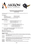
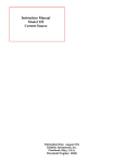
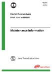
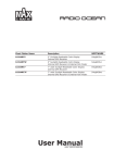
STYLE 9313 CONTROLLER
INSTALLATION & OPERATING INSTRUCTIONS
The Style 9313 Controller from Akron is designed to provide reliable and accurate valve control with valve position
indication through 10 LED (Light Emitting Diodes) indicators identifying the degree of Open/Close.
Features of the Akron Style 9313 Controller include:
Protected against EMI (Electro Magnetic Interference), both incoming and outgoing
Programmable Auto Open (not preset)
Works with both 12 and 24 Volt systems
Retrofits to existing apparatus
4 ¼” square face
Meets all aspects of NFPA 1901
Carries Akron’s 5 year warranty against manufacturing defects
Standard Components
Controller
Wiring Harness for connection to the valve-10’ length standard
Note: the Controller is designed for use only with Akron Brass Electric Valves. Do not use with any other manufacture of
valve. Doing so will void any warranty.
INSTALLATION INSTRUCTIONS
Select the mounting location for the Controller. The Controller can be mounted from the outside with (4) Screws and
Delrin Nuts (included). Torque requirement is 6-8 lb-in for the nuts. The unit requires 2 ½” clearance behind the panel.
Dimensions for a panel cutout are shown in figure #1.
Warning: The Controller is a sealed unit. Disassembly of the unit will void any warranty. There are no user serviceable
parts in the Controller. If service is required the unit should be returned to the factory. Also, do not cut any connections.
Doing so will void any warranty and prevent product returns.
Note: The Valve and Auxiliary wires are plugged prior to shipment. These plugs must be removed before connections can
be made. If a lead is not being utilized, the plug should be left in place to prevent moisture damage.
CONTROLLER LEADS
Each Controller has three (3) Connectors extending from the back of the unit.
Power Connection lead
The Controller Power connection utilizes a 2 prong Weather-Pack connector. A mating Weather-Pack connector is required (customer supplied-see appendix for purchasing information). Proper wire gauge is required to assure a quality
connection. 12 gauge wire is recommended. Heavier gauge wire is required for runs over 10’.
Note: when using larger than 12 gauge wire, be sure to use a 12 gauge connector and splice after the connector so as to
not void any warranty. The splice should be made close to the Controller.
121568
For best connections all grounds should be made to either the frame or to a similar solid surface. A faulty ground will
lead to unit malfunction.
Added loads on any power wire should be avoided.
Direct runs are recommended for all connections.
12 Volt systems require a minimum of 11.5 volts at the valve under full load (28 amps).
24 Volt systems require a minimum of 22 volts at the valve under full load (14 amps).
Typical current draw for a 2”-3” valve is 2-4 amps in a 12 volt system (1-2 amps for 24 volt). It will be slightly higher for
larger sized valves. When the mechanical stops are reached (full open or full closed) current draw can reach 28 amps in a
12 Volt system and 14 Amps in a 24 Volt system.
Note: The truck should always be running before operating the Controller.
Electric Valve Connection lead
Use an Akron Wiring Harness to connect the Controller to the Valve Motor. The standard length is 10’. All Wiring
Harnesses have Deutsch connectors. See the appendix for a complete list of Wiring Harnesses.
Auxiliary Connection lead
The Controller Auxiliary connection is a 3 prong Weather-Pack connector.
To connect a Master to an Auxiliary, an Auxiliary Cable is required. Standard length is 10’. See the appendix for a list of
Auxiliary Cables.
NOTE: When utilizing an Auxiliary, a separate power lead is required for the Auxiliary
AUTO OPEN FEATURE
Auto Open allows a pump operator to open a fully closed valve by momentarily pressing the “OPEN” button.
The Auto Open feature is factory set in the DISABLED position. The Auto Open option can be changed to on or off in the
Setup Mode.
If Auto Open is disabled, the valve only operates as long as an “OPEN”, or a “CLOSE” button is being pressed.
INITIAL SETUP
The Controller must be calibrated when used for the first time with a new valve or with a different valve. When used for
the first time, the LED Bar Graph Display will flash indicating calibration is needed.
Calibration can be done easily by accessing the Setup Mode shown below.
Note: When a Controller is used as an Auxiliary, the Setup Mode is not accessible. Calibration and setup are only
necessary for a Master Controller.
SETUP MODE
Press and hold both the “OPEN” and “CLOSE” buttons for 15 seconds. The display will flash once. The
Controller is now in the SETUP MODE. Both buttons can be released.
The middle YELLOW LED should be the only LED illuminated.
The “OPEN” button can be used to move through the setup options.
The “CLOSE” button will activate a selected function.
FUNCTIONS when the LED is lighted
Valve Calibration
Middle Yellow LED
Auto Open Feature
Green LED
Exit Setup Mode
Red LED
VALVE CALIBRATION
With the middle Yellow LED lighted, press the “CLOSE” button. The valve will cycle to fully closed, fully open, and back to the fully closed position.
The Valve is now calibrated to the Controller and ready for operation.
TO EXIT CALIBRATION MODE
Press and release open button, if the green LED is blinking, Auto open is disabled. If the green LED is not
blinking, Auto open is enabled. If you wish to change the auto open setting use the close button to change
option. Press & release the green button again until only the red LED is lighted. Press the close button. All
LED’s will flash once before the controller returns to normal operation.
AUTO OPEN Option
While in the SETUP MODE, press and hold the “OPEN” button until the GREEN LED is lighted.
If the green LED is BLINKING, Auto Open is DISABLED
If the green LED is SOLID, Auto Open is ENABLED
Use the “CLOSE” button to change the setting.
CONTROLLER INSTALLATION DIAGRAM
SPECIFICATIONS:
Electrical Inputs:
Power 9-32VDC@300mAmax (no load)
Valve Control 12 or 24VoltsDC
CommunicationModbus Serial Connection
Environmental
Temperature
-40C to +80C (Operating)
-40C to +85C (Storage)
Minimum Operations Voltage – 11.5 VoltsDC
Maximum Operations Voltage – 32 VoltsDC
Display Type – LED
TROUBLESHOOTING
Problem
Cause
Solution
Red or Green LED’s do
not illuminate but the
Valve will open and close.
Too much voltage drop or not
enough current for the unit to
sense the end of travel.
1. Truck engine must be running
2. Check the voltage to the Controller.
12 Volt systems require 11.5 volts @ 28 amps.
24 Volt systems require 22 volts @ 14 amps.
3. Check all wiring from the power source to the
Controller. A minimum of 12 gauge wire should
be used. For lengths over 10’ heavier gauge wire is
required.
4. Check all connections and grounds for loose
connections.
Red and Green LED’s
illuminate prematurely
before the Valve is fully
open or closed.
1. Short in the Motor or Controller 1. Remove the Motor from the Gear Housing and
2. Gear system is jammed.
measure the amps needed to operate the Motor. The
3. Seat or Valve Ball is damaged Motor should require approximately 1.5 amps on 12
Volt systems; .75 amps for 24 volt systems.
2. Operate the Manual Override on the Actuator. If
difficulty is found, check under the housing cover for damaged parts causing the Valve not to operate
properly.
3. Check the Valve waterway for any obstruction or
damage to the Ball or Seats.
The yellow LED
illuminates but the Valve
does not move while the
Motor continues to run.
Worm Gear is disengaged
Remove the Gear Housing Cover and check for
damaged parts. Check the Groove Pin in the Worm
Gear for proper engagement.
Valve Actuator moves at
the end of the open or
closed function.
Loose screws
While some motion is normal from torque, excessive
movement may be caused by loosened screws.
Before tightening the screws, remove them and apply
Permabond LM 113 or Loctite 222 and retighten.
No Power to the
Controller
Bad wiring
Open breaker or blown fuse
Power not connected.
Check all power connections, wires, fuses or breakers.
Be sure a separate power wire is connected to any
Controller used as an Auxiliary.
Valve Actuator does not
work. Motor does not
drive.
1. No signal from the Controller
to the Actuator Motor.
2. Defective Actuator Motor
3. Worm Gear system jammed.
4. Planet Gear system jammed.
1. Check all connectors are fully engaged.
Check the voltage through the Wiring Harness
should be at least 11.5 volts for 12 volt systems and
22 volts for 24 volt systems. Check the signal from
the Controller.
2. Remove the Motor from the Actuator and operate
the Motor to be sure the Motor Shaft turns freely.
3. Check the Worm Gear. Operate the Valve using the
Manual Override.
4. Remove the Motor and check the Planet Gears.
Motor Runs but Valve
does not operate
1. Grove Pin is missing from the
Shaft.
2. Gear Sector is not engaging
the Worm Gear.
3. Motor Shaft is disengaged
from the Planet gears.
1. Check the Groove Pin is fully engaging the Worm
Gear and Shaft.
2. Check if the Worm Gear and Sector Gear are
engaged.
3. Remove the Motor and check for engagement of the
Motor Shaft and Planet Gears.
Valve closes when the
OPEN Button is pressed
and vice versa.
1. Sector Gear is in the wrong
position.
2. Cable wiring is reversed.
1. Reposition the Sector Gear.
2. Replace the Cable.
Valve OPEN/CLOSE
LED’s switch immediately
from Red to Green and
vice versa.
1. Wiring
2. Mechanical Binding
1. Check wiring as explained in Problem #1.
2. Remove the Motor and check the Shaft turns freely.
Also, operate the Valve manually via the Override to
check for binding.
APPENDIX
Mating Weather-Pack Connectors for Power Cable
A Mating Weather-Pack connector must be used to connect to the power source.
DO NOT CUT THE CONNECTOR on the power wire of the controller.
Doing so will void the warranty.
Part number 9300-0058 is a packet of (5) mating Weather-Pack connections.
Wiring Harnesses
Part Number
7-21-290
7-21-381
9303-0016
9303-0012
9303-0013
9303-0014
Description
10’ long (standard length)
15’ long
20’ long
30’ long (utilizes Potting Shells and 10 gauge wire)
38’ long (utilizes Potting Shells and 10 gauge wire)
50’ long (utilizes Potting Shells and 8 gauge wire)
Auxiliary Cables
Part Number
9300-0052
9300-0055
9300-0056
Description
10’ long (standard length)
25’ long
50’ long
Style 9313 Controller Ordering Information
Part Number
Description
9313-0001
Controller Only
9313-0002
Controller w/ 10’ Wiring Harness
9313-0003
Controller w/ 10’ Auxiliary Cable
PHONE: 330.264.5678 or 800.228.1161 I FAX: 330.264.2944 or 800.531.7335 I www.akronbrass.com
revised: 4/09
WARRANTY AND DISCLAIMER: We warrant Akron Brass products for a period of five (5) years after purchase against defects in materials or workmanship. Akron Brass will repair or replace
product which fails to satisfy this warranty. Repair or replacement shall be at the discretion of Akron Brass. Products must be promptly returned to Akron Brass for warranty service.
ISO 9001 REGISTERED COMPANY
We will not be responsible for: wear and tear; any improper installation, use, maintenance or storage; negligence of the owner or user; repair or modification after delivery; damage; failure to
follow our instructions or recommendations; or anything else beyond our control. WE MAKE NO WARRANTIES, EXPRESS OR IMPLIED, OTHER THAN THOSE INCLUDED IN THIS WARRANTY
STATEMENT, AND WE DISCLAIM ANY IMPLIED WARRANTY OF MERCHANTABILITY OR FITNESS FOR ANY PARTICULAR PURPOSE. Further, we will not be responsible for any consequential,
incidental or indirect damages (including, but not limited to, any loss of profits) from any cause whatsoever. No person has authority to change this warranty.
© Premier Farnell Corporation. 2000 All rights reserved. No portion of this can be
reproduced without the express written consent of Premier Farnell Corporation.