1
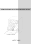
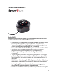
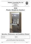
Catalog No. 877-92
Operating Instructions
SKC Inc.
863 Valley View Road
Eighty Four, PA 15330 USA
Tel: 724-941-9701
e-mail: [email protected]
Form #40085—Rev 0401
1
Table of Contents
Introduction .................................................................................... 1
DataTrac Setup ............................................................................. 2
SKC DataTrac Pump Manager ..................................................... 4
SKC Real-time Monitor .................................................................. 5
STEL/Timed Run ..........................................................................13
SKC Pump Scheduler...................................................................14
Example Scheduler Program........................................................25
SKC Pump History........................................................................29
Archive History .............................................................................32
Reports .........................................................................................32
Index .............................................................................................38
Indicates a premier feature of DataTrac software.
Indicates a reminder.
Indicates a warning.
1
Introduction
Introduction
DataTrac Software for Leland Legacy
Features
• Program a sampling operation from a PC
• Calibrate pump flow to a primary standard
• Display the operating state including flow rate, temperature, atmospheric
pressure, run-time, and battery status of the connected pump
• Create and save a sampling program without a pump connected to the PC
• Program a sampling operation of up to ten sampling sequences, each
capable of different flow rates
• Download pump run time data and history to your PC
• Document sampling history using the sample setup feature
• Print a history file containing pump run time data
• Print a worker exposure profile containing run time data and pump history
• Document date of pump calibration
DataTrac System Requirements
•
•
•
•
Any IBM-compatible PC with a 80486 processor or higher
SVGA display system or better
CD-ROM drive
An available serial port (i.e., a port not used by a mouse, modem, personal
digital assistant (PDA), or other device)
• A mouse
• Microsoft® Windows® 98 or higher
DataTrac Components
•
•
•
•
•
DataTrac CD-ROM
Interface box
9-pin (male to female) serial cable
9-pin male to 25-pin female serial adapter
Operating instructions on CD
1
DataTrac Setup
DataTrac Setup
Installing DataTrac Software
1.
Close all applications
2.
Put the DataTrac CD in the drive. It should autorun the CD when you close
the drive. If it does not autorun the CD, then go to:
- Start
- Run
- Browse for setup.exe on the CD drive
Note: If an existing version of DataTrac is already installed you may be required to
remove that version before you can install the new one. If this is the case, follow the
instructions in the Install Shield to remove DataTrac. Then resume from Step 1 to
install.
3.
Connect the DataTrac adapter to your PC serial port. The serial port is usually
a 9-pin male connector. If it is a 25-pin male connector, use the 25-pin female
adapter included in the DataTrac package. Connect the other end of the adapter
cable to the pump’s interface port (Figure 1).
Interface cable
DataTrac
adapter
Pump
interface port
OW
FL
L / mins
alternative 9-pin male to 25-pin
female adapter
Figure 1. Hardware Setup
DataTrac has limited use without an active pump connected to the PC, however, a
program can be set up and saved to a PC without a pump connected to the PC.
4.
Activate the pump LCD by pressing any of the three buttons on the pump
keypad.
2
DataTrac Setup
5.
Launch DataTrac by double-clicking on the DataTrac icon. The
program will display the QuickComm window (Figure 2).
6.
Select a communication port. Port selection will depend upon your
computer type; most computers use Port 1 or 2. Click on the Open Port Button.
An incorrect selection displays an error message. A correct selection will display
a shaking-hands icon in the QuickComm window (Figure 2A).
Figure 2. QuickComm Window
Figure 2A. Successful
Communication
DataTrac will “remember” the communication port the first time the program
is launched and will automatically select the proper port during subsequent
launches.
7.
If the date and time settings
on the PC and pump differ by
more than 5 minutes, a Time
Discrepancy Alert window
will display (Figure 2B).
Reconcile the date and time
and click OK.
8.
DataTrac will load and
display the SKC DataTrac
Pump Manager window (see
Figure 3, p. 4).
Figure 2B. Time Discrepancy Alert Window
Recommended for first time users: Connect a Leland Legacy pump to your PC
and explore the features of DataTrac through the Real-time Monitor (p. 6).
3
SKC DataTrac Pump Manager
SKC DataTrac Pump Manager
The SKC DataTrac Pump Manager window (Figure 3) is the first window that opens
in DataTrac. All windows are accessible from this main window.
Figure 3. SKC DataTrac Pump Manager Window
SKC DataTrac Pump Manager Menus
File Menu
Exit.................................exits the program and returns to Windows
View Menu
Pump Scheduler......... .opens the SKC Pump Scheduler window
STEL/Timed Run .........opens the STEL/Timed Run window
Sample Sheet ................opens the Sample Sheet Setup window
Report ...........................loads a report file previously saved to a PC
Pump History ..............opens the SKC Pump History window
Archive History ...........loads a history file previously saved to a PC
Calibration Info ...........opens Calibration Info window
Real-time Monitor .......opens the SKC Real-time Monitor window
Tools Menu
Set Date/Time...............opens the Set Date/Time for Pump window
Temperature and Pressure
Calibration....................opens Temperature and Barometric Calibration
Help Menu
About ............................displays the PC and pump software version
numbers, pump serial number, date of last full
calibration, language, and information about
downloading the latest version of DataTrac.
Online Manual .............displays DataTrac Software Operating Instructions (Form #40085) in PDF format
4
SKC Real-time Monitor
SKC Real-time Monitor
The SKC Real-time Monitor window (Figure 4) directly controls the pump, allows
calibration of flow rate, displays a real-time readout of pump operations, and displays the connected pump‘s serial number.
B
C
D
A
F
E
G
Figure 4. Real-time Monitor Window
A.
B.
C.
D.
E.
F.
G.
Real-time Monitor Display (p. 6)
Flow Calibrate Buttons (p. 7)
Temperature Display (p. 9)
Pressure Display (p. 10)
Pump Controls Buttons (p. 10)
Units Selection Buttons (p. 11)
Fault Options (p. 11)
Real-time Monitor Menus
File Menu
Exit.................................returns to the previous screen
Tools Menu
Clear Schedule .............clears the programmed pump schedule from
the pump
Clear STEL/
Timed Run....................clears programmed timed run from the
pump
Clear History................clears the pump history
5
SKC Real-time Monitor
Real-time Monitor Display
The Real-time Monitor display (Figure 5) shows the operating status of the connected
pump.
Figure 5. Real-time
Monitor Display
Pump Status
Cell Readout
Run:
Hold:
Fault (Run):
Fault (Hold):
Prog (Hold):
Prog (Run):
Prog (Sleep):
Reset:
Sleep:
User setup:
Pre-Cal Flow:
Post-Cal Flow:
Operating State of the Pump
pump in run mode
pump in hold mode
pump in flow fault status while running
pump in flow fault status and hold mode
pump in hold mode while running a
program
pump in flow mode while running a
program
pump in sleep mode while running a
program
run time data has been zeroed
pump in sleep mode
pump user interface accessed and user
adjusting pump
single-point calibration mode; first
calibration average, date, and time
single-point calibration mode; final
calibration average, date, and time
6
SKC Real-time Monitor
Timed Run:
Low Bat:
Flow adjust:
pump running a preset sampling time (ST)
battery depleted
pump flow rate or flow correction being
adjusted by user
Flow Cell .............current pump flow rate in L/min
Volume Cell ........total volume of air pumped since reset
Run time Cell .......total run time of pump since reset
Total Time Cell ....total run time of pump since factory calibration
Battery Cell ...........graphically displays battery life. The battery life is indicated
by a colored bar with low (-) charge indicated on the left side
and full (+) charge indicated on the right side. A long colored
bar (closer to the + end) represents a battery near a full charge.
A short colored bar (closer to the - end) represents a battery
near depletion.
Data in the Real-time Monitor display cells is updated every 5 seconds.
Flow Calibrate Buttons
The Flow Calibrate buttons (Figure 6) are used to
apply a correction to the pump flow rate during
calibration to a primary standard
Controls
Function
S ...............................increases correction of pump
flow rate
Figure 6. Flow Calibrate
T ...............................decreases correction of
pump flow rate
Reset .........................zeroes the value in the Approx. Correction cell
Comm Checking ....turns the communication checking function on or off. This
feature allows the user to unplug a pump and plug in
another pump without causing a communication error.
Adjusting the Approximate Flow Correction
The Leland Legacy pump should be calibrated before each sample run.
1.
Click the Reset button to reset the correction value to 0.00 L/min.
Changing the pump flow setting will also reset the correction value to
0.00 L/min.
7
SKC Real-time Monitor
2.
Turn on the pump and connect the inlet port of the pump to primary
standard calibrator. Read the flow displayed on the calibrator.
3.
Click on the S or T buttons in the Flow Calibrate window until the
calibrator displays the desired flow rate.
When adjusting the correction, the flow rate displayed on the calibrator
changes, the flow rate displayed on the pump does not change. The range of
flow correction is ± 2.5 L/min.
4.
Repeat calibration after sampling to verify flow.
Example: The desired flow rate is 10 L/min.
Set the pump to 10 L/min. If the calibrator displays 9.7 L/min, click the S button
in Flow Calibrate until the calibrator displays 10 L/min. If the calibrator displays
10.5 L/min, click the T button in Flow Calibrate until the calibrator displays 10 L/
min. Repeat calibration after sampling to verify flow.
Comm Checking Buttons
The Comm Checking buttons (Figure 7) turn the communication checking function
on or off. Comm Checking monitors the interface cable connection between the PC
and the pump. The default value is On. If the interface cable becomes detached,
an error message displays (Figure 8). Reconnect the pump and click on Retry. If
Comm Checking is in the “off ” position, the pump’s real-time information will not
be updated.
If programming more than one pump, turn Comm Checking off by clicking the
Off Button. Turning Comm Checking off when programming multiple pumps will
eliminate the error message that displays each time the pump is disconnected.
Figure 7.
Comm Checking Button
Figure 8.
Error Message
When Comm Checking is turned off, the pump will enter Sleep mode five minutes
after the last interaction between the computer and the pump.
8
SKC Real-time Monitor
Temperature Display
The Temperature Display (Figure 9) shows the temperature of the air entering the
connected pump.
Cell
Readout
Min .......................................................minimum air temperature during the
program run
Max .......................................................maximum air temperature during the
program run
TWA .....................................................Time-Weighted Average (TWA) of all air
temperatures
Ambient ..............................................current air temperature Note: The Temperature
Display is not ambient air temperature. It
reflects the temperature of the air within the
pump.
Figure 9. Temperature Display
The Min, Max, and TWA are calculated from the
temperatures measured during the total run time
of the pump. Unless reset, the temperature data
will remain in memory and will be included in
future Min, Max, and TWA calculations. Reset
by clicking on the Reset Volume, Temp, Run
Time, and Pressure button in the Pump Controls
section of the Real-time Monitor (Figure 9A).
Figure 9A. Reset Volume,
Temp, Run Time, and
Pressure Button
9
SKC Real-time Monitor
Pressure Display
The Pressure Display (Figure 10) shows the atmospheric pressure of the air entering the connected pump.
Cell
Readout
Min .......................................................minimum atmospheric pressure during the
program run
Max .......................................................maximum atmospheric pressure during the
program run
TWA .....................................................Time-Weighted Average of all atmospheric
pressure
Ambient ..............................................current atmospheric pressure
Figure 10. Pressure Display
The Min, Max, and TWA are calculated from
the atmospheric pressure measured during the
total run time of the pump. Unless reset, the
pressure data will remain in memory and will
be included in future Min, Max, and TWA
calculations. Reset by clicking on the Reset
Volume, Temp, Run Time, and Pressure button
in the Pump Controls section of the Real-Time
Monitor (Figure 9A).
Figure 9A. Reset Volume,
Temp, Run Time, and
Pressure Button
Pump Controls Buttons
The Pump Controls buttons (Figure 11) directly control the connected pump.
Control
Function
Run ...........................................places the pump in RUN
Hold .........................................places the pump in HOLD
Set Flow ...................................opens the Monitor Set
Flow window (similar to
Figure 23, p. 18)
Figure 11. Pump
Controls Buttons
Reset Volume,
Temp, Run Time,
and Pressure ...........................clears the accumulated data: volume, temperature
(Min, Max, and TWA), time, and pressure (Min,
Max, and TWA)
10
SKC Real-tIme Monitor
Units Selection Buttons
The Units Selection buttons (Figure 12) allow the user to select the temperature and
pressure units of the connected pump.
Control
Function
Fahrenheit ...................................selects the Fahrenheit temperature scale
Celsius .........................................selects the Celsius temperature scale
in-Hg ............................................selects the atmospheric pressure display in units of
inches of mercury
millibar ........................................selects the the atmospheric pressure display in units
of millibar
mm-Hg .........................................selects the the atmospheric pressure display in units
of millimeters of mercury
Fault Options
Figure 12. Units Selection Buttons
Figure 13. Fault Options
The Fault Options (Figure 13) allows the user to select the time the pump spends in
flow fault mode and the number of times the pump attempts to restart.
Cell/Control
Time to Fault (sec)
Readout/Function
Click on the box and enter a number from 5 to 30.
This value is the number of seconds the pump
spends in Flow mode before going into Flow Fault
Hold mode.
Number of Retries
Click on the box and enter a number from 0 to 25.
This value is the number of times the pump attempts
to restart once it goes into Flow Fault Hold mode.
11
SKC Real-tIme Monitor
Time to Retry (sec) ....................click on box and enter a number from 5 to 600. This
value is the number of seconds between when the
pump goes into Hold after a flow fault and when
it restarts.
Set Fault Options .......................saves the chosen options
Fault On/Fault Off .....................enables/disables Fault mode. When set to “off,” no
flow fault will occur.
12
STEL/Timed Run
STEL/Timed Run
The STEL/Timed Run window (Figure 14) allows the user to set a pump run for a
predetermined length of time, eg., 15 minutes. Once the STEL/Timed Run is set,
the user presses the ST keys on the pump simultaneously to start the run. After
the timed run is completed, the pump will stop automatically.
Figure 14. STEL/Timed Run Window
STEL/Timed Run Menus
File Menu
Exit.............................exits the STEL/Timed Run window
Tools Menu
Clear STEL
in Pump ....................cancels the programmed sampling time
Change Default
Flow Buttons ............displays a text box reminder on how to change the
default flow rates displayed on the Flow Selection
buttons in the STEL/Timed Run window
STEL/Timed Run Buttons
Control
Function
Flow Selection (L/min) .............permits selection of pump flow rate
Run Time ....................................permits pump run time to be set in hours and minutes
To Pump ......................................sends settings to pump
Reset Volume, Run
Time, Temps, Pressures ............resets min, max, and TWA values in Real-time
Monitor
To program a sampling time, use the flow selection buttons and scroll bar to select a
flow rate. Enter the duration of the sample run by clicking on the run time box and
entering the run time. The sampling time can be set up to 99999 minutes.
Once the flow rate and sampling time have been set, click the To Pump button to
program the connected pump.
13
SKC Pump Scheduler
SKC Pump Scheduler
The SKC Pump Scheduler window (Figure 15) is the DataTrac programming window.
Programs can be created, sent to a pump, saved to a PC, loaded from a disk or a
pump, and printed.
B
G
H
A
F
C
I
D
E
Figure 15. Pump Scheduler Window
A.
B.
C.
D.
E.
F.
G.
H.
I.
Program Edit Bar (p. 15)
Pump Schedule (p. 16)
Programming Buttons (pp. 16-17)
Set Flow Button (p. 18)
Calendar (p. 19)
Clock (p. 19)
Time Bump All Dates Buttons (p. 20)
Repeat Scheduler (p. 24)
Digital Time Display (p. 20)
14
SKC Pump Scheduler
Pump Scheduler Menus
File Menu
Open ......................opens a pump program previously stored on disk
Save .......................saves a pump program to a PC
Print ........................ prints the pump program schedule displayed on the
screen
Exit.........................exits the Pump Scheduler window
View Menu
Cycle Scheduler ...........opens Cycle Scheduler window.
Preview Repeat
Scheduler ......................opens Repeat Scheduler window
Scheduler Presets ........opens Scheduler Options window
Clock Resolution .........sets the clock resolution
Tools Menu
Clear Schedule .............clears the programmed pump schedule
Clear History................clears the pump history
Compare Pump Clock/
PC Clock .....................opens the time display window and allows the
pump and PC times to be synchronized (see
Figure
2B on p. 3)
Comm Checking ..........Enables/disables communication checking.
Indicated by 3 on menu.
Program Edit Bar
Figure 16. Program Edit Bar
The Program Edit Bar (Figure 16) is where the user sets up a pump program. A
program is set up by entering the Flow Rate, Start Date/Time, Stop Date/Time, and
Duration to the cells of the Program Edit Bar.
A pump program contains these sampling parameters:
Parameter
Rate
Value
flow rate in L/min
Start Date
start date of the program
Start Time
start time of the program
Stop Date
stop date of the program
Stop Time
stop time of the program
Duration
total run time of the program in days: hours:
minutes: seconds
To program the above parameters into the cells of the Program Edit Bar, click on
the Programming buttons (p. 16) that select the value of the parameters, then click
on the appropriate cell.
15
SKC Pump Scheduler
Pump Schedule
The Pump Schedule (Figure 17) contains pump programs (or Pump Schedules) set
by the Program Edit Bar. The pump is programmed for a sampling operation by
sending this list of programs to the pump‘s memory. The Pump Schedule is built
by using the Programming buttons described in the next section.
Figure 17. Pump Schedule Containing Programs
Before entering a program into the Pump Schedule, go to the Scheduler Options
window (Figure 33, p. 22) to reset data and pump history.
Programming Buttons
The Programming buttons (Figure 18) select the program parameters, insert
programs into the Pump Schedule, write programs to the pump, and read programs
from the pump.
Figure 18. Programming Buttons
Button
Function
Clr ..........................erases the program in the Program Edit Bar
+Day ......................adds one day to the program in the Program Edit Bar, which is useful
for programming same start and stop times on consecutive days
or use Repeat Scheduler (see p. 24).
Insert .....................places the program displayed in the Program Edit Bar into the
Pump Schedule
Cut .........................clears the selected (highlighted) program in the Pump Schedule
and places it into the Program Edit Bar where it can be edited
FromPump ...........reads the program stored in the pump and displays it in the Pump
Schedule
ToPump ................writes the program displayed in the Pump Schedule to the
pump
16
SKC Pump Scheduler
Insert Button
To insert the completed program from the Program Edit Bar into the Pump Schedule
(Figure 17, p. 16), click on the Insert button (Figure 18). The Pump Schedule can
hold over 50 programs. However, if a large number of programs are to be stored,
consider using the Cycle Scheduler (see p. 23) or the Repeat Scheduler (see p. 24).
Cut Button
To clear the selected (highlighted) program from the Pump Schedule and place it
into the Program Edit Bar, click on the Cut Button (Figure 18, p. 16). A program can
also be cut by double-clicking the program number or the line number to the left
of the rate column of the Pump Schedule (Figure 17, p. 16).
Clear the history either in the Scheduler Presets menu or in the Tools menu and
set Scheduler Presets in the View menu before sending a program to the pump by
clicking the ToPump Button.
ToPump Button
To write the Pump Schedule to the pump, click the ToPump button (Figure 18,
p. 16). A dialog box will appear (Figure 19).
Click OK in the dialog box to send the program to the
pump. A “Program Loaded” dialog box (Figure 20)
will appear on screen to verify the operation.
An overwrite dialog box will appear if a program
has already been sent to the pump. Click Yes if you
wish to overwrite the program in the pump.
Writing a program to the pump will cause the PROG
icon to appear on the pump LCD (Figure 21), which
will remain active until all programs have run.
The pump cannot be controlled manually until all
programmed schedules have run.
Figure 19. Confirmation
Dialog Box
Figure 20. Program Loaded
Dialog Box
Edit a Program
To edit a program displayed in the Pump Schedule,
double-click on it. This will remove it from the Pump
Schedule and place it in the Program Edit Bar. Any
program already in the Program Edit Bar will be erased.
Click insert once the program is edited to move it back
to the Pump Schedule.
17
Figure 21. Leland Legacy
with Program
SKC Pump Scheduler
FromPump Button
To display a Pump Schedule from a previously programmed pump, click on the
FromPump button (Figure 18, p. 16).
Time Bump Buttons
To increase or decrease all program start and stop times in the Pump Schedule, click
on the Time Bump buttons (Figure 30, p. 20).
Save a Program (File Menu)
To save information from the Pump Schedule to a PC as a program file, select the
Save command from the File menu.
The default extension “.pgm” is used to indicate Pump Schedule files.
Open Program (File Menu)
To open a previously stored program, select Open from the File menu.
Print Program (File Menu)
To print the Pump Schedule information displayed on the screen, select Print from
the File menu.
Set Flow Button
The Set Flow button (Figure 22) opens the Scheduler Set Flow
window (Figure 23) to allow the user to set the pump flow
rate.
Scheduler Set Flow Window
The Scheduler Set Flow window (Figure 23) allows the user to
select the pump flow rate using the numbered flow buttons and
the scroll bar.
Figure 22.
Set Flow
Button
Select Flow Rate
To set the flow rate, click on the desired flow
rate button. The new flow rate appears in the
display cell.
Scroll Bar
To increase or decrease the displayed rate, use
the scroll bar.
Enter Flow Rate
To enter the displayed flow rate into the Rate cell
of the Program Edit Bar, click on OK.
Previous Button
To reset the displayed flow rate to the previously
set pump flow rate, click on the Previous button
in the Scheduler Set Flow window.
18
Figure 23.
Scheduler Set Flow Window
SKC Pump Scheduler
Calendar
The Calendar (Figure 24) shows the time interval
over which the pump can be programmed. Use the
Calendar to select the start and stop dates for the
scheduled sample run.
Selecting a Date
To select a date, click on it then click on the Start
Date/Time or Stop Date/Time cell in the Program
Edit Bar to enter the date into that cell. Use the right
and left arrows to select a different month.
Figure 24. Calendar
Clock
The Clock (Figure 25) consists of a clock face, a digital
display corresponding to the time on the clock face, AM
and PM Buttons, and the current date and time. The clock
face perimeter is divided into 10-, 15-, and 30-minute and
1- hour intervals depending on the selected clock resolution
(Figure 26).
Figure 25. Clock
Clock Resolution
To change the Clock Resolution or time
intervals to 10, 15, or 30 minutes or 1 hour,
select the Clock Resolution command from
the View menu (Figure 26). Clock Resolution
can also be selected by clicking on the clock
face perimeter between the digits.
Figure 26. Clock Resolution
Selecting Time Using the Clock Face
To select the start or stop times, select the
clock resolution (Figure 26), click on the clock face
perimeter, the AM or PM button, and then click on
the Start Date/Time or Stop Date/Time cell of the
Program Edit Bar.
Example: To set the time to 4:15 PM, select “15
minutes” from the Clock Resolution menu (Figure 26),
click on the clock perimeter at 4:15 (Figure 27), and click
on the PM button.
19
Click here
Figure 27.
Select 4:15
SKC Pump Scheduler
Selecting a Time Using the Digital Time Display
The Digital Time display (Figure 28) can also be used to select the
time, especially outside the clock resolution settings. Double-click on
the time display to highlight it (Figure 29), then key in the desired
time (including the colon). One or more numbers can
be individually selected by clicking and dragging
across the digit to be changed. Click on the appropriate
time cell in the Program Edit Bar to enter the time
into that cell.
Figure 28.
Digital Time
Display
Figure 29.
Select Time
Display
Time Bump all Dates Buttons
The Time Bump all Dates buttons (Figure 30) add or subtract the
selected time interval to all program Start Time and Stop Time in
the Pump Schedule.
Time Interval
Click on the desired time interval.
Minus (-) Button
To subtract the selected time interval from all
programming steps, click on the - button.
Plus (+) Button
To add the selected time interval to all programming
steps, click on the + button.
20
Figure 30.
Time Bump All
Dates Buttons
SKC Pump Scheduler
Date/Time Display
To access the Date/Time Display window (Figure 31), go to the Tools menu and
select Compare Pump Clock/PC Clock. This feature allows the time and date of the
PC and the connected pump to be synchronized.
Figure 31. Date/Time Display Window
Resetting the pump time will issue a Clear History Message (Figure 32). The
pump history must be cleared before the pump time can be reset.
Figure 32. Clear History Message
21
SKC Pump Scheduler
Scheduler Options
To access the Scheduler Options window (Figure 33) in the SKC Pump Scheduler,
go to the View menu and select Scheduler Presets. The Scheduler Options window
includes User Lock Out, Clear History, and Reset Volume, Time, Temperatures, and
Pressures. The Scheduler Options take effect when the Pump Schedule is sent to the
pump’s memory from the SKC Pump Scheduler window (see p. 14).
Figure 33. Scheduler Options
Button
Function
User Lock Out ......................Click on the box to activate (a checkmark will appear)
or click again to remove checkmark and deactivate; User
Lock Out will prevent anyone from altering the pump
operating parameters once a schedule has been sent to
the pump. However, the operator will still be able to
scroll through the data display. Select “Unlock Pump
After Schedule has Completed” for automatic deactivation or choose “Keep Pump Locked...” for continued
security (unlock in DataTrac).
Reset Volume, Time,
Temps, Pressures .................Click on Yes to activate or No to deactivate; Yes will
reset the accumulated volume pumped, time dura-tion,
minimum and maximum temperatures, and pres-sure
data to zero (0).
Clear History........................Click on Yes to activate or No to deactivate
To set the values and return to the previous window, click the OK Button.
All activated options will take effect when the ToPump button (Figure 18, p. 16) is
clicked. The ToPump button sends the information in the Pump Schedule (Figure
17, p. 16) to the connected pump.
22
SKC Pump Scheduler
Cycle Scheduler
To access the Cycle Scheduler window (Figure 34) in the Pump Scheduler, go to
the View menu and select Cycle Scheduler. The Cycle Scheduler window allows
the user to program intermittent (repeated start/stop) sampling cycles that will
run over several days in a minimal number of steps. See pp. 25 to 28 for an example
schedule.
Figure 34. Cycle Scheduler
Cell/Button
Readout/Function
Cycle Setup Run cell ........enter time that each cycle is to run
Cycle Setup Hold cell .......enter time between each cycle
Seconds, Minutes,
Hours buttons ....................select time increment for Run and Hold
Flow Rate cell .....................enter pump flow rate in L/min
Start Date, Time cell .........enter starting date and time of first cycle
Number of Cycles cell ......enter total number of cycles to run
Cycle-Scheduler
Times ...................................DataTrac automatically compiles the cycle schedule
based on the user input and summarizes it in this cell.
Total Run Time and Total Volume are also calculated
and displayed
Duty-Cycle Visualizer ......bar graph indicates how much of the time the pump
will be running
Send Schedule to
Pump button .......................sends the cycle program to the attached pump
23
SKC Pump Scheduler
Repeat Scheduler
To activate the Repeat Scheduler (Figure 35), go to the Repeat Schedule cell in
the Pump Scheduler window and click in the box until a check mark appears.
Click on the desired time frame (daily or weekly) and enter the desired number
of cycles in the Execute Count cell. Enter the desired flow rate in the Set Flow
cell or click the Set Flow button. Click the ToPump button. Go to the View menu
and select Preview Repeat Scheduler. A summary including total run time and
volume will appear. The Repeat Scheduler allows the user to repeat a pump
schedule over many weeks. The schedule can vary from day-to-day. See pp. 25 to
28 for an example schedule.
There must be a Pump Schedule in place to take advantage of this feature.
Figure 35. Repeat Scheduler
Cell/Button
Readout/Function
Repeat Schedule cell ...........click to activate the Repeat Schedule (checkmark)
Daily/Weekly buttons .........click desired repeat interval
Execute Count cell ...............enter number of intervals schedule is to repeat
Set Flow cell and button ....enter or select pump flow rate in L/min
24
Example Scheduler Program
Example Scheduler Program
This example program demonstrates step-by-step how to use the SKC Pump Scheduler window (p. 14) to set a program.
A sampling operation requires the Leland Legacy to sample at a constant flow of
10 L/min from 8:00 AM to 4:00 PM daily for one work week. Enter the parameters
as follows.
To Reset Volume, Time, Temperature, and Pump History
To set the flow rate:
Click on the Set Flow button. The Scheduler Set
Flow window opens. Click on the 10.0 Button
then click on OK. “10.0” now appears in the
Rate cell of the Program Edit Bar.
To set the start/stop date:
Click on any Monday in the Calendar (do not
select a date already past). The date is now highlighted. Click on the Start Date/Time cell in the Program Edit
Bar. The date now appears in the cell. Click on the Stop Date/
Time cell to enter the same date into the Stop Date cell.
To set the start time:
Click on the Clock at 8. The clock hands will now point
to 8:00 and it also appears in the digital display next to
the Clock. Click on the AM button, then click on the Start
Date Time cell of the Program Edit Bar; 8:00 AM now
appears in the cell.
To set the stop time:
Click on the Clock at 4. The clock hands will now point Click here
at 4:00 and it also appears in the digital display next to
the Clock. Click on the PM Button, then click on the Stop
Time cell of the Program Edit Bar; 4:00 PM now appears
in the cell. The Duration cell now displays 8 hours, which
is the length of the programmed operation.
Click here
25
Example Scheduler Program
To insert the program into the Pump Scheduler:
Click on the Insert button. The program appears in the Pump Schedule.
Note that the program is still displayed in the Program Edit Bar. The
Pump Schedule now has a program that tells the pump to run at a
constant flow of 10 L/min from 8:00 AM to 4:00 PM on Monday. The same
operating parameters must be entered for each day of the week.
To add extra days to the program schedule:
Click on the +Day button. This will add one day to the Start Date and
Stop Date in the Program Edit Bar. Click on Insert to place the program
into the Pump Schedule.
Repeat the procedure to add an additional day to the Pump Schedule
until Friday has been entered.
26
Example Scheduler Program
The Repeat Scheduler
If the user wishes to repeat the example schedule for the next 10 weeks, the
Repeat Scheduler could be used to save entry time (refer to Figure 35, p. 24).
1.
In the Pump Scheduler, set up a regular program (see pages 14 to 22).
2.
At the bottom of the window, click on the Repeat Schedule box (a checkmark
should appear).
3.
Click on the Weekly button.
4.
Click in the Execute Count box and enter the number 10.
5.
Click on the ToPump Button to send the program to the pump.
The Cycle Scheduler
To set up the same scenario in the Cycle Scheduler, follow this procedure (refer to
Figure 34, p. 23):
1.
In the SKC Pump Scheduler, go to the View menu. Select Cycle Scheduler.
2.
Go to the Start Date, Time section and select the start date of Nov. 24. Click
in the Time box. Use the ST keys to select 8:00 a.m. or highlight the digit to
be changed, and type in the desired number.
3.
Move to the Number of Cycles box, highlight the current entry, and type
in 5.
4.
Go to the Cycle Setup section. Click in the Run box and highlight the current
entry. Type in 8. Click in the Hold box, highlight the current entry, and type
in 16 (time between runs). Choose hours as the unit of time.
5.
Go to the Flow Rate section and click on the Change Flow button. Select a
flow rate of 10 L/min and click OK.
6.
Verify that the schedule is correct by reviewing the Cycle-Scheduler Times
window. The horizontal Duty-Cycle Visualizer bar graph at the bottom
of the window can be used as a visual cue as to how much of the time the
pump will be running.
7.
Once the schedule is verified, click on the Send Schedule to Pump button.
27
Example Scheduler Program
To set the desired Scheduler Options:
Select Scheduler Presets from the View menu and click on the desired
Scheduler Options (p. 22).
To write the program to the Pump:
Click on the ToPump button. DataTrac will now write all steps contained
in the Pump Schedule to the pump.
To save a pump program to a PC:
Select the Save command from the File menu. The program displayed
in the Pump Schedule will be saved as a program file (.pgm). Programs
can be saved for future use or editing.
To print the pump program:
Select the Print command from the File menu; this prints the contents of the Pump
Schedule.
To erase the contents of the Pump Schedule:
Select Clear Schedule from the Tools menu; this will erase the contents of the
Pump Schedule displayed on screen and in the connected pump‘s memory.
28
SKC Pump History
SKC Pump History
The SKC Pump History window (Figure 36) displays a record of all operations the
pump has performed. Approximately 300 histories can be stored in the pump‘s
memory. This window can also be saved to a PC or printed.
Figure 36. SKC Pump History Window
SKC Pump History Menus
File Menu
Print History ................prints the current history
Save History .................saves a history file to a PC. Can be viewed using
Archive History (p. 32)
Save as Commaseparated Text ..............saves history file as a text file (.txt)
Exit ................................exits the SKC Pump History window and
returns to the previous screen
Tools Menu
Clear History ...............clears the pump history displayed on-screen
and in pump memory
Options ........................provides history display and sample interval
options
Reload History .............reloads existing history
29
SKC Pump History
Clear Pump History
To clear the pump history, select Clear History from the Tools menu.
Change Options*
To change display and sample interval pump history options, select Options from
the Tools menu.
* Changes to these parameters will also be reflected on the pump LCD.
Reload History
To reload existing pump history, select Reload History from the Tools menu.
Print Pump History
To print the pump history file displayed on-screen, select Print from the File menu
(p. 29).
Save Pump History
To save a pump history to a PC, select Save from the File menu. The pump history
is saved to a PC as a history file (.hst).
Save Pump History as Comma-separated Text
To save a history file as a text file (.txt), select Save as Comma-separated Text from
the File menu.
Pump History Display
Data displayed in the Pump History window (Figure 36) shows the record or history
of all operations performed by the pump. A history will remain on-screen and in
pump memory until it is cleared. If more than 300 history operations have occurred
since history was cleared, they will roll over in memory so that the 300 most recent
operations will be displayed. A history includes the following data:
Pump Status Mode .....
Readout
Run:
Hold:
Fault (Run):
Fault (Hold):
Prog (Hold):
Prog (Run):
Prog (Sleep):
Reset:
Sleep:
Operating State of the Pump
pump in run mode
pump in hold mode
pump in flow fault status while running
pump in flow fault status and hold mode
pump in hold mode while running a program
pump in flow mode while running a program
pump in sleep mode while running a program
run time data has been zeroed
pump in sleep mode
30
SKC Pump History
User setup:
Pre-Cal Flow:
Post-Cal Flow:
Timed Run:
Low Bat:
FullCal:
Flow adjust:
pump user interface accessed and user adjusting
pump
single-point calibration mode; first calibration
average, date, and time
single-point calibration mode; final calibration
average, date, and time
pump running a preset sampling time (ST)
battery depleted
full (multiple-point) calibration mode
pump flow rate or flow correction being adjusted by
user
Flow.......................................flow rate in L/min
Start Date ..............................start date of the program
Start Time .............................start time of the program
Volume (Liters) ....................flow rate multiplied by the duration
Accum. Volume ...................sum of all previous volumes (Liters) on the history
page
Duration ...............................total running time of the program
31
Archive History
Archive History
The Archive History window loads and displays a pump history file that was saved
to a PC. This window is empty until a history file is opened.
Archive History Menus
File Menu
Open ......................................opens a saved history file
Print .......................................prints the displayed history file
Exit.........................................returns to the previous window
Open a History
To open a history file, select Open from the File menu. Browse to and select the
desired .hst file.
Print a History File
To print a history file, select Print from the File menu.
32
Reports
Reports
DataTrac allows reports or worker exposure profiles to be printed or saved as text
and imported into word processing software or a text editor. These files combine
the setup data (information denoting sampling media, methods, location, etc.) from
the Sample Sheet Set-up window (Figure 37) and a pump history (p. 27).
File menu
Open ......................opens a saved report file
Save as Text ..........saves report as text (.txt) that any word processor or
text editor can read
Print .......................prints the displayed worker exposure profile
Exit.........................exits the worker exposure profile
Sample Sheet Setup
The Sample Sheet Setup window (Figure 37) saves setup data pertaining to the
sample run. All data displayed on the screen can be printed or saved as a setup file
(.stp), or user-selected data can be saved as a template file (.tpl).
Figure 37. Sample Sheet Setup Window
Sample Setup Menus
File menu
New .......................clears all data cells in the Sample Sheet Setup window
Load Setup ...........loads a setup file
Save Setup ............saves a setup file
33
Reports
Load Template .....loads a template file
Save Template ......saves a template file
Print .......................prints the current sample sheet data displayed on
screen
Exit.........................exits the Sample Sheet Setup window and returns to the
previous window
Option Menu
Merge Pump ........writes the pump history from the connected pump
memory to the displayed sample sheet setup and creates
a worker exposure profile
Merge File.............writes the pump history from a previously stored
history file to the displayed sample sheet setup, and
creates a worker exposure profile
Clear Sample
Sheet ......................clears all entered data from cells
Setup Files
The Sample Sheet Setup window (Figure 37, p. 33) contains a list of information
(in data cells) that will be printed in a report. The displayed sample sheet setup
can be saved to a PC as a setup file (.stp). A setup file consists of all the information
contained in all data cells.
Enter Data into Sample Sheet
To enter the information into the data cells, click on the cell then type the data
using a keyboard. The Tab key can be used to move from one cell to the next.
Save Setup
To save all entered data, select the Save Setup command from the File menu.
The Save Setup command saves all data as a setup file (.stp).
Template Files
The displayed sample sheet setup can also be saved to a PC as a template file (.tpl).
A template file reduces the need to repeatedly type data that rarely changes. A
template file contains only the information included in the data cells that have an
active check-box (the small square button before the data cell as shown in Figure
38). To activate a check-box, click on it until a checkmark appears.
Figure 38. Close-up of the Sample Sheet
Setup Window Showing Active Check-boxes
34
Reports
Save Template
To save only the information contained in data cells with active check-boxes, select
Save Template from the File Menu. The Save Template command saves the checked
data as a template file (.tpl).
Print
To print the displayed sample setup or template, select Print from the File menu.
Worker Exposure Profile
A worker exposure profile contains a sample sheet setup file and a pump history.
A worker exposure profile can be created using the connected pump’s history or a
history file (.hst) saved to a PC.
Worker Exposure Profile created with Pump History
To create a worker exposure profile containing the sample sheet displayed on-screen
and the history of the connected pump, select Merge Pump from the Options menu
of the sample sheet. The worker exposure profile will be saved to a PC as an “.rpt”
file and will also appear on-screen.
Worker Exposure Profile created with History File
To create a worker exposure profile containing the sample sheet displayed on-screen
and a history file saved to a PC, select Merge File from the Options menu. The worker
exposure profile will be saved to a PC as an “.rpt” file and will appear on-screen.
Print Worker Exposure Profile
To print the worker exposure profile displayed on-screen, select Print from the
File menu.
35
Reports
CalChek Full Calibration Data Display and Verification
Figure 39.
Calibration Info Window
Viewing CalChek Full Calibration Data
Caution: Full calibration completely clears DataTrac, run time parameters, and
the Pump Schedule.
Full calibration data can be viewed and printed by going to the DataTrac Pump
Manager window and clicking on the View menu. Choose Calibration Info (Figure
39). This window will display calibration results, pump serial number, and date of
the last full calibration.
Calibration Info Window
The Calibration Info window displays the results of a full calibration after using CalChek, allows data to be printed, and provides a means of validating printed data.
File Menu
Print .......................prints the current calibration data
Exit.........................exits the Calibration Info window and returns to the
Pump Manager window
Tools Menu
Confirm Validation
Code ......................allows the user to enter calibration data from a printed
report to determine if printed information has been
tampered with
36
Reports
Validating CalChek Full Calibration Data
To confirm printed calibration data, open the DataTrac Pump Manager window
and click on the View menu. Choose Calibration Info (Figure 39, p. 36). Click the
Print Report button. Go to the Tools menu and choose Confirm Validation Code
(Figure 40). Enter the calibration date shown on the printed report, enter each actual flow, and then enter the validation code. Click on the Check Validation Code
button. The box to the right of the button will display red and “invalid” if the data
has been entered incorrectly or tampered with. A green bar with the word “valid”
will display if data entered is valid.
Figure 40.
Calibration Info Window with Confirm Validation Code
Clearing the history will not clear full calibration data. This data can only be
cleared by performing another full calibration.
Caution: When entering data to confirm the validation number, enter the date
in the following format: mmm dd, yyyy (e.g., Aug 18, 2003).
37
Index
- Button .............................................. 20
+ Button ............................................. 20
+Day Button....................................... 16
About Menu ......................................... 4
Adapter ................................................ 2
Leland Legacy
Serial Number................................... 4
Software Version Number ................ 4
Time and Date (PC).......................... 3
Time and Date (pump).................... 12
Approx. Correction............................... 7
Archive History
Opening ....................................... 4,32
Battery Life .......................................... 7
CalChek Full Calibration Data ........ 4,36
Calendar ............................................ 19
Calibration ........................................... 7
Cancel STEL ..................................... 13
Celsius Button ................................... 11
Change Default Flow Button.............. 13
Clear History ......................... 5,15,21,22
Clear History Button .......................... 22
Clear Schedule ............................... 5,15
Clock............................................. 19,25
Clock Resolution................................ 19
Clr Button........................................... 16
Comm Checking .................................. 8
Comm Checking Buttons ..................... 8
Compare Pump Clock/PC Clock .... 3,21
Computer Interface .............................. 2
Connecting a Leland Legacy ............... 2
Cycle Scheduler ........................... 23,27
Flow
Decreasing ..................................... 18
Entering into Program..................... 18
Increasing ....................................... 18
Scheduler Set Flow Window........... 18
Selecting ......................................... 18
Cut Button.......................................... 17
DataTrac
Components ..................................... 1
Installing ........................................... 2
Setup ................................................ 2
System Requirements ...................... 1
Version Number................................ 4
Dates, selecting ................................. 19
Digital Time Display ........................... 20
Duration ............................................. 15
Edit a Program................................... 17
Entering Data into
Programs ......................... 15-20,25-28
Reports ........................................... 33
Templates ....................................... 34
Example Program ......................... 25-28
Fahrenheit Button .............................. 11
Fault Options ..................................... 11
Features .............................................. 1
Flow Calibrate...................................... 7
Flow, Changing Default ..................... 13
Flow Fault .......................................... 30
Files
History ”.hst” ................................... 30
Program “.pgm” .............................. 18
Report “.rpt” .................................... 35
Set-Up “.stp” ................................... 34
Template “.tpl” ................................ 34
FromPump Button ........................ 16-18
History .......................................... 29-32
Archive............................................ 32
Clear .................................. 5,15,21,22
Display ............................................ 30
Files ................................................ 30
Flow Fault ....................................... 30
Opening .......................................... 32
Print ................................................ 32
Save ............................................... 30
Hold Button ........................................ 10
Hold Mode ...................................... 6,30
in Hg Button ....................................... 11
Insert Button ...................................... 16
Installation ........................................... 2
Interface............................................... 2
Introduction .......................................... 1
Low Battery..................................... 7,31
Merge File.......................................... 33
Merge Pump ...................................... 33
millibar Button .................................... 11
mm-Hg Button ................................... 11
Number of Retries Button .................. 11
Opening a Program ........................... 18
Open Port Button ................................. 3
Port Select Button................................ 3
Pressure
Ambient .......................................... 10
max ................................................. 10
min .................................................. 10
TWA................................................ 10
Pressure Display ............................... 10
38
Index
Printing
Programs ........................................ 18
Reports ........................................... 35
Sample Sheet Set-up ..................... 33
Pressure Units Button........................ 11
PROG Icon ........................................ 17
Program Edit Bar ............................... 15
Programs ...................................... 15-28
Edit ................................................. 17
Example..................................... 25-28
Files ................................................ 18
Opening .......................................... 18
Printing ........................................... 18
Saving............................................. 18
Pump Archive History ........................ 32
Pump Controls Buttons...................... 10
Pump History ..................................... 29
Pump Manager .................................... 4
Pump Schedule ................................. 16
Pump Real-time Monitor ...................... 5
Pump Scheduler ................................ 14
QuickComm Window ........................... 3
Real-time Monitor ................................ 5
Opening ............................................ 4
Repeat Scheduler ......................... 24,27
Reports ......................................... 33-35
Reset Button ........................................ 7
Reset Volume, Time, Temps,
Pressure Button ......................... 10,22
Run Button......................................... 10
Sample Sheet Setup.......................... 33
Opening ............................................ 4
Save
History ............................................ 30
Programs ....................................... 18
Setup ........................................... 34
Template......................................... 34
Scheduler Options ............................. 22
Scheduler Set Flow Window.............. 18
Set Date/Time for Pump ................. 3,21
Set Flow Button ................................. 10
Setup Files......................................... 34
SKC DataTrac
Pump Manager .................................. 4
SKC Pump History Window ............... 29
Scheduler .......................................... 14
SKC Real-time Monitor ........................ 5
Sleep Mode .................................... 8,30
Start Date ..................................... 15,19
Start Time ..................................... 15,19
STEL/Timed Run ............................... 13
Stop Date...................................... 15,19
Stop Time ..................................... 15,19
Temperature ................................... 9,22
Ambient ............................................ 9
Display .............................................. 9
Min .................................................... 9
Max ................................................... 9
TWA.................................................. 9
Temp Units Button ............................. 11
Template Files ................................... 34
Time.............................................. 19,25
Display ............................................ 21
Intervals .......................................... 19
Selection ......................................... 19
Time Bump Button ........................ 14,20
Time Display Window ........................ 21
ToPump Button............................. 16,17
Units Selection Buttons ..................... 11
UserLockOut...................................... 22
UserLockOut Buttons ........................ 22
View History....................................... 30
Volume (Liters) .................................. 31
Worker Exposure Profile.................... 35
Printing ........................................... 35
with Pump History........................... 35
with History File .............................. 35
Trademarks:
Microsoft and Windows are registered trademarks of Microsoft Corporation
39