1
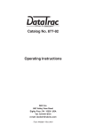
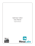
Defender™ 500 Series User Manual Driving a Higher Standard SM in Flow Measurement Table of Contents Introduction ..........................................................................1.0 Operation ..............................................................................2.0 Battery ................................................................................. 2.1 Activation ............................................................................. 2.2 Connections ......................................................................... 2.3 Display Screen ..................................................................... 2.4 Menu Navigation . ................................................................ 2.5 Set Up .................................................................................. 2.6 Measurements .................................................................... 2.7 Single ................................................................................... 2.8 Burst .................................................................................... 2.9 Continuous . ......................................................................... 2.10 Data Port . .............................................................................3.0 Optimizer Software . ............................................................ 3.1 SKC CalChek® Interface ...................................................... 3.2 Defender Firmware Upgrades ............................................ 3.3 Annual Maintenance and Calibration ....................................4.0 Shipping ................................................................................5.0 Storage .................................................................................6.0 Defender Specifications . ......................................................7.0 Default Settings ....................................................................8.0 Limited Warranty ..................................................................9.0 Troubleshooting . ..................................................................10.0 Introduction 1.0 Operation 2.0 Data Port 3.0 Annual Maintenance and Calibration 4.0 Shipping 5.0 Storage 6.0 Defender Specifications 7.0 Default Settings 8.0 Limited Warranty 9.0 Troubleshooting 10.0 1.0 Introduction 1.0 Display The Defender 510 measures volumetric gas flow with an accuracy of +/- 1% of reading. The Defender 520 measures volumetric gas flow with an accuracy of +/- 1% of reading and measures gas flow temperature and pressure. Both instruments use our proven DryCal® technology to measure volumetric gas flow and are produced in our accredited laboratory in Butler, N.J. This manual will provide the information needed to operate your Defender. If at any time you have questions regarding its operation, please contact Bios through our web site (www.biosint.com) or call us at 973.492.8400 to speak with a member of our professional customer service staff. Suction Fitting Measuring Cell Pressure Fitting Your Defender Your Defender comes with the following: • • • • • • AC Power Adapter/Charger Bios Optimizer Software CD PC Serial Cable Leak Test Caps (2); Save for use during the Leak Test Calibration Certificate Manual Carrying cases and accessories are available for purchase from Bios or your Bios distributor. 2 Data Port Charging Jack Calibration Label Reset Button Anti-tamper Label 3 2.0 Operation 2.0 2.1 Battery 2.2 Activation Charging, installing and monitoring your Defender battery Turning your Defender on and off Your Defender battery is charged at the factory, but we recommend that you make sure it is fully charged before initial use. Simply press the power button. • C onnect the AC power adapter to the Defender’s Charging Jack (DC In). • Plug the AC power adapter into an AC outlet. • P ress the On/Off button for 1 second to turn on your Defender. • When first turned on, your Defender displays an opening screen showing the product name, model number and flow range. • Press the On/Off button for 3 seconds to turn your Defender off. Initial charging should take about eight (8) hours. 2.3 Connections After the initial charge: • Y ou may continue to charge your Defender indefinitely simply by leaving it connected to the AC power adapter. • Be sure to charge the battery at least every three (3) months, to maintain battery life. Attaching your Defender to a device Connect device to be calibrated to the appropriate Defender port. Use 1/4 inch diameter tubing. • C onnect to outlet at top (suction fitting) when a device draws air (such as sampler). • Connection tubing to bottom inlet for devices that push air in (pressure devices). The battery symbol on the LCD display indicates your Defender’s battery charge condition. A shaded battery icon indicates a full charge. As the battery voltage drops, the indicator will empty in 20% increments. 4 5 2.4 Display Screen Understanding the screen components The Defender provides a menu of operational settings and commands. The four directional arrow buttons on the control panel allow you to navigate through the menu and select the desired settings for your Defender. Your location within the menu is highlighted for easy identification. 2.5 Menu Navigation Moving through operational menus • U se the directional arrows , , and on the control panel to find your way through the menu. • When your desired command is highlighted, simply press the ENTER button on the control panel. If you see a menu selection within angle brackets (<….>), that means you have multiple options for an item. Press the left or right (or ) arrow button to see the options. If you wish to use the factory settings proceed to section 2.7 Measurements. 2.0 Defender 520 M Range: 50–5,000 mL/min Control Panel with DryCal Technology® MEASURE | SETUP Defender LCD Screen On/Off Button 2.6 Set-up Customizing the Defender to your needs You can customize your Defender in the Setup menu. Highlight SETUP in the introduction screen to enter the Setup Menu. Or, highlight SETUP after resetting and then exiting a measurement mode screen. The Setup menu has eight submenus. To select a submenu, use the directional arrow buttons to highlight the submenu and press the Enter button. In submenus, brackets (i.e., <...>) indicate different selection options. You can switch back and forth by pressing the forward or backward (or ) arrow. Highlight CONFIRM after making changes and press the Enter button to save the changes made. 6 7 ‘Confirmed, New Settings Will be Retained’ message will appear in the screen for a brief period before it returns to Setup menu. Units Highlighting EXIT and then pressing the Enter button will return you to the SETUP menu without saving any submenu changes. In the Defender 520 model, measure Pressure in mmHg, kPa or PSI and Temperature in Celsius or Fahrenheit. Readings Time Choose the number of measurements in the average from 1 to 100. Set the current time and the format. If you wish to incorporate a time delay between consecutive measurements, set Time Between from 1 to 60 minutes. Measure gas Flow in cubic centimeters, milliliters, liters or cubic feet (all units are per minute). 2.0 The format can be selected as PM, AM, or 24H. Date Set the date and the format. The format can be selected as DD (day)-MM (month)-YYYY (year) or MM (month)-DD (day)-YYYY (year). 8 9 Power Power Save By selecting <On>, your Defender will save power by turning off after five minutes of inactivity. However, it will not turn off when connected to the AC power adapter/charger. Preferences Read Default Select a preferred mode of measurement when the Defender is initially turned on. 2.0 Select <Off>, and your Defender will remain on until you manually turn it off. Backlight Select <On> to illuminate the LCD display or <Off > to conserve battery power. Default Settings Select <No> to allow the ‘Read Default’ change. Selecting <Yes> will reset your Defender to the factory default settings. (Factory default settings are provided elsewhere in this manual.) Data Port Set the data port interface by selecting: <BIOS> to operate with Bios Optimizer software. <SKC> to operate with SKC CalCheck® Interface. Magnification In the Defender 520 model, this controls the amount of data on the display. Select <Zoom> to view only flow measurements in larger font, or select <Detail> to simultaneously view flow measurements, temperature, and pressure in a smaller font. 10 11 Diagnostics About The Defender Leak Test is designed only to verify the internal integrity of the instrument and alert you to an internal leak. We recommend performing the Leak Test only as an intermediate quality control check or whenever the integrity of the instrument is questioned due to misuse or accidental damage. This screen provides basic information about your Defender, which may be an especially helpful reference when speaking to a Bios technical support representative or your Bios distributor. Please note that a leak test is not a substitute for a comprehensive examination of the unit’s overall performance and it does not ensure that your Defender is operating accurately. Out of Range 2.0 If the flow you are measuring is outside the Defender’s flow range, (see section 7 Defender Specifications for ranges), the “Out of Range!” warning appears. Immediately lower or disconnect the flow. When the flow is within the proper range, select RESET to clear your Defender’s last measurement • I nvert your Defender and allow the piston to travel to the top • Cap the port under test using the Bios supplied leak test cap. Leave the other port uncapped. • Press Enter on the control panel while the unit is still inverted • Return the unit upright. The leak test will progress • If Defender leak test is unsuccessful, go to section 10 Troubleshooting. • When test is complete, select exit to return to main menu. 12 13 2.7 Measurements 2.0 Taking gas flow readings To maintain the best possible accuracy and minimize thermal effects, Bios recommends fully charging your battery before taking measurements. If this is not possible, we recommend disconnecting your Defender from its AC power adapter/charger while taking flow measurements — or to run gas through your Defender for 10 minutes before starting the flow measurement. First steps Press the power button. • P ress the On/Off button for 1 second to turn on your Defender. • When first turned on, your Defender displays an opening screen showing the product name, model number and flow range. • Press the On/Off button for 3 seconds to turn your Defender off. 2.8 Single Measurement Each time the ‘Enter’ button is pressed, one measurement will be made. When each subsequent measurement is made, the current flow and average of all prior readings will be displayed. 2.9 Burst Measurement This setting functions in the same manner as ‘SINGLE’, but measurements continue automatically until the preset number of measurements has been made. Operation then ceases, and the last reading and average are displayed. Press ‘Enter’ again to begin another preset sequence. Connect device to be calibrated to the appropriate Defender port. Use ¼ inch diameter tubing. • C onnect to outlet at top (suction fitting) when a device draws air (such as sampler). • Connect to inlet at bottom (pressure fitting) when a device pushes air. • Do not cap the unused port on the Defender. • Choose the measurement type, Single, Burst, or Continuous, then press enter. 14 2.10 Continuous Measurement This setting functions in the same manner as ‘BURST’, but new sequences will automatically repeat until stopped by the user. 15 3.0 Data Port 2.0 Note: (010 in series) indicates the number of measurements. 10 is the factory-preset number. Define the number of measurement you prefer, from 1 to 100, by accessing the SETUP menu. In Continuous or Burst mode, select: • P AUSE to terminate the current flow measurement but to leave the average flow measurement and previous flow measurement on the screen. This allows you to resume the flow measurement sequence if you wish to do so. • RESET to terminate the flow measurement and clear the screen. Interfacing with Optimizer and CalCheck ® ® Your Defender comes with a data port that provides a digital Interface for use with Bios Optimizer Software or with the SKC CalCheck® Interface. Visit www.biosint.com to find more information about Optimizer software, and for access to available Optimizer or Defender firmware upgrades. 3.0 3.1 Optimizer Software Your Defender is supplied with Bios Optimizer Collect light. Bios Optimizer Collect light captures flow data from your Defender directly to a Microsoft Excel® pre-configured spreadsheet. You can upgrade to Bios Optimizer Collect for more features such as hot key commends, instrument library, have multiple instruments interface simultaneously and much more. To run Optimizer Collect (upgraded version) or Collect light you must have Windows® XP, Windows® Vista (32 bit version), Microsoft Excel® 2000, 2003, 2007. See the Optimizer CD cover for installation instructions. 16 17 4.0 Annual Maintenance and Calibration 3.2 SKC CalCheck® Interface Assuring top performance and accuracy The Defender may be set to automatically calibrate SKC’s Airchek® 2000 and Leland Legacy pumps, with the purchase of a CalChek communications cable from SKC (for details please contact SKC at www.skcinc.com). On your Defender, set Setup>Preferences>Data Port to <SKC> highlight CONFIRM and press the Enter button before taking measurements. Your Defender is a precision measuring standard with moving parts machined to extremely close tolerances. Various environmental factors, product wear, drift of sensors, or inadvertent damage may adversely affect your Defender’s measurement accuracy or general performance. For these reasons, Bios highly recommends having your Defender annually verified by an ISO 17025–accredited laboratory, such as Bios, to ensure its measurement integrity. 3.3 Defender Firmware Upgrades The Defender firmware is upgradable through the Data Port. Firmware upgrades and procedures for your Defender are available online through our website (www.biosint.com). 3.0 4.0 For the ultimate in Defender maintenance and to take advantage of any available software and mechanical upgrades, Bios offers an annual non-mandatory Recertification program. This is a service package that provides complete product refurbishment, testing and available upgrades; calibration and NIST-traceable calibration certificates. Recertification includes a 90-day service warranty should any related labor or parts replacements prove faulty. Turnaround time is generally two weeks from time of receipt. Expedited 48-hour turnaround is available. 18 19 5.0 Shipping Tips and guidelines for sending your Defender to Bios Shipping If you are sending your Defender for repair or evaluation (rather than elective Recertification), contact Bios for technical support or troubleshooting assistance prior to shipping the unit. Provide us a detailed description of your issues. If we are unable to resolve the situation by phone or email, we will issue you an RMA (return merchandise authorization) number. Follow online instruction for proper return procedure. When shipping your Defender, be sure to follow some simple guidelines to avoid costly damage to your property. You can obtain an RMA number through our automated web-based system at http://www.biosint.com/contactUs/ rmaform.aspx. RMAs also can be obtained through email to [email protected], or by telephone at 973.492.8400. Our web site address is www.biosint.com. Note: Bios will not evaluate or service your instrument without an RMA number. • U se adequate packing material. Whenever possible, use the original packing that came with your Defender. Or use a Bios Pelican carrying case, which provides a hard case shell for protection of your valuable equipment. If you do not already have a Bios Pelican case, visit us at www.biosint.com for more information on obtaining one. • Use a major freight carrier (e.g., FedEx, UPS) that supplies tracking numbers. • Insure your Defender. Bios is not responsible for damage occurred during transit. • Understand our mutual shipping obligations. Bios is responsible for shipping cost only if the issue is product related and the Defender is still under warranty. 5.0 If we find the issues you have identified are application related and not product related, an evaluation fee will be charged. 20 21 6.0 Storage 7.0 Defender Specifications Protecting your Defender when not in use Technical data about your Defender If you need to store your Defender for an extended period, please follow these guidelines: Models: 510L/520L, from 5-500 mL/min 510M/520M, from 50-5,000 mL/min 510H/520H, from 300-30,000 mL/min • A lways store it in a clean, dry place. • If possible, leave it attached to its AC power adapter/charger while in storage. • If your Defender cannot be attached to its AC power adapter/ charger while in storage, please do the following: – F ully charge it before extended storage. If the battery is not fully charged prior to storage, it might be permanently damaged. • Fully charge it at least once every three months. • Recharge the battery for at least 8 hours prior to reusing your Defender after storage. 22 Measurements: Volumetric Accuracy: ±1% of reading Time per Measurement: 1-15 seconds (approximate) Type: Single, Continuous or Burst Volumetric Flow Units: cc/min, mL/min, L/min, cf/min Pressure Units (Defender 520): mmHg, PSI, kPa Temperature Units (Defender 520): °C, °F Basics: Dimensions (H x W x D): 5.5 x 6 x 3 in / 140 x 150 x 75 mm Weight: 29 oz / 820 g Configuration: Integrated flow measuring cell, valve and timing mechanism Temperature & Pressure Sensors (Defender 520 model only): In the flow stream Press Accuracy: 3.5 mmHg (typical), 7.0 mm (max); Temp Accuracy: 0.8° C (typical), 1.3° C (max) AC Power Adapter/Charger: 12VDC, 250ma, 2.5 mm, center positive Port Tube Diameter: 1/4 in / 6.35 mm 6.0 7.0 23 8.0 Default Settings Battery: 6V rechargeable, sealed lead-acid, 6-8 hours typical operation Battery Operational Time (5 cycles/min): 3 hrs backlight on, 8 hrs backlight off Pressure & Suction Fittings: ¼” barbed tube fittings Display: Backlit graphical LCD Usage: Flow Modes: Suction or Pressure Operating Pressure (Absolute): 15 PSI Operating Temperature: 0-50° C Ambient Humidity: 0–70%, non-condensing Storage Temperature: 0–70 °C Warranty: 1 year; battery 6 months Bios Optimizer Software: Requires Windows Vista, Windows XP–SP2 or Windows 2000–SP3 compatible PC and RS-232 (serial) connection Original factory settings for your Defender The Defender is set with the following Default settings from the factory: • • • • • • • • • • • Flow Units – mL/min Number in Average – 10 Time Between – 0 Measurement Mode – Single Backlight – On Power Save – On Time Format – 24 hour Date Format – MM-DD-YYYY Temperature Units (Defender 520 only) – C Pressure Units (Defender 520 only) – mmHg Magnification (Defender 520 only) – Zoom 7.0 8.0 Bios Optimizer installation CD (supplied); no restrictions apply RS-232 cable (supplied) for Defender 500 Series data port to PC RS-232 (serial) port connection PC Card (optional and as necessary) creates an RS-232 port on your PC Licensed upgrade to Bios Optimizer Collect is available 24 25 9.0 Limited Warranty Outlining our responsibilities 2. When the serial number has been altered or removed The Bios Defender 500 Series is warranted to the original end user to be free from defects in materials and workmanship under normal use and service for a period of one year from the date of purchase as shown on the purchaser’s receipt. The Defender 500 Series’ battery is warranted for six months from the original purchase date. If the unit was purchased from an authorized reseller, a copy of an invoice or packing slip showing the date of purchase may be required to obtain warranty service. 3.That has been repaired, altered or maintained by any person or party other than Bios International Corporation’s own service facility or a Bios authorized service center, should one be established. The obligation of Bios International Corporation under this warranty shall be limited to repair or replacement (at our option), during the warranty period, of any part that proves defective in material or workmanship under normal use and service, provided the product is returned to Bios International Corporation, transportation charges prepaid. This warranty is in lieu of all other warranties and all other obligations or liabilities arising as a result of any defect or deficiency of the product, whether in contract or in tort or otherwise. All other warranties, expressed or implied, including any implied warranties of merchantability and fitness for a particular purpose, are specifically excluded. In no event shall Bios be liable for any special, incidental or consequential damages for breach of this or any other warranty, express or implied whatsoever. Notwithstanding the foregoing, Bios International Corporation shall have no liability to repair or replace any Bios International Corporation product: 9.0 1.That has been damaged following sale, including but not limited to damage resulting from improper electrical voltages or currents, defacement, misuse, abuse, neglect, accident, fire, flood, terrorism, act of God or use in violation of the instructions furnished by Bios International Corporation 26 27 10.0 Troubleshooting Answers to common operational questions Bios is ready to help you with any operational issue you may encounter with your Defender. But we may be able to save you some time by providing a short checklist of the questions most commonly asked of our customer service and technical specialists. Why won’t my Defender turn on? If the Defender will not turn on, verify that the battery has been charged. When connected to the AC power adapter/charger and power is present a small green indicator light should be visible through the front viewing window My Defender won’t respond to push-button commands. If the Defender fails to respond to push-button commands, you can perform a hard reset of the Defender. This can be done by inserting a paper clip into the reset opening in the back of the unit. I’m not sure I have my Defender connected properly. Verify that the flow source is connected to the pressure port of your Defender for pressure sources or to the suction port for verifying suction pumps. The unused port should be at atmospheric pressure with any cap or plug removed. If you are calibrating a gas that requires an exhaust line to vent the measurement gas, ensure that the tubing is of sufficient diameter not to create a pressure drop greater then 5 inches of water. 28 How do I protect against leaks? Ensure that hose and tube fittings are tight and leak free. The tubing connecting your flow source (pump, mass flow controller, needle valve, sonic nozzle or restrictor) to the meter should be kept as short as possible. What do I do when my leak test fails? First check to make sure that the leak test cap is on correctly and it is not leaking through the leak test cap itself. If the leak test cap is correct perform leak test both at the pressure and suction side. If it fails, contact Bios Technical Support. What’s the best way to connect to the filter medium? When calibrating sampling pumps best results are obtained with the filter medium connected to the pump and the Defender connected to the inlet side of the filter medium with a short piece of tubing. 10.0 29 Why am I experiencing a temperature increase in my Defender 520? A temperature rise during initial battery charging, or while charging a fully discharged battery is normal. To maintain the best possible accuracy Bios recommends fully charging your battery before taking measurements. If this is not possible, we recommend disconnecting your Defender from its AC power adapter/charger while taking flow measurements – or to run gas through your Defender for 10 minutes before starting the flow measurement. What is Dead Volume ? Dead Volume is the gas volume between a flow generator and the instrument taking the measurement. Since gas is compressible, this gas can act as a spring between the flow source and the measurement instrument. For best accuracy this volume should be kept to a minimum. We recommend keeping the tubing length between the gas flow generator and your Defender to no more then .5 meters/20 inches in length. Why doesn’t my piston return to the bottom of the cell? If the piston fails to return to the bottom of the cell after a measurement this could be caused by: • A discharged battery not providing enough power to operate the internal valve properly (Try charging the Defender) • Bright light shining into the unit resulting in an overload of the internal optical sensors (Try to operate the unit in a shaded location) • Moisture or dirt inside the cell (Return the Defender to Bios for service) 10.0 30 31 Driving a Higher Standard SM Bios Corporation in FlowInternational Measurement 10 Park Place Butler, NJ, USA 07405 Phone: 973.492.8400 Toll Free: 800.663.4977 Fax: 973.492.8270 Email: [email protected] web: www.biosint.com © 2009 Bios International Corporation MK01-24 REV D