1
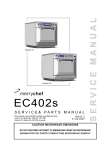
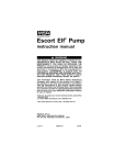
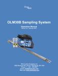
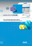
Operating Instructions (Condensed Version) For more detailed instructions see User Manual. SKC Inc. 863 Valley View Road Eighty Four, PA 15330 USA Form #37740 Rev 0611 Table of Contents Description............................................................................................................................. 1 Performance Profile.............................................................................................................. 2 Setup....................................................................................................................................... 4 Turning the Pump On/Off................................................................................................ 4 Keypad Basics................................................................................................................ 4 Entering/Navigating the User Interface........................................................................... 4 Resetting Run Time Data............................................................................................... 5 Scrolling Through Run Time Data.................................................................................. 5 Checking Battery Condition............................................................................................ 5 Setting Pump Flow Rate................................................................................................. 5 Setting a Sampling Time (S1-)......................................................................................... 6 Deleting a Sampling Time (S1-)....................................................................................... 7 Setting a Delayed Start................................................................................................... 7 Changing the Data Display............................................................................................. 7 Calibration.............................................................................................................................. 8 Verifying Flow Rate Using a Primary Standard Calibrator.............................................. 8 Calibrating Using CalChek.............................................................................................. 8 Sampling................................................................................................................................ 9 Sampling (1000 to 3250 ml/min)..................................................................................... 9 Flow Fault....................................................................................................................... 9 Programming....................................................................................................................... 10 Battery Operation................................................................................................................ 11 Battery Condition.......................................................................................................... 11 Charging the Battery Pack............................................................................................ 11 Replacing the Battery Pack.......................................................................................... 12 NiCad Battery Notes..................................................................................................... 13 Technical Note: Battery Pack Life................................................................................. 13 Continuous Operation Using Battery Eliminator........................................................... 13 Service.................................................................................................................................. 14 Service Policy............................................................................................................... 14 Accessories......................................................................................................................... 15 UL Certificate....................................................................................................................... 17 Warranty............................................................................................................................... 18 Indicates a warning or caution. For AirChek 2000 operating instructions in Spanish and French, visit www.skcinc.com. Notice: This operating instruction may not address all safety concerns (if any) associated with this product and its use. The user is responsible for determining and following the appropriate safety and health practices and regulatory limitations (if any) before using the product. The information contained in this document should not be construed as legal advice, opinion, or as a final authority on legal or regulatory procedures. Operation AirChek 2000 Quick Guide Star Button Scrolls through run time data, display options, and sampling parameters during pump setup Up and Down Arrow Buttons Increase or decrease sampling parameters and toggle between display choices in setup Button Sequence = press buttons individually [] = press simultaneously when bracketed = security code, always press in sequence Pump Activation Press any button. Security Code Must be pressed within 10 seconds of previous command Mode Change Press [] to toggle between Run and Hold. Pump Setup Options Options for Flow Rate To enter flow options, pump must be in Hold. Press [] to Run pump and press all within 10 seconds. • Change and calibrate flow rate: Flow rate and SET flash. Press or to change flow rate. Press when finished; ADJ displays and flashes. Press or to adjust the flow until pump and calibrator agree. When finished, press until End displays. Press [] to save new setting. Options for Programming/Display To enter programming/display options, pump must be in Run. Press [] to Hold pump and press all within 10 seconds. • Clear accumulated data: Press until CLr displays and then press []. Press until End displays and then press []. • Change temperature scale (F/C): Press until temperature displays. Press or to switch units. Press until End displays and then press [] to save new setting. • Change atmospheric pressure scale (mm Hg/ins Hg/millibars): Press until pressure displays. Press or to switch units. Press until End displays and then press [] to save new setting. • Change time scale (12-Hr/24-Hr): Press until 12 Hr or 24 Hr displays. Press or to switch units. Press until End displays and then press [] to save new setting. • Change time of day: Press until time displays. Press or to change flashing hour. Press to move to minutes and press or to change. Press until End displays and then press [] to save new setting. • Change sampling time: Press until S 1- 00 displays. Press or to change flashing digits. Press until End displays and then press [] to save new setting. Description Your new SKC AirChek® 2000 Pump is an advanced programmable sample pump that combines lightweight compact design, computer-compatible circuitry, and an internal flow sensor. The result of extensive research and development, the AirChek 2000 Pump exemplifies SKC’s commitment to quality and innovation in air sampling equipment. Inlet Port with Protective Filter Battery Status Icon Flashing LED Run Indicator Liquid Crystal Display (LCD) Keypad with Operating Buttons Battery Pack Not shown: Beltclip (back) Battery Charging Jack (back) Computer Interface Port (back) AirChek 2000 Air Sampling Pump Performance Profile Flow Range: 1000 to 3250 ml/min (5 to 500 ml/min requires optional low flow adapter kit) Compensation Range: 3000 ml/min at 15 inches water back pressure 2500 ml/min at 20 inches water back pressure 2000 ml/min at 30 inches water back pressure 1000 ml/min at 30 inches water back pressure Typical Back Pressure of Sampling Media (inches water) Flow Rate (L/min) Filter/Pore Size (µm) 25-mm MCE/0.8 37-mm MCE/0.8 37-mm PVC/5.0 1.0 1.5 2.0 2.5 3.0 6 2 1 9 3 1 12 4 2 15 5 2 18 6 2.5 Compare the information in this table to pump compensation range to determine appropriate applications. Accuracies: Timing: 1 min/month @ 25 C Atmospheric Pressure: ± 0.3 inches Hg Flow Rate: ± 3% of set-point after calibration to desired flow Battery Charge Level Indicator: Icon displays at full, mid, and low charge Temperature Range: Operating: Charging: Storage: 32 to 113 F (0 to 45 C) 32 to 113 F (0 to 45 C) -4 to 113 F (-20 to 45 C) Protect sample pump from weather when in use outdoors. Altitude: Do not use pump beyond 7500 ft. Run Time: With battery pack, run time is 10 hours for 2000 ml/min and up to 30 inches back pressure. Dependent on sample media used. See Table 1. Timer Display Range: 1 to 9999 minutes (6.8 days). If the run time exceeds 6.8 days, the timer display rolls over to 1. Times greater than 9999 minutes are only displayed on a PC using DataTrac 2000 Software. Time Display: Time-of-day in hours and minutes (12- or 24-hour clock) with AM and PM indicators. Flow Fault: If flow drops by more than 5%, pump stops and holds historical data. After 5 minutes in fault, auto-restart is attempted every 5 minutes up to 10 times. Performance Profile Battery Pack: Removable battery pack with rechargeable NiCad battery, 4.8 V, 2.0 Ah capacity. Size: 5.6 x 3 x 2.3 (14.2 x 7.6 x 5.8 cm) Weight: 22 oz (624 gm) RFI/EMI Shielding: RFI/EMI-shielded case, CE approved (Models 210-2002 and 210-2002Ex) Intrinsic Safety: UL and cUL Listed (Model 210-2002); CENELEC approved IS to EEx ia IIB T4 (Model 210-2002Ex) Use only SKC-approved parts to ensure reliable performance and intrinsic safety and to maintain the SKC warranty. Table 1. AirChek 2000 Run Time in Hours with NiCad Battery Following are typical run times achieved when using a fully charged NickelCadmium (NiCad) battery pack. Data is sorted by type of sample media. All run times are listed in hours. Results obtained using a new pump and new fully charged battery. Pump performance may vary. Mixed Cellulose (MCE) filter, 0.8 µm pore size Filter Diameter Flow Rate (L/min) 37 mm 25 mm 2.0 24.2 15.2 2.5 20.4 12.4 3.0 17.7 ** Polyvinyl Chloride (PVC) filter, 5.0 µm pore size Filter Diameter Flow Rate (L/min) 37 mm 25 mm 2.0 28.2 21.8 2.5 27.0 22.0 3.0 22.6 18.2 ** Filter back pressure exceeded pump capability during testing Note Increases in back pressure during sampling due to buildup of sample on the filter can decrease battery life. Setup Turning the Pump On/Off • Press firmly to turn the power on. • Press [] to run the pump or to place a running pump in HOLD mode. • Auto OFF turns the pump off after five minutes in HOLD mode. Keypad Basics The AirChek 2000 Pump operates by pressing various button sequences on the keypad located on the front of the pump housing. Scrolls through run time data and Setup options. Increases values such as flow rate. Decreases values such as flow rate. [] When pressed simultaneously, displayed item is selected or entered. Security code that must be pressed in sequence after mode change all within 10 seconds to enter the User Interface. If the 10-second time limit is exceeded, the pump will remain in its current mode. Perform steps again to enter the User Interface. Entering and Navigating the User Interface The AirChek 2000 User Interface features two levels. Level One allows the user to change flow rate, adjust flow rate to a primary standard, or calibrate the pump using the CalChek feature. Level Two permits the user to change display options, i.e. temperature (F or C), atmospheric pressure (ins, m, or mm), set a sampling time, set 12- or 24-hour clock or delayed start, set real time clock, or clear accumulated run time data. Entering: • With pump in HOLD, press [] to place pump in RUN and enter all within 10 seconds. You are in Level One of the User Interface. • With pump in RUN, press [] to place pump in HOLD and enter all within 10 seconds. You are in Level Two of the User Interface. Navigating: Press to scroll through parameters. Once LCD shows End, parameters will repeat until the user exits the User Interface. Setup Exiting: Press until End appears on the LCD. Press []. Any changes made to parameters will be saved and the pump will continue in its current mode. Level Two of the User Interface offers the option of exiting without saving changes to parameters. Press until Esc appears on the LCD. Press []. Resetting Run Time Data 1. With the pump running, press [] to place the pump in HOLD mode and enter all within 10 seconds. You are in Level Two of the User Interface. 2. Repeatedly press until CLr appears on the display. 3. Press [] and then press until End appears. 4. Press []. The accumulated data is cleared and the pump is now in HOLD mode. Note CLr does not clear previously set sampling time (S1-). See Deleting a Sampling Time on p. 7. Scrolling Through Run Time Data Repeatedly press to view flow rate, sample volume, temperature, time-ofday, atmospheric pressure, and run time. Checking Battery Condition See page 12. Setting Pump Flow Rate 1. With the pump in HOLD mode, press [] to run the pump and enter all within 10 seconds. You are in Level One of the User Interface. 2. The flow rate on the LCD will flash. Press to increase flow rate. Press to decrease flow rate. 3. Once the desired flow rate is displayed, press repeatedly until End appears on the display. 4. Press [] to save the flow rate. 5. Press [] again to place the pump in HOLD mode. Setup Setting Sampling Time (S 1-) Program the AirChek 2000 from the keypad or a PC to run STEL, TWA, or any other run time from 1 to 999 minutes. To program a sampling time using the pump keypad: 1. 2. 3. 4. 5. 6. 7. With the pump running, press [] to place the pump in HOLD mode and enter all within 10 seconds. You are in Level Two of the User Interface. Repeatedly press until S 1- and a flashing 00 appear on the display. Set the sampling time by pressing to increase it or to decrease it to the desired time in minutes. Press repeatedly until End appears. Press [] to save the sampling time and exit the User Interface. A flashing “S” will appear with the selected sampling time on the LCD. Press [] to begin sampling. The time display will count down in minutes, the pump will go into HOLD mode, and the total sampling time will display when sampling is complete. To delete a set sampling time, enter Level Two of the User Interface, scroll to S I-, and press until time appears as 00. Exit the User Interface by scrolling to End and pressing []. Note A time still appears on the display after canceling a sample time. This is total run time since the data was last cleared. Note If a sampling time (S 1-) has been programmed into the pump, a DataTrac® 2000 program cannot be entered without deleting a sampling time first (see page 7). Likewise, if a DataTrac 2000 program resides in pump memory, the sampling time (S 1-) function cannot be selected until the DataTrac program is deleted (see User Manual). Setup Deleting a Sampling Time (S1-) To delete the S 1- period, enter Level Two of the User Interface and press the button to scroll to S 1-. Press until 00 displays. Press the button until End appears. Press []. Setting a Delayed Start The Delayed Start feature is available in AirChek 2000 pumps version 2.59 or higher. See User Manual for instructions. Changing the Data Display The data display has been factory-set for Celsius (temperature units), millimeters of mercury (pressure units), and 12-hr (clock). These units can be changed. See User Manual for instructions. Calibration Verifying Flow Rate Using a Primary Standard Calibrator 1. Connect the pump inlet to a calibrator with representative sample medium in-line. To ensure sample integrity, tubing fits tightly onto the pump inlet filter cover. Use care when removing tubing to prevent cracking or breakage of the inlet filter cover. 2. With the pump in HOLD mode, press [] to run the pump and enter all within 10 seconds. You are in Level One of the User Interface. The flow rate and SET icon will display and flash. 3. Set the flow on the pump by pressing to increase it, or to decrease it to the desired flow rate. 4. Press . A flashing ADJ and 0 appear. 5. If the calibrator reads a higher flow rate than the pump was set for, press until they are in agreement (within 10 ml). If the calibrator reads a lower flow rate, press until they agree (within 10 ml). When pressing or , the pump display will indicate the adjustment (or correction) made in ml/min. 6. Press until End appears. 7. Press []. Reset run time data (see p. 5). Note If a delayed start or DataTrac 2000 schedule has been programmed into the pump, it may remain in pump memory. PROG will display in the upper left corner of the pump display. To delete this program, see User Manual. Calibrating the AirChek 2000 Pump Using the CalChek Automatic Calibration Feature The CalChek automatic calibration feature is available when calibrating an AirChek 2000 pump (version 2.59 or higher) with DC-Lite Calibrator model 717-01 (10 ml/min to 12 L/min). A CalChek Communicator adapter is required for communication between the pump and the calibrator. Optional DataTrac 2000 Software (version 3.59 or higher) can be used to expand the documentation capabilities of this system. The CalChek feature provides two calibration options: single point calibration allows you to set and verify a flow rate at a single point before and after sampling; full (multiple point) calibration calibrates the flow to a primary standard at multiple flow rates. Both bring the flow to within 5%. See User Manual for instructions. Note If using a pump version below 2.59, a pump upgrade is required to use the CalChek feature. For low flow calibration and sampling instructions, see the User Manual. Sampling Sampling (1000 to 3250 ml/min) 1. Following calibration, replace representative sampling medium with a new unexposed medium. Protect sample pump from weather when in use outdoors. 2. To begin sampling, press [] to RUN the pump. Record the start time. 3. Sample for the time specified in the method used. 4. To stop sampling, press [] to HOLD the pump. Record the stop time. 5. When sampling is complete, pump data is retained in memory for recovery. Data can be viewed on the LCD by using the button to scroll through it. When using impingers, place an in-line trap between the pump and the impinger to protect the pump from harmful liquids or vapors. Failure to use the impinger trap voids the pump warranty. Note If a delayed start or DataTrac 2000 schedule has been programmed into the pump, it may remain in pump memory. PROG will display in the upper left corner of the pump display. To delete this program, see the User Manual. To ensure sample integrity, tubing fits tightly onto the pump inlet filter cover. Use care when removing tubing to prevent cracking or breakage of the inlet filter cover. For low flow sampling (5 to 500 ml/min), see the User Manual. Flow Fault If flow drops by more than 5%, the pump goes into HOLD mode and retains historical data. The flow fault icon flashes during flow fault. The pump will restart in five minutes and try to continue sampling. If the flow remains restricted, the pump returns to flow fault. Auto-restart is attempted every five minutes up to 10 times. Flow fault time is not added to the displayed run time or cumulative volume display. Programming See User Manual for programming the pump using a PC. 10 Battery Operation Battery Condition Three bars indicate a full charge (normally appears after charging), approximately 75% to 100%. Two bars indicate that the battery is charged enough to operate the pump, approximately 25% to 75%. One bar indicates battery charge is low (charge battery), approximately 1% to 25%. Low Battery Fault No bars and a flashing outline indicate a Low Battery Fault mode (pump will go into HOLD mode). Note When the pump stops due to a low battery and is left to stand for a period of time, one battery bar may appear. This false “recovery” will fall quickly if the pump is operated without recharging it. RECHARGE THE PUMP BEFORE SAMPLING. Using a non-approved charger voids the SKC warranty. For more information on Battery Care and Maintenance, see the AirChek 2000 User Manual. Charging the Battery Pack To charge the battery, plug the charger into a standard wall outlet. Insert the charging plug from the charger into the battery charging jack on the back of the pump. The fast charging function of the battery pack will recharge the battery in approximately 6 hours or less. For optimum performance, use a charger that does not promote memory effect ( see Accessories on p. 16). Follow charger instructions. Using a non-approved charger voids the SKC warranty. Tampering with the battery pack voids the SKC warranty, the UL Intrinsic Safety listing (model 210-2002), and the CENELEC approval for model 210-2002EX. Do not charge in hazardous environments. Ensure that the computer interface port is covered before and during charging. . 11 Computer Interface Port Battery Charging Jack Battery Operation Replacing the Battery Pack To enhance battery life, SKC ships battery packs uncharged and separate from the pump. Once installed, completely charge battery pack before operating pump. Battery Replacement Notes: • To retain pump history, ensure the pump has been allowed to go to sleep after the last run. Pump history will be lost if the battery pack or AC power (battery eliminator) is removed while the pump is running. SKC recommends that data be downloaded to a PC using DataTrac 2000 Software prior to removal of the battery or power. • The first 8 program steps will be retained in memory. Programs should be reloaded using DataTrac® 2000 Software after replacing the battery pack. 1. Release the battery pack by removing the two security screws located on the bottom of the battery pack. Pull the battery pack away from the pump body. 2. Carefully align the battery jack on the replacement battery pack with the battery terminal on the bottom of the pump base plate and push the battery pack into place. 3. Replace and tighten the two security screws removed in step 1. Battery terminal Battery jack Pump base plate Battery pack Use of a repaired or rebuilt battery pack voids the SKC warranty and the UL Intrinsic Safety Listing. Do not charge or operate the pump with charger in hazardous atmospheres! Use only an SKC-approved charger and battery pack designed for the AirChek 2000 Sample Pump to ensure reliable performance and intrinsic safety and to maintain the SKC warranty. 12 Battery Operation NiCad Battery Notes and Recommended Maintenance • NiCad batteries self-discharge at an average rate of 18 to 20% per month at room temperature. The rate of self-discharge increases with temperature. Ultimately, self-discharge results in an increased need for charging. Recommended Maintenance: • Cycle battery use on a monthly basis (quarterly for pumps not used on a regular basis). • “Exercise” your battery pack! Use an SKC battery conditioning system (MasterCharger® or PowerFlex®) that automatically exercises batteries. Perform this procedure before storage and monthly (quarterly for pumps not used on a regular basis). • Store and charge batteries in the recommended temperature range. • Discharge and recharge battery packs fully before use and storage. • Stated battery capacity will not be reached “right out of the box,” but only after the battery is exercised. Often new NiCad battery packs require 5 to 7 cycles to reach the stated capacity. Recommended Maintenance: “Exercise” your battery! Use an SKC battery conditioning system (MasterCharger or PowerFlex) that automatically exercises batteries. Perform this procedure before storage and monthly (quarterly for pumps not used on a regular basis). • Battery packs are typically shipped less than fully charged to meet testing and shipping requirements. Recommended Maintenance: Discharge and recharge battery packs fully before use and storage. • A NiCad battery should not sit on a charger for long periods of time. Recommended Maintenance: Remove battery pack from its charger within 24 to 48 hours after charging is complete. For further information on Maintaining NiCad Battery Packs, request SKC Publication 1363 (available for download at www.skcinc.com). Technical Note: Battery Pack Life • Battery manufacturers typically indicate expected battery life as the number of usable cycles within an approximate number of years (e.g., 300 charge/discharge cycles or 3 years). • The number of usable cycles/years of useful life for a battery pack is determined by the number of cycles/amount of time it takes for the battery to decline to 80% of its initial capacity when used under ideal conditions. The battery should be replaced at this point. • Battery life ratings are nominal (±5%) and are generally based on ideal conditions of use such as those in which they are tested (for testing criteria, see IEC 61436 and IEC 61951 test methods at www.iec.ch). • Individual conditions of use, charging procedures, and applications (high versus low current drain, intermittent versus steady current drain) may affect battery life. • While nickel-metal hydride (NiMH) batteries provide longer run times than NiCad batteries on a single charge, the user can expect less cycles life from an NiMH battery when compared to NiCad cycles life. Continuous Operation Using Battery Eliminator Continuous pump operation is possible in non-hazardous environments using the pump with a battery eliminator plugged into a wall outlet. See Accessories on p. 16. See the AirChek 2000 User Manual or contact SKC Technical Support at 724-941-9701 for details. 13 Service Service Policy To return products to SKC for servicing: 1. Call 800-752-8472 (724-941-9701 for international customers) to obtain a Return Materials Authorization (RMA) number and Product Decontamination Form. 2. Carefully package the product. Mark the RMA number on any correspondence relating to the return and on the outside of the package. 3. Ship to SKC, freight prepaid, to the following address: SKC Inc. National Service Center 863 Valley View Road Eighty Four, PA 15330 Package product carefully to prevent damage during transit. Include a contact name, phone number, shipping address, RMA number, and a brief description of the problem. For nonwarranty repairs, a purchase order number and billing address are also required. The Service Department will contact nonwarranty customers with an estimate before proceeding with repairs. Note SKC Inc. will accept for repair any SKC product that is not contaminated with hazardous materials. Products determined to be contaminated will be returned unserviced. Intrinsic safety and other approvals are void if SKC pumps are not repaired by SKC or authorized SKC repair centers. Use only SKC-approved parts to ensure reliable performance and intrinsic safety and to maintain the SKC warranty. 14 Accessories Description Cat. No. CalChek Communicator Adapter 210-501 DC-Lite Calibrator, 10 ml/min to 12 L/min flow range, includes charger and tubing 717-01 Chargers PowerFlex Charging System for SKC Personal Pumps 5-station, 100 - 240 V Single, 120 V Single, 100 - 240 V Battery Eliminator, for continuous run using AC-line operation 223-1000 223-2000 223-2000B 223-320 Protective Pouches Black Red, for high visibility Black, sound reducing 224-88 224-96A 224-96C DataTrac 2000 Software Package Includes software, adapter, and cable 877-91 Low Flow Adapter Kit (5-500 ml/min) Includes Constant Pressure Controller (CPC), Adjustable Low Flow Tube Holder, and Type A Protective Cover 210-500 Constant Pressure Controller (CPC) for sampling in the 5-500 ml/min flow range. Use with Adjustable Low Flow Holder (below). 224-26-CPC Adjustable Low Flow Tube Holders for Constant Pressure (Low Flow 5 to 500 ml/min) Applications (requires separate tube cover listed below) Single Dual Tri Quad Sample Tube Protective Covers (for adjustable flow tube holders listed above) Type A (tubes 6-mm OD x 70-mm L) Type B (tubes 8-mm OD x 110-mm L) Type C (tubes 10-mm OD x 150-mm L) Type T (tandem for color detector tubes up to 115-mm long and a trap tube) 15 224-26-01 224-26-02 224-26-03 224-26-04 224-29A 224-29B 224-29C 224-29T Accessories Description Cat. No. Replacement Parts Battery Pack Battery Pack (CE approved; for model 210-2002Ex) Belt Clip Case Case with interface for PC board in place Charging Jack Cover, Battery Pack Filter (inlet)/O-ring (3) Filter Housing Filters, inlet (50) Gasket Set Keypad Stack PC Board PC Board Interface Cover, Port Keypad Screw/Gasket Kit Valve Assembly, Bottom Valve Assembly, Top P20136 P21113 P20139 P20137 P20137A P20145 P20144 P20140 P20142 P40011 P21273 P79361 P20138 P79519 P79543 P20179 P79361 P21002 P21272 P21322 Long-duration Detector Tube Accessories: Trap Tubes Tandem Protective Tube Cover 222-3D-2 224-29T 16 17 SKC INC. LIMITED ONE YEAR WARRANTY 1. SKC warrants that its instruments provided for industrial hygiene, environmental, gas analysis, and safety and health applications are free from defects in workmanship and materials under normal and proper use in accordance with operating instructions provided with said instruments. The term of this warranty begins on the date the instrument is delivered to the buyer and continues for a period of one (1) year. This warranty does not cover claims due to abuse, misuse, neglect, alteration, accident, or use in application for which the instrument was neither designed nor approved by SKC Inc. This warranty does not cover the buyer’s failure to provide for normal maintenance, or improper selection or misapplication. This warranty shall further be void if changes or adjustments to the instrument are made by other than an employee of the seller, or if the operating instructions furnished at the time of installation are not complied with. 2. SKC Inc. hereby disclaims all warranties either expressed or implied, including any implied warranties of merchantability or fitness for a particular purpose, and neither assumes nor authorizes any other person to assume for it any liability in connection with the sale of these instruments. No description of the goods being sold has been made a part of the basis of the bargain or has created or amounted to an express warranty that the goods will conform to any such description. Buyer shall not be entitled to recover from SKC Inc. any consequential damages, damages to property, damages for loss of use, loss of time, loss of profits, loss of income, or other incidental damages. Nor shall buyer be entitled to recover from SKC Inc. any consequential damages resulting from defect of the instrument including, but not limited to, any recovery under section 402A of the Restatement, Second of Torts. 3. This warranty extends only to the original purchaser of the warranted instrument during the term of the warranty. The buyer may be required to present proof of purchase in the form of a paid receipt for the instrument. 4. This warranty covers the instrument purchased and each of its component parts. 5. In the event of a defect, malfunction, or other failure of the instrument not caused by any misuse or damage to the instrument while in possession of the buyer, SKC Inc. will remedy the failure or defect without charge to the buyer. The remedy will consist of service or replacement of the instrument. SKC Inc. may elect refund of the purchase price if unable to provide replacement and repair is not commercially practicable. 6. (a) To obtain performance of any obligation under this warranty, the buyer shall return the instrument, freight prepaid, to SKC Inc., at the following address: SKC Inc., National Service Center 863 Valley View Road Eighty Four, PA 15330 USA (b) To obtain return authorization information or for further information on the warranty performance you may telephone 724-941-9701 at the above address. See Service Policy section in operating manual (if applicable). 7. This warranty shall be construed under the laws of the Commonwealth of Pennsylvania which shall be deemed to be the situs of the contract for purchase of SKC Inc. instruments. 8. No other warranty is given by SKC Inc. in conjunction with this sale. Form #3755 Rev 0207 18