1
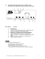
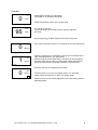
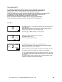
Operating Instructions
Bühler Shakers
Edmund Bühler GmbH ALLGEM\BED.SMG/BEDSME/TXTE.DOC – 01/08
1
Table of Contents .................................................................................................. 2
General Notes ...................................................................................................... 3
1.0 General Notes Concerning Areas of Application and Mode of
Operation...................................................................................................... 4
2.0 Transport Instructions .................................................................................. 5
3.0 Installation and Connection .......................................................................... 5
4.0 Operating the Models................................................................................... 6
4.1 KM 2, KL 2, KS 15 A/B, WS 10, TL 10, TiMix 2/5, SM A/B/C....................... 6
4.2 KS 15 A/B control, TiMix 5 control,
SM 30 A/B/C control, VKS 75 A/B control... ................................................. 7
4.3 Changing the Motion of KL 2, SM 30 C and TL 10....................................... 16
4.3.1 Change of the Angle of Inclination (Orbital Shaker TL 10)……………………17
4.4 Adjustment of the Counterweight (TiMix 5 / TiMix 5 control) ....................... 17
4.5 Exchange of the Rack Systems of KS 15, TiMix 2 and TiMix 5.................... 19
4.6 Fastening Multi-Storey Rack Systems to Shakers WS 10 / TL 10,
SM 30, VKS 75............................................................................................. 19
5.0 Maintenance and Servicing Instructions....................................................... 21
5.1 Exchange of the Fuse .................................................................................. 21
5.2. Motor Protection........................................................................................... 21
6.0 CE Declaration of Conformity....................................................................... 22
7.0 Warranty ...................................................................................................... 22
Technical Data...................................................................................................... 23
Basic Equipment / Accessories (Rack Systems) ............................................... 24 ff
Edmund Bühler GmbH ALLGEM\BED.SMG/BEDSME/TXTE.DOC – 01/08
2
General Notes
Dear customer,
Thank you for choosing a Bühler high-quality product for supporting you in your work.
The Bühler shakers were developed for the use in laboratories.
If you pay attention to the following points, the device will reward you with long life and
optimal operation.
1) Read the operating instructions carefully before initial operation.
2) The user must acquaint himself with the safety instructions and operating
conditions in order to avoid damage / injuries to material and personnel.
3) Liability and all claims under warranty end immediately in case of damages
which result from misuse and / or abuse.
4) The devices were carefully checked for perfect functioning and condition before
delivery.
5) Necessary servicing or repair work may only be done by personnel of the
Edmund Bühler GmbH technical service department, their authorized agents or
personnel trained by Edmund Bühler GmbH.
6) For shipping, the device must be adequately and safely packed. If possible, use
the original packing.
7) If the device is returned to Edmund Bühler for repair, it should be cleaned and
free of any harmful substances or residues.
These operating instructions are protected by copyright.
Edmund Bühler GmbH ALLGEM\BED.SMG/BEDSME/TXTE.DOC – 01/08
3
1.0 General Notes Concerning Areas of Application and Mode of Operation
The devices can be used in all laboratory fields in which it is necessary to mix and shake
homogeneously under constant and defined conditions.
Areas of Application (Examples):
• Homogeneous mixing of different liquids as well as of solid and liquid components
(e.g. nutrient solutions)
• Shaking of kits for diagnostic tracing reactions
• Solvent extraction of different phases in separating funnels for chemical
investigations
• Evenly changing agitation of liquid phase (nutrient solutions) or gaseous phase
(cell culture in Petri dishes)
• Coloring and decoloring of gels
Thanks to their different motions and high loading capacities, and especially their
variable "Combifix" rack systems, the Bühler shakers of the Edmund Bühler GmbH offer
solutions both for general as well as for individual shaking tasks.
For keeping the samples at constant temperatures, the shakers models KS 15, SM 30
and TiMix 5 can be equipped with an incubator hood. Temperature range: +5° C above
room temperature up to +50°C; a cooling coil for connection of an external flow-through
cooler is available as an option (TH 30).
Incubator Hood TH 30
Order No. 6162 000
Incubator Hood TH 15
Order No. 6161 000
In case of enquiries please contact the Export Sales Department
(Tel: +49 7471 9864-22; Fax: +49 7471 9864-75).
Edmund Bühler GmbH ALLGEM\BED.SMG/BEDSME/TXTE.DOC – 01/08
4
2.0 Transportation Instructions
Safe transportation of the devices is only ensured if original packaging is used. If they
are bumped hard or put down roughly, damages can occur.
ATTENTION:Do not lift the devices at the shaking plate (tray)!
Transport the devices by holding them at the housing
only !
3.0 Installation and Connection
Place the shaker on a level, smooth and firm surface so that it stands firmly also at high
shaking frequencies. The shaker models VKS 75 are designed for operation at the
ground.
Compare operating voltage on the rating plate at the back of the device with your supply
voltage. If they match, connect the device.
ATTENTION: The system may only be connected to a mains with
protection earth!
When installing the devices make sure that they are
protected again splash water.
The safety distance between the device and other
instruments or a wall must be chosen in such a way
that the shaking plate is freely movable and that the
operating personnel cannot be injured when the shaker
is switched on or during operation.
Edmund Bühler GmbH ALLGEM\BED.SMG/BEDSME/TXTE.DOC – 01/08
5
4.0 Operating the models
4.1 Operating Panel and Short Description of Models KM 2, KL 2,
KS 15 A/B, WS 10, TL 10, TiMix 2/5 and SM 30 A/B/C:
min
Mot 1/min
400
50
110
100
90
350
100
80
420
30
150
300
250
200
70
60
I
0
50 40
20
30
The Operation Panel has two control knobs. With the left one the required speed can be
adjusted (speed range see Technical Data!). The right control knob is for the timer
function. In the position „0“ (off) the shaker is running in continuous operation, in the
position „I“ (on) the timer function can be chosen between 10 - 120 min.
Edmund Bühler GmbH ALLGEM\BED.SMG/BEDSME/TXTE.DOC – 01/08
6
4.2
Operating Panel and Short Description of TiMix 5 control,
KS 15 A/B control, SM 30 A/B/C control and VKS 75 A/B control
7
SM 30 control
8
Mode
6
Key / Display
1
2
3
4
5
6
7
8
9
10
9
10
Intensity
o.k.
5
4
Off
On
3
1
2
Function
ON switch (on)
OFF switch (off)
Control knob for adjusting speed, time and operating mode
OK key for confirmation of the selected values
Mode key for choosing the function (forward direction)
Mode key for choosing the function (backward direction)
Display: Actual speed / running time (large display)
Display: Set speed / running time (small display at the upper
right)
Display: Function (e.g. speed, time, operating mode)
Display: Program information
Functions
The shaker has the following functions:
- Speed adjustment, continuous operation
- Speed adjustment, timer operation
- The speed adjustment is done in steps of 5 rpm
- The timer function can be chosen in hours, minutes or seconds
Edmund Bühler GmbH ALLGEM\BED.SMG/BEDSME/TXTE.DOC – 01/08
7
Operating Modes
Three different operating modes can be selected. If the shaker is in mode A, speed and
time must be selected again after the end of each shaking task. In mode B the last
values for speed and time remain stored and can be restarted by pressing the OK key.
In mode C individual shaking programs can be stored.
Changing the Operating Mode:
In order to change the operating mode, press both mode keys (5 + 6)
simultaneously for approx. 5 seconds.
The display shows "Mod A", "Mod B" or "Mod C", depending on the preselected
operating mode. The operating mode can be changed by turning the control
knob (3). The change must be confirmed by pressing the OK key (4).
The selected operating mode is displayed during operation by means of the star
symbol at the bottom of the display (10).
Operating mode A: Star symbol is switched off
Operating mode B: Star symbol is switched on.
Operating mode C: Star symbol is blinking.
Operating Mode A:
When the device is switched on, the speed is 0 (both set value and actual
value). The timer function is not active.
If a time was programmed, the speed is 0 when the time has run down.
Speed adjustment:
The speed can be adjusted at the turnable control knob (3). When the required
speed (8) has been selected, the actual speed (7) immediately follows.
Timer function:
-
-
Set the required speed, the actual speed immediately follows.
Press mode key (5 or 6). The display shows the time 00:00
(hours:minutes). If you change the time by turning the control knob, the
symbol SV - Set Value (10) is displayed. After presetting the time,
press the OK key (4). The display shows the symbol PV Process Value (10), and the time starts running.
After the time has run down, the speed is 0 and both symbols
(SV and PV) extinct.
During operation it is possible to change from speed display to
time display by means of the mode keys. The speed display is
activated automatically 30 seconds after the last actuation of
any key or control knob.
Edmund Bühler GmbH ALLGEM\BED.SMG/BEDSME/TXTE.DOC – 01/08
8
Example:
0
0
Speed display appears on the display.
The speed is „0“; the device stands still.
1/min
Adjust the speed by means of the control knob.
95
130
1/min
E.g. set value 130 rpm;
The actual value (95) is slowly rising to meet the adjusted
set value.
By pressing key ▲ or ▼ the display shows the running time.
0
1
0
If the value of the time is set to „0“, the device is running continuously.
Min/S
00
Min/S
When the running time is changed by turning the control knob to the
right, the display shows „SV“ (Set Value).
When turning the control knob slowly, the value can be changed by
seconds, when turning it fast, in minute steps. When values above
60 minutes are entered, the display switches to hours/minutes
(H/min).
Press the OK key for confirming the set value.
0
59
Min/S
PV
The time starts to run down, the display shows „PV“ (Process
Value). When the time has run down, the shaker stops.
Speed and time must be newly adjusted for the next shaking task as
described above.
Edmund Bühler GmbH ALLGEM\BED.SMG/BEDSME/TXTE.DOC – 01/08
9
Operating Mode B:
In operating mode B the last set values (time and speed) remain stored,
when the time has run down as well as when the device is switched off.
Programming is done as described under operating mode A.
When the time has run down, or when the device is switched on, the symbol SV
(10) flashes. The set values can be controlled via the mode keys and, if
required, they can be changed by using the control knob.
When one value has been changed, the SV symbol stops flashing.
Press the OK key to start the device; the symbol PV is displayed.
Example:
0
0
1/min
The display shows „0“ for speed and time and the star symbol at the
lower right side.
Adjust the required speed by turning the control knob to the right.
If the value for the time is „0“, the device starts.
✴
Press keys ▲ or ▼ for entering the running time.
2
30
Min/S
SV
stops
2
Adjust the required time with the control knob
(the display shows „SV“).
Confirm by pressing the OK key.
✴
28
Min/S
PV
✴
The shaker starts, the symbol „PV“ (Process Value)
appears on the display. When the time has run down, the device
automatically.The symbol „SV“ flashes.
When the OK key is pressed again, the device starts again with the
last entered values. The symbol „PV“ appears on the display.
The set values remain stored also if the device is switched off. They
can be started again after having switched the device on by pressing
the OK key.
The values remain stored until the mode is changed. After a mode
change the values have to be entered again.
Edmund Bühler GmbH ALLGEM\BED.SMG/BEDSME/TXTE.DOC – 01/08
10
Operating Mode C:
1) Description of the Operating Mode C
248
3-:P4
Add
248
3Rem
248
3RUN
Selection by means of the "Mode" keys
120
:P0
STOP
The meaning of these functions is described
below.
With the "Mode" keys you can change
between the functions Add, Del (or Rem),
Run/Stop, Prog and Rpt.
P4
Prog
248
Yes
RPt
Edmund Bühler GmbH ALLGEM\BED.SMG/BEDSME/TXTE.DOC – 01/08
11
2) Arrangement of the Display Segments
1
2
3
4
5 6 7 8
9 10 11 12
s1
s2
s3 s4 s5 s6 s7 s8
Meaning of the Display Segments
Segments s1 to s8 :
Status display
Segments 9 to 12 :
Display of the function
Segments 2 to 6
:
Display of the programs integrated in the program flow
(in functions Add, Rem, Run).
3) Description of the Functions
Function ´Add´
In segments 7 and 8 the next program to be integrated in the program flow is
displayed.
The pogram can be selected with the control knob and integrated in the program flow
by pressing the ´OK´ key.
Maximum 5 programs can be integrated in the program flow.
Function ´Rem´
With the ´OK´ key, the last program in the program flow can be deleted from the flow.
Function ´Run´
With the ´OK´ key the program flow, displayed in segments 2 to 6, can be started.
The dispay switches to function ´Stop´.
Edmund Bühler GmbH ALLGEM\BED.SMG/BEDSME/TXTE.DOC – 01/08
12
Function ´Stop´
In segments 7 and 8 the active program is displayed.
In segments 2 to 6 the actual speed and the remaining time for the active program
are displayed alternately.
Once the program flow has been started, the access to the other functions is
blocked.
With the ´OK´ key the program flow can be stopped.
The display switches to function ´Run´.
Function ´Prog´
Segments 7 and 8 display the program to be edited. This program can be selected by
means of the control knob. After having pressed the ´OK´ key you can edit the
program.
Up to 10 different programs (P0 to P9) can be programmed.
Programs can only be edited when the program flow has been stopped.
➔ How to edit the programs is explained in chapter 4.
Function ´Rpt´
Segments 6 to 8 display whether the program flow should run only once (Rpt = no) or
endlessly (Rpt = yes).
In addition, segment s5 (=) is switched on if Rpt = yes.
You can choose between yes and no with the control knob.
4) How to edit programs
Within each program you can program one speed and one running time.
During programming, the number of the program to be edited is displayed in
segments 7 and 8.
In the programming mode the following functions are available:
• Speed (in the segments 9 to 12 ´1/min´ is displayed)
• Running time (in the segments 9 to 12 ´h/min´ is displayed)
• End of programming mode (in the segments 9 to 12 ´END´ is displayed)
The functions are selected by means of the "mode" keys.
Programming the Speed
Press the mode key several times until "1/min" is shown on the display.
With the control knob you can now adjust the required set speed.
Press the "OK" key and the speed is stored in the program.
Programming the Running Time
Press the mode key several times until "h/min" is shown on the display.
With the control knob you can now set the required running time.
Press the "OK" key and the speed is stored in the program.
Edmund Bühler GmbH ALLGEM\BED.SMG/BEDSME/TXTE.DOC – 01/08
13
End of Programming Mode
Press the mode key several times until "END" is shown on the display.
Press the "OK" key to end the programming mode. The display now indicates the
function ´Prog´.
Example:
When the device is switched on, the display shows which mode (Mod) is adjusted. If „Mod C“ is not
yet adjusted, change it as described on page 8.
How to define programs
1. Step:
In each ‘program’ speed and time are defined. Maximum 10 ‘programs’ can be stored. Out of these 10
programs a ‘program flow’ (or ramp) can be defined.
PO
Prog
✴
flashes
200
PO
Press key ▲ or ▼ until „PROG“ appears on the display.
The number of the program is shown at the upper right side.
Confirm program No. „P0“ with the OK key.
The speed appears on the display.
Turn the control knob to the right to adjust the required speed,
e.g.200.
1/min
✴
flashes
0
35PO
Change to running time with key ▲ or ▼. Adjust with the control knob,
e.g. 35 seconds.
Min/S
✴
flashes
PO
END
✴
flashes
Press key ▲ or ▼ until „END“ appears on the display.
Store the values of „P0“ by pressing the OK key.
Select the next program (P1) with the control knob.
Confirm with OK.
Set the values for P1 as described above.
Edmund Bühler GmbH ALLGEM\BED.SMG/BEDSME/TXTE.DOC – 01/08
14
Max. 10 programs can be stored in this way, e.g.:
No.
P0
P1
P2
P3
P4
P5
P6
P7
P8
P9
Speed rpm
200
450
0*
300
100
150
300
400
250
180
Time
35 sec.
10 sec.
1 min
15 min
1 hour
5 min
3 hours
2.20 min
1.40 min
3 min
* In mode C the speed can also be „0“, i.e. the device pauses for the set time.
2. Step:
Definition of the program flow
When the required ‘programs’ are stored (you can, of course also store only 2 or 5 ‘programs’), a
program flow is selected.
---
--PO
Add
Press key ▲ or ▼ until „Add“ appears on the display.
Select that ‘program’ which shall run first, e.g. P5.
✴
flashes
532
32
Confirm with OK, then select the next ‘program’, and confirm again
with OK.
In this way max. 5 ‘programs’ can be lined up.
Add
✴
flashes
Now you can choose whether this program flow shall run once, or
whether it shall be repeated endlessly.
Press key ▲ or ▼ until „yes“ or „no“ appears.
Yes
With the control knob you can choose:
no -> Program flow will not be repeated
yes -> Program flow will be repeated endlessly
(If „YES“ the symbol = appears in the display)
RPT
=
✴
flashes
532
Confirm the selection with OK.
32
Press key ▲ or ▼ until „RUN“ appears in the display.
RUN
Press OK key to start the shaker.
=
✴
flashes
Edmund Bühler GmbH ALLGEM\BED.SMG/BEDSME/TXTE.DOC – 01/08
15
150
The display shows which program is running and, alternating, the
speed or the remaining time of this program.
P5
STOP
=
✴
The shaker can be stopped at any time by pressing the OK key.
Press the OK key again to restart the shaker.
flashes
The stored values and the program flow remain stored also after
the shaker is switched off. If the shaker is operated in a different
mode, the values of mode C remain stored.
Switch the device on and press the OK key to restart the shaker.
532
To change or delete the program flow, press the key ▲ or ▼ until
„Rem“ appears on the display.
With the OK key the programs are deleted from left to right.
32-Rem
=
✴
flashes
4.3 Changing the motion
Multi-Purpose Shaker KL 2
The motion can be changed by means of the coupling lever at the right side:
The coupling lever must audibly snap into its final position.
- Pull out coupling lever
- Push in coupling lever
ATTENTION:
->
->
orbital motion
to-and-fro motion
Change the motion only when the device is running
with minimum speed!
Changing the shaking motion at high speed can cause
damages to the device.
Universal shaker SM 30
The motion can be changed by actuating the lever at the front of the shaking plate:
− Move the shaking plate forward by hand until the right front edge of the
shaking plate corresponds with the mark on the housing.
− Loosen the star-shaped knob at the front of the shaking plate.
− Move knob to the far left position => to-and-fro motion
− Move knob to the far right position => orbital motion
− After having chosen the motion, tighten the star-shaped knob again.
Edmund Bühler GmbH ALLGEM\BED.SMG/BEDSME/TXTE.DOC – 01/08
16
4.3.1 Changing of angle of inclination regarding Orbital Shaker TL 10
In order to adjust the angle of inclination it is necessary to take off the rubber mat.
By pressing each side it can be found out on which side the tray is inclined.
The angle of inclination can be adjusted smoothly. The pin (accessory) has to
be put in the drilling of the shaking plate as far as it will go. With the help of the
wrench (accessory) the screw has to be turned anti-clockwise as far as it will go.
Loosen the screw and adjust the angle of inclination. Then turn the screw clockwise
as far as is will go, fix the screw and take the pin of the drilling.
4.4
Adjustment of the Counterweight (TiMix 5 / TiMix 5 control)
The shakers model TiMix 5 have an adjustable counterweight with which load
changes of up to 5 kg can be compensated.
ATTENTION:
Before changing the counterweight, disconnect the device
from the mains !
The finder sleeve (2) for an adjustment of the counterweight (7) is at the left side of
the shaker (see drawing no. 0240 089).
• For changing the counterweight (7) the adjustment spindle (3) must be positioned
exactly in the direction of the finder sleeve (2) (see. fig. 1). Switch the shaker off,
turn the shaking plate (9) by hand into the furthest position at the right, then the
adjustment spindle (3) and the counterweight (7) are at the left side in the direction
of the finder sleeve (2). Control the position of the adjustment spindle (remove the
cover and look through the finder sleeve).
• Insert the tubular socket wrench (8) through the finder sleeve (8) and onto the
positioning nut (4) by turning the socket wrench (8) slightly to the right or to the left
so that it hooks on. Now separate the counterweight (7) from the positioning nut
(4) by pressing the socket wrench (8) to the limit overcoming a slight spring
pressure (see fig. 2). The travel of the spring is approx. 3 mm.
• The counterweight can now be adjusted according to the load by turning the
socket wrench (8) to the left or to the right. For heavy loads (max. 5 kg) turn the
socket wrench to the left. For light loads, turn it to the right.
• Before removing the socket wrench (8) make sure that the positioning pin (5) is
fixed in one of the positioning drillings (6) of the positioning nut (4) by pulling the
socket wrench back by approx. 3 mm (see fig. 3). In this position, the socket
wrench should no longer be turnable.
Edmund Bühler GmbH ALLGEM\BED.SMG/BEDSME/TXTE.DOC – 01/08
17
Edmund Bühler GmbH ALLGEM\BED.SMG/BEDSME/TXTE.DOC – 01/08
18
4.5
Exchange of the Rack Systems of KS 15, TiMix 2 and TiMix 5
Compact Shaker KS 15:
The KS 15 shakers can be delivered with 2 alternative rack systems:
Combifix KS (No. 0052 071) with 3 clamping strips h or universal tray (No. 0051 471)
for spring clamps (see Accessories/ Rack Systems). If you wish to change the rack
system, proceed as follows:
For mounting the universal tray, the Combifix KS must be removed. Remove the
rubber mat and loosen the flat headed screws of the rack system. Remove rack
system.
Fasten the universal tray with the flat headed screws and the distances which are
delivered with the universal tray.
To mount the Combifix KS, proceed in reverse order.
Microplate Shaker TiMix 2:
As an alternative to the integrated standard rack for 4 microplates the shaking plate
of the KM 2 shaker (No. 0052 072) can also be mounted. Loosen the 3 flat headed
screws (M6x16) and remove the rack system. Fasten the shaking plate to the
respective drillings with the same screws and put the rubber mat on the shaking
plate.
Microplate Shaker TiMix 5:
The TiMix 5 shakers can be combined with different rack systems for microplates or
with the Combifix KS (No. 0052 071) or the universal tray KS (No. 0051 471) (see
Accessories / Rack Systems). These rack systems can be exchanged without
problems.
Loosen the flat headed screws of the rack system or tray and fasten the required
rack system instead.
4.6
Fastening Multi-Storey Rack Systems on Shakers WS 10 / TL 10,
SM 30, VKS 75
Tilt Shaker WS 10 / 3-Dimensional Shaker TL 10
The multi-storey rack system WS/TL (No. 0051 247) is fastened with screws to the
corresponding drillings at the back of the basic tray. Place the short black rails on the
inside of the basic tray. Then fasten the knurled screws to the tray and the holes in
the black rails, then tighten the screws.The additional trays can be inserted in any of
the guides of the rack system.
Edmund Bühler GmbH ALLGEM\BED.SMG/BEDSME/TXTE.DOC – 01/08
19
Universal Shaker SM 30
• Remove rubber mat from the shaking plate.
• Remove the 4 flat headed screws M6 x 10 in the shaking plate, then take the plate
off. (If required, i.e. for 1-storey operation, mount the shaking plate again.)
• Place the 2-storey top frame on the 4 threaded bolts of the shaking frame and
mount it with 4 flat headed screws M6 x 30.
ATTENTION:
Make sure to mount the top frame correctly so that the sliding
plates / universal trays can be inserted from the front:
The fixed holders are at the back, the black knurled screws
hold the plates in front.
Models SM 30 C
In order to guarantee correct functioning of the switch mechanism for the motion, an
additional sheet must be fastened to the bottom side of the 2-storey top frame. The
additional sheet is delivered with the 2-storey top frame. Proceed as follows:
• Remove the standard shaking plate (see above). Unscrew the star-shaped screw
from the switch mechanism for the motion, remove the white plastic part (POM).
• At the bottom side of the 2-storey top frame there are metal rails. On these rails
there are outer drillings for fastening the frame, and, in the middle, two drillings
close to each other. The additional sheet, which is a guide sheet for the switch
mechanism, must be fastened to that rail which is closer to the outer edge.
ATTENTION: Before you fasten the additional sheet, the white plastic part and the
corresponding screw must be inserted in the oblong slit !
• Mount the 2-storey top frame directly on the shaking frame inside the shaker. The
fastening holes in the top frame show where on the shaking frame the top frame
must be fastened. (Insert the screws from above).
• Fasten the star-shaped screw of the switch mechanism again.
Multi-Flask Shaker VKS 75
• Remove PVC plate from the shaking plate.
• Loosen the 6 flat headed screws M6x25 in the shaking plate and remove the
shaking plate. (If required, i.e. for 1-storey operation, mount the shaking plate
again.)
• Place the 3-storey top frame on the threaded bolts of the shaking frame and mount
it with 4 flat headed screws M6x25.
Edmund Bühler GmbH ALLGEM\BED.SMG/BEDSME/TXTE.DOC – 01/08
20
5.0 Maintenance and Servicing Instructions
The devices are maintenance-free; excessive soiling should be avoided.
In case of failure, please contact the technical service department of the
Edmund Bühler GmbH.
Address:
5.1
Edmund Bühler GmbH
Technical Service Dept.
Am Ettenbach 6
D-72379 Hechingen
Tel.: (+49) 7471 / 9864-0
Fax : (+49) 7471 / 9864-75.
Exchange of the Fuse
The device is protected against overload by means of a fine fuse (see Technical Data).
The fuse holder is located at the back of the device below the mains plug. The fuse can
be exchanged after removal of the fuse insert.
ATTENTION: Before removal of the fuse insert disconnect the mains
plug !
5.2 Motor Protection
The capacitor drive is equipped with a thermal overload protection. In case of overload,
caused e.g. by blocking or if the ambient temperature is too high, the drive is
automatically switched off by the thermal protection which is directly inserted in the
motor winding. When the winding has cooled down, the drive switches itself on again.
The device must be switched off !
In case of defects, switch the device off and send it to the technical service department
of the Edmund Bühler GmbH, together with a detailed description of the defect (address:
see above).
Edmund Bühler GmbH ALLGEM\BED.SMG/BEDSME/TXTE.DOC – 01/08
21
6.0 CE Declaration of Conformity
We declare under our sole responsibility that this product corresponds to the regulations
89/336EWG and 73/23EWG and conforms with the standards or standardized
documents EN 61 010; EN 50 082; EN 55 014; EN 60 204; EN 60 555; EN292 and
EN414.
The following standards apply for all shakers type SM 30:
EN 61 326-1:2006-05
EN 61 000-3-2:2006-04
EN 61 000-3-3:1995-01+A1:2001-06+A2:2005-11
EN 61 326-1:2006-05
Hechingen, January 2008
EDMUND BÜHLER GMBH
7.0
Warranty
The Edmund Bühler GmbH warrants that the device has the properties guaranteed by
contract and that it does not have any defects which rescind its value or its use for
customary and usual applications or applications foreseen by the contract.
(See general terms and conditions of the Edmund Bühler GmbH.)
The warranty period ends 24 months after date of invoice.
Edmund Bühler GmbH ALLGEM\BED.SMG/BEDSME/TXTE.DOC – 01/08
22