1
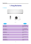
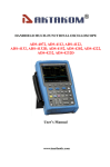
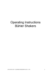
GE Consumer & Industrial Appliances Service Manual & Installation Manual Split System Air Conditioner Model numbers: GE AIR F24 GE AIR F34 GE AIR F41 -1- -2- -3- Introduction and Features Model Remarks GE AIR F24 1PH -4- 230V 50Hz R407C Model Remarks GE AIR F34 3PH -5- 400V 50Hz R407C Model Remarks 3PH GE AIR F41 -6- 400V 50Hz R407C GE AIR F24 Cooling Heating 1Ph 50Hz 230V 7000 8500 3000 3050 14.6 15.1 1170 2.3 2.3 2.79 GE AIR F24 IN 1360/1280/1240 100 Centrifugal Fan-4 ф125×134 Aluminum fin-copper tube ф7 3-1.6 1.042×0.19 MP35CA 4 PCB5A Transformer 0.2A ≤47 1300×188×600 1414×248×724 32/36 GE AIR F24 OUT 2900 2950 14.2 14.7 C-RN220H5B Rotary Type 75 Internal Inherent Protector Capillary Capacitor 7℃≤T≤43℃ Aluminum fin-copper tube ф9.52 2-1.8 725×813 Outdoor Unit Indoor unit Model Function Power (Phase-Frequency-Voltage) Total Capacity (W) Rated power (W) Rated current (A) Air flow volume (m3/h) Dehumidify volume (L/h) C.O.P/EER (W/W) Model Fan motor speed (r/min) (H/M/L) Output power of motor(W) Fan type-piece Diameter-length (mm) Evaporator Pipe diameter Row-fin distance (mm) Extended area of heat exchange (I×H×L) Swing motor model Power of motor (W) Fuse (A) Sound (pressure level) dB(A) Dimension (W/D/H) (mm) Dimension of package (W/D/H) (mm) Net weight/gross weight (kg) Model Input Power Running Current Compressor Model Compressor Type LRA(A) Compressor Overload Protector Type Throttle Method Starting Method Range of working temperature(℃) Condenser Pipe diameter Row-fin distance (mm) Extended area of heat exchange (I×H×L)mm Fan motor speed (rpm) Fan type-piece Fan Diameter (mm) Defrosting Method Sound (pressure level) dB(A) Dimension (W/D/H) (mm) Dimension of package (W/D/H) (mm) Net weight/gross weight (kg) Refrigerant/Refrigerant Charge (kg) Length Outer Liquid Pipe (mm) Diameter Gas Pipe (mm) Max. Height (m) Distance Length (m) Connecting Pipe 60/780 Axial Flow Fan-1 Ф450 Auto ≤58 950×412×840 1100×450×920 75/87 R407C/2.5 5 Ф9.52(3/8”) Ф 16(5/8”) 5 10 -7- Connecting Pipe Outdoor Unit Indoor unit Model Function Power (Phase-Frequency-Voltage) Total Capacity (W) Rated power (W) Rated current (A) Air flow volume (m3/h) Dehumidify volume (L/h) C.O.P/EER (W/W) Model Fan motor speed (r/min) (H/M/L) Output power of motor(W) Fan type-piece Diameter-length (mm) Evaporator Pipe diameter Row-fin distance (mm) Extended area of heat exchange (I×H×L) Swing motor model Power of motor (W) Fuse (A) Sound (pressure level) dB(A) Dimension (W/D/H) (mm) Dimension of package (W/D/H) (mm) Net weight/gross weight (kg) Model Compressor Model Input Power Running Current Compressor Type LRA(A) Compressor Overload Protector Type Throttle Method Starting Method Range of working temperature(℃) Condenser Pipe diameter Row-fin distance (mm) Working Area mm2 Fan motor speed (rpm) Fan type-piece Fan Diameter (mm) Defrosting Method Sound (pressure level) dB(A) Dimension (W/D/H) (mm) Dimension of package (W/D/H) (mm) Net weight/gross weight (kg) Refrigerant/Refrigerant Charge (kg) Length Outer Liquid Pipe (mm) Diameter Gas Pipe (mm) Max. Height (m) Distance Length (m) GE AIR F34 Cooling Heating 3Ph - 400V - 50Hz 10000 11500 4400 4400 7.5 7.5 2100 2.6 2.27 2.61 GE AIR F34 IN 1140/1070/980 150 Centrifugal Fan-4 ф145×175 Aluminum fin-copper tube ф7 3-1.6 1.34×0.25 GE AIR F41 Cooling Heating 3Ph - 400V - 50Hz 12000 13000 5000 4600 8.3 7.8 2200 3.4 2.4 2.83 GE AIR F41 IN 1110/1000/900 150 Centrifugal Fan-4 ф155×175 Aluminum fin-copper tube ф7 3-1.6 1.34×0.25 MP35CA 4 PCB5A Transformer 0.2A ≤52 1590×238×695 1770×330×830 42/53 GE AIR F34 OUT C-SBN303H8A 4250 4250 6.9 7 Rotary Type 42 Internal Inherent Protector Capillary Capacitor 2℃≤T≤43℃ Aluminum fin-copper tube ф9.52 2-1.4 813×930 920 Axial Flow Fan-1 Ф482 Auto ≤62 1040×410×840 1100×450×880 90/105 R407C/3.1 5 Ф12(1/2”) ф19(3/4”) 5 10 MP35CA 4 PCB5A Transformer 0.2A ≤55 1590×238×695 1714×330×830 42/51 GE AIR F41 OUT C-SBN353H8A 4850 4450 7.6 7.1 Rotary Type 55 Internal Inherent Protector Capillary Capacitor 2℃≤T≤43℃ Aluminum fin-copper tube ф9.52 2-1.8 725×1218 840 Axial Flow Fan-2 Ф450 Auto ≤63 1250×950×412 1295×1110×450 112/133 R407C/3.4 5 Ф12(1/2”) ф19(3/4”) 5 10 -8- Component Name Applicable to GE AIR F24/ GE AIR F34 Swing Assy. Indoor unit Air outlet Decorative panel Air inlet Water outlet Front grill Remote controller Outdoor Unit Air outlet Connecting pipe Air outlet grill Drainage pipe Air outlet -9- Applicable to GE AIR F41 Indoor unit Swing Assy. Air outlet Decorative panel Air inlet Water outlet Front grill Remote controller Outdoor Unit Air outlet grill Air outlet Connecting pipe Air outlet grill Air outlet Drainage pipe -10- Overall and Installing Dimension Overall and Installing Dimension of Indoor Unit Applicable to GE AIR F24 IN Overall dimension Installing dimension -11- Applicable to GE AIR F34 IN/ GE AIR F41 IN -12- Overall and Installing Dimension of Outdoor Unit Applicable to GE AIR F24 OUT/ GE AIR F34 OUT Unit: mm Bolt Nut Wrench -13- Applicable to GE AIR F41 OUT Unit: mm Bolt Nut Wrench -14- System Diagram System Diagram for Cooling-and-Heating Unit Capillary 4-way valve Evaporator Cooling Heating Condenser Gas-liquid separator Compressor Switch on the power to start the unit. Low-pressure refrigerant vapor from evaporator is absorbed into the compressor, where it is compressed into high-temp. and high-pressure gas. The gas refrigerant is then diverted to condenser, where it is liquidized after heat exchange with outdoor air. After that, the liquidized refrigerant flows through capillary for decrease of temperature and pressure and then enters into evaporator, where it becomes low-temp. and low-pressure refrigerant vapor after heat exchange with indoor air to be regulated. This process is repeated in cycle to achieve the purpose of cooling. (Under heating mode, the 4-way valve will change the flow of refrigerant, so that the condenser absorbs heats and the evaporator gives out heats, thus to achieve the purpose of heating). -15- 6 Electrical Diagram ○ GE AIR F24 GE AIR F34 -16- GE AIR F41 In case of any change in the Electrical Diagram shown above, please follow the drawing on cabinet. -17- Controller and Remote Controller Function Manual and Operating Instructions Controller and Remote Controller Function Manual 7.1.1 Temperature Parameters Indoor preset temperature (Tpreset) Indoor ambient temperature (Tamb.) Outdoor condenser temperature (Tcond.) 7.1.2 Basic Functions Once started under any mode, the compressor will not be stopped within 6 minutes with the change of ambient temperature. Once stopped, it cannot be restarted unless after 3-minute lag. 7.1.2.1 Cooling Mode When Tamb.≥Tpreset+1℃, the unit will run under cooling mode, in which case the compressor and outdoor fan will be started, the indoor fan will run at preset speed and the swing will run as preset. When T amb.≤Tpreset -1℃, the compressor and outdoor fan will be stopped and the indoor fan will run at preset speed. When Tpreset -1℃<T amb.< Tpreset +1℃, the unit will maintain its original operating status. Under cooling mode, the temperature can be set within a range from 16 to 30℃. The initial value is 25℃. Tamb Start cooling Tpreset Maintain original operating status Tpreset 6 min. 3 min. 6 min. Stop cooling Compressor Outdoor fan Indoor fan Run at preset speed Run Stop 7.1.2.2 Dehumidifying Mode When T amb.≥Tpreset +2℃, the unit will run under cooling mode, in which case the compressor and outdoor fan will be started, the indoor fan will run at low speed. When Tpreset -2℃≤T amb.≤Tpreset +2℃, the compressor, indoor unit and outdoor unit will run 6 minutes and stop 4 minutes in repeated cycle, while the indoor fan will run at low speed. When T amb.< Tpreset -2℃, the compressor and outdoor fan will be stopped, and the indoor ran will keep running at low speed. ¾ Under dehumidifying mode, the temperature can be set within a range from 16 to 30℃. The initial value is 25℃. Tamb Tpreset Start cooling Run under dehumidifying mode Tpreset 6 min. 4 min. 6 min. 4 min. Compressor Outdoor fan Indoor fan Low speed Run Stop -18- Stop cooling 7.1.2.3 Heating Mode When T amb.≤Tpreset -1℃, the unit will run under heating mode, in which case the 4-way valve, compressor and outdoor fan will be started, while the indoor fan will run at preset speed under preset cold air prevention condition. If T amb.≥Tpreset +1℃, the compressor and outdoor fan will be stopped, the 4-way valve is still energized and the indoor fan will run at low speed for 10 seconds before it is stopped. When Tpreset -1℃<T amb.< Tpreset +1℃, the unit will maintain its original operating status. ¾ Under heating mode, the temperature can be set within a range from 16 to 30℃. The initial value is 25℃. ¾ If the unit is switched off under heating mode or switched to another mode, the 4-way valve will be de-energized 2 minutes after the compressor is stopped. Start cooling Tpreset Ambient temperature Tamb Maintain original operating status Tpreset 6 min. 3 min. 6 min. Stop cooling Compressor Outdoor fan Indoor fan 5minutes ≤ Preset speed 5minutes ≤ Preset speed Louver valve Run Stop 7.1.2.3.1 Cold Air Prevention Condition The compressor will start at heat mode, indoor fan will not operate. After 5Min or if the outlet temperature is high, the indoor fan will run at preset speed. The indoor fan will no longer be stopped once it is started. Once running at preset speed, it will be impossible to change the speed of the indoor fan. 7.1.2.3.2 Defrosting Conditions When the condenser is detected to have frost, the system will enter into defrosting mode, in which case the 4-way valve, indoor fan and outdoor fan will be stopped. When it is detected that the frost in condenser is completely eliminated, the 4-way valve and outdoor fan will be started simultaneously, while the indoor fan will start to run under preset cold air prevention condition. ≤10 min. Compressor Outdoor fan ≤3min. Preset speed Indoor fan Run Stop 7.1.2.4 Fan Mode Indoor fan will run at preset speed Auto Speed Low Speed Medium Speed High Speed The temperature can be set within a range from 16 to 30℃. The initial value is 25℃. 7.1.2.5 Auto Mode Under this mode, the system will automatically select its run mode (cooling, dehumidifying, heating or fan) depending on ambient temperature. ¾ Once a mode is started, the unit will run at least 30 seconds before it can run the status of auto mode depending on ambient temperature. 7.1.3 AUTO ON/OFF and Sleep Function 7.1.3.1 Sleep If the controller is under cooling or dehumidifying mode, the preset temperature will be increased by 1℃ one hour after running under sleep mode and will be increased by another 1℃ after two hours. The temperature will increased by 2℃ within two hours. After that, the unit will run at this temperature. -19- Set the Temperature Tpreset Tpreset Tpreset Tpreset 1 hours 2 hours Over 2 hours If the controller is under heating mode, the preset temperature will be decreased by 1℃ one hour after running under sleep mode and will be decreased by another 1℃ after two hours. The temperature will decreased by 2℃ within two hours. After that, the unit will run at this temperature. 1 hours 2 hours Over 2 hours Tpreset Tpreset Set the Temperature Tpreset Tpreset No sleep function under fan mode or auto mode. 7.1.3.2 AUTO ON You can set AUTO ON function when the unit is under standby status. Upon the time of AUTO ON, the controller will run under preset mode. The time interval for AUTO ON is 0.5h, and can be set within 0.5 - 24 hours. 7.1.3.3 AUTO OFF You can set AUTO OFF function when the unit is under ON status. Upon the time of AUTO OFF< the system will be switched off. The time interval for AUTO OFF is 0.5h, and can be set within 0.5 - 24 hours. 7.1.4 Other Control 7.1.4.1 Swing Control You can switch on or off the swing by pressing the SWING key. The swing is valid only when the indoor fan is running. 7.1.4.2 Buzzer Control When the controller is energized or receives valid key-press signal, the buzzer will give a beep. 7.1.4.3 Automatic Control of Indoor Fan Speed Under this mode, the indoor fan will automatically select its speed, i.e. high, medium or low, depending on ambient temperature. Once a speed is activated, the indoor fan will run at least 30 seconds before it can switch over to other conditions. 7.1.5 Protection 7.1.5.1 Indoor Antifreeze Protection If E2 is displayed under cooling mode, the compressor, outdoor fan and indoor fan will be stopped, and the swing motor will maintain its original status. When evaporator temperature is higher than 6℃ and the compressor has been stopped for 4 minutes, the display will resume and the controller will run under preset mode. Under dehumidifying mode (i.e. run 6 minutes and stop 4 minutes), if it is detected within 3 minutes successively that the tube temperature is lower than -2℃ after the compressor has been running for 3 minutes, the compressor and outdoor unit will be stopped, the indoor fan will run at low speed, and E2 will be displayed. When tube temperature is higher than 6℃ and the compressor has been stopped for 4 minutes, the display will resume and the controller will run under preset mode. 7.1.5.2 Compressor High-pressure Protection If high-pressure protection is detected within 3 seconds successively, all loads will be closed, all key-press and remote control signals will be shielded, and E1 will be displayed. When it is detected within 6 seconds successively that the compressor has released high-pressure protection, shielding of key-press signal will be removed but E1 will be still displayed. To clear off E1 display, you have to press ON/OFF key to switch off the unit and press it again to restart. 7.1.5.3 Compressor Low-pressure Protection When it is detected that the low-pressure switch is off, the complete unit will be stopped and be automatically restarted after 3 minutes. If E3 is displayed, the unit cannot be restarted automatically, in which case you have to press ON/OFF key to switch off the unit and press this key again to restart. -20- If it is detected that the low-pressure switch is off when the compressor is stopped, the complete unit will be stopped, E3 will be displayed and the unit cannot be restarted automatically. You have to press ON/OFF key to switch off the unit and press this key again to restart. 7.1.5.4 Exhaust Pipe High-temp. Protection After the compressor is started, if the exhaust temperature is too high or exhaust sensor is in short circuit (or open circuit), the unit will be stopped when the indoor ambient temperature reaches the preset value. After the compressor is stopped for 3 minutes, the complete unit will be restarted when the exhaust temperature is resumed to normal. In case of above issue, the complete unit cannot resume its operation and E4 will be displayed. You have to press ON/OFF key to switch off the unit and press this key again to resume operation under preset mode. 7.1.5.5 Indoor Overtemperature Protection If it is detected that the evaporator tube temperature is too high under heating mode, the outdoor fan will be stopped. When the evaporator tube temperature resumes to normal, the outdoor fan will be started. 7.1.5.6 Low-voltage Protection If the current is detected over 22A as the compressor is started, the unit will be stopped when indoor ambient temperature reaches preset value. The compressor will automatically resume to its original operating status after it is stopped for 3 minutes. If E5 is displayed, the compressor cannot resume to its original operating status automatically, in which case you have to press ON/OFF key to switch off the unit and press this key again. 7.1.5.7 Fault Code and Definition Fault Code Definition E1 Compressor High-pressure Protection E2 Indoor Antifreeze Protection E3 Compressor Low-pressure Protection E4 Exhaust Pipe High-temp. Protection E5 Low-voltage Protection 7.1.5.8 Compulsory Cooling (Heating) Mode If no valid key-press upon first energization: ① From the remote controller, you can press temperature selection key (+) to enter into compulsory heating mode, in which case all the keys on front panel and remote controller will be shielded, all loads will be started and the indoor fan will run at high speed. If it is detected that ambient temperature is in open circuit or higher than 105℃, or that evaporator temperature is in open circuit or higher than 105℃, the buzzer will beep. After five minutes, the unit will be stopped and enter into normal standby status. ② From the remote controller, you can press temperature selection key (-) to enter into compulsory cooling mode, in which case all the keys on front panel and remote controller will be shielded, all loads except the 4-way valve will be started and the indoor fan will run at high speed. If it is detected that ambient temperature is in open circuit or higher than 105℃, or that evaporator temperature is in open circuit or higher than 105℃, the buzzer will beep. After five minutes, the unit will be stopped and enter into normal standby status. The functions stated in 1 and 2 are only for test purpose. Compulsory heating function is not available for cooling-only unit. 7.1.5.9 Indicator Power indicator: It is bright when energized and black when de-energized. It will blink under indoor antifreeze protection, compressor high-pressure protection, low-voltage protection and defrosting. Cooling indicator: It is bright under cooling mode, dehumidifying mode, auto cooling mode or auto dehumidifying mode. It is black under other modes. Heating indicator: It is bright under heating mode and auto heating mode. It is black under other modes 7.1.5.10 Power-OFF Memory Function Memory function includes the mode, swing, preset temperature, preset fan speed, Auto ON/OFF (If the power is cut off before the preset time for AUTO ON/OFF, the timer will count the time again once the power is resumed. If the power is cut off after the preset time for AUTO ON/OFF, the unit, once energized again, will run under the mode after preset AUTO OFF time). Once energized again after any de-energization, the unit can be automatically restarted according to the memory. -21- Description and Function of Remote Controller Keys Notes: z Make sure that there is no obstruction between remote controller and signal receiving window. z Do not fall off or throw the remote controller. z Do not let any liquid flow into remote controller, or expose the remote controller under direct sunshine or extreme hot temperature. FAN key Each press of this key will change the fan speed sequentially as below: SWING key One press of this key will enable the guide louver to swing at a specific angle. Another press will stop the guide louver. Auto Fan Note: The fan speed is not adjustable under Mode. TEMP. key Each press of (+) key will increase the preset temperature by 1℃. Each press of (-) key will decrease the preset temperature by 1℃. Under “ “ mode, the indoor temperature can be adjusted to any value between 16~30℃. Cooling mode Dehumidifying mode Fan mode Heating Mode ON/OFF key Press this key to start the air conditioner. Press it again to stop the air conditioner. MODE key The run mode will change sequentially as below with each press of MODE key. Auto -22- Description and Function of Remote Controller Keys (After opening the rear cover) Note: This remote controller is for general use and applicable to multiple types (functions) of air conditioner. AIR, HUMID, LIGHT, ANION and SAVE buttons are not used for these models. LCD display Display the information selected by each key SLEEP key Press this key to enter into sleep mode and press it again to exit sleep mode. Note: There is no sleep function under Auto or Fan mode. AUTO OFF key Pressing this key when the unit is running, you can set the AUTO OFF time from 0 to 24 hours. Cancel the AUTO ON/OFF Lamp indicator Press this key to switch on the lamp. Press it again to switch off the lamp. AUTO ON key Pressing this key when the unit is stopped, you can set the AUTO ON time from 0 to 24 hours. Each press of this key will increase the time by 0.5 hour. Cancel the AUTO ON/OFF -23- Installation of Remote Controller Batter z Operating Guideline General Procedures: 1. Switch on the power and press ON/OFF key to start the air conditioner. 2. Press MODE key to select your desired run mode. 3. Press SWING key to enable the guide louver to swing at a specific angle. Press it again to stop the swing. 4. Press FAN key to set the fan speed. 5. Press +/- key to set your desired temperature. Optional Procedures: 6. Press SLEEP key from remote controller to set the sleep mode. 7. Press AUTO ON/OFF key and then press +/- key to set the timer. Note: When auto mode is selected, the air conditioner will automatically select an appropriate run mode according to the indoor temperature, making the environment comfortable. z Replacement of Remote Controller Battery Two pieces of 7# alkali dry batteries are used in the remote controller. 1. Slide the battery cover of remote controller downward. Remove the old batteries and replace with two pieces of new batteries (Take care that the polarity shall be correct) 2. Close the battery cover of remote controller. Note: z Do not use new batteries together with old batteries, or use different types of batteries together. z To avoid leakage of liquid and damage to the remote controller, please take out the batteries if you will not use the remote controller in several weeks. z Operate the remote controller within effective range. z Keep the remote controller at least 1 meter away from television set or sound equipment. Battery cover RESET key Insert two 7# batteries. -24- Disassembly and Assembly Procedures Disassembly Procedures of Indoor Unit GE AIR F24 IN, F34 IN & F41 Disassemble Front Grill Sub-Assy Manually push the clasp of front grill sub-assy downward to open the front grill. (Fig 8-1) (Fig 8-1) Clasp Disassemble Left and Right Panels Use screwdriver to screw off the screws shown in the position, and then move the panels toward the direction of arrow to Disassemble the left and right decorative panels. (Fig 8-2) Screw (Fig 8-2) Disassemble Electric Box Assy A. Use screwdriver to twist off the two screws shown in the figure and remove the electric box cover (8-3); B. Use screwdriver to twist off the screw shown in the figure, remove the capacitor support, and disconnect the cables (refer to Figure 8-4); C. Use screwdriver to twist off the four screws (2 screws at each side), remove the electric box sub-assy, and disconnect the cables (refer to Figure 8-5); (Fig 8-4) -25- Screw (Fig 8-3) Screw Screw (Fig 8-5) Operating Procedures / Photos Disassemble Front Panel Assy Use screwdriver to screw off the six screws shown in the figure (two screws at the left, right and rear sides respectively), remove the front panel assy toward the direction shown in the figure to remove it (refer to figures 8-6, 8-7). Screw (Fig 8-6) Screw (Fig 8-7) Disassemble Guide Louver Sub-assy First remove the guide louver from the fitting position of the guide louver support, then remove the two ends of the guide louver from the fitting position of the swing motor. (Fig 8-8) Support Motor fitting position (Fig 8-8) Disassemble Water Tray Sub-assy Use screwdriver to screw off the three screws shown in the figure so as to remove the water tray sub-assy (refer to Figure 8-9). Screw (Fig 8-9) -26- Operating Procedures / Photos Disassemble Mounting Plate Sub-assy of Swing Louver Use screwdriver to screw off the screws at both ends of the mounting plate sub-assy of swing louver. Take the mounting plate sub-assy of swing louver apart from the guide louver support. (Fig 8-10) Screw Support (Fig 8-10) Disassemble Evaporator Assy Use screwdriver to screw off the screw shown in the figure. Remove the tube-exit clamp sub-assy of evaporator. (Fig 8-11) Use screwdriver to screw off the screw shown in the figure and remove the evaporator assy. Handle with care. (Fig 8-12、Fig 8-13) (Fig 8-11) Screw Screw Screw (Fig 8-13) Disassemble Air Outlet Rear Side Plate Sub-assy First remove the velvet sheet and the left and right side plate cushions at the air outlet; then use screwdriver to screw off the screw shown in the figure. (Fig 8-14) Screw (Fig 8-14) -27- (Fig 8-12) Operating Procedures / Photos Disassemble Mounting Plate Sub-assy of Swing Motor Use screwdriver to screw off the screw shown in the figure. (Fig 8-15) (Fig 8-15) Screw Disassemble Left and Right Side Plate Foam Sub-ass Follow the shown direction to remove the left and right side plate foam sub-assy. (Fig 8-16) Left Side Plate Foam Right Side Plate Foam Sub-assy Sub-assy (Fig 8-16) Disassemble Fan Motor Assy Press downward the clasps fitting the front and rear propeller housings, then pull upward to remove the front propeller housing (refer to Figure 8-17). Hold the clasp position of the rear propeller housing and pull upward to remove the rear propeller housing (refer to Figure 8-18). Use special tool to screw off the two holding screws at the coupling, move the coupling toward the fan until the coupling and shaft sub-assy can be removed; use special tool to remove the holding screw fixing the fan to remove the fan (refer to Figure 8-19). Clasp Position (Fig 8-17) Holding Screw (Fig 8-18) (Fig 8-19) -28- Operating Procedures / Photos Disassemble Bearing Mounting Plate Use screwdriver to screw off the four screws at the bearing mounting plate. (Fig 8-20) Screw (Fig 8-20) Disassemble Motor Use screwdriver to screw off the screw shown in the figure to remove the motor clamp and the motor fixing hoop. (Fig 8-20) Screw (Fig 8-20) Disassemble Motor Mounting Plate Sub-assy Use screwdriver to screw off the screw at the motor mounting plate to remove the motor mounting plate sub-assy. (refer to Figure 8-21). Motor Mounting Plate Sub-assy Screw (Fig 8-21) -29- Operating Procedures / Photos Disassemble Supporting Plate of Motor Support Use screwdriver to screw off the screws connecting the supporting plate of motor support and the rear side plate sub-assy with the motor support. (Fig 8-22) Tapping Screw (Fig 8-22) Disassemble Left and Right Mounting Plates Use tool to remove the bolts (2 X M8, 2 X M6) fixing the left and right mounting plates. (Fig. 8-23) Mounting Plate M8 Bolt (Fig 8-23) M6 Bolt Disassemble Motor Support Use screwdriver to screw off the screws at the rear support base plate and at the both sides of the support as shown in the figure to remove the motor support. (refer to Fig. 8-24、8-25). (Fig 8-24) Screw (Fig 8-25) -30- Disassembly Procedures of Indoor Unit Operating Procedures / Photos Applicable to the models: GE AIR F34 IN/ GE AIR F41 IN Disassemble Front Grill Sub-Assy Use tool to push the clasp 1 of front grill sub-assy downward to open the front grill. (Fig 8-26) Front Panel Clasp 1 (Fig 8-26) Disassemble Left and Right Decorative Panels Screw off the screw in the decorative panel, and then manually pull toward the direction of arrow to remove the left and right decorative panels. (Fig 8-27) Screw (Fig 8-27) Disassemble Electric Box Assy Use screwdriver to twist off the two screws at the electric box and manually pull the electric box cover upward to remove the electric box. (Fig 8-28) Use screw driver to loosen the two screws at upper and two screws at lower. Remove the capacitor board (As shown in Fig. 8-29) Use screwdriver to twist off the two upper screws and the two lower screws and remove the capacitor support. Use screwdriver to screw off the screw shown in Figure 5 and disconnect the cables to remove the electric box sub-assy. (Fig 8-30) Screw (Fig 8-28) Screw (Fig 8-29) Screw (Fig 8-30) -31- Operating Procedures / Photos Disassemble Front Panel Assy Front Panel Sub-assy Screw off the screws at the front and at the two sides. Remove the front panel sub-assy. (Fig 8-31) Screw (Fig 8-31) Disassemble Guide Louver Sub-assy First remove the guide louver from the fitting position of the guide louver support, then remove the two ends of the guide louver from the fitting position of the swing motor. (Fig 8-32) (Fig 8-32) Disassemble Water Tray Sub-assy Water Tray Use screwdriver to screw off the nut with washer at the middle of water tray. (Fig 8-33) Use screwdriver to screw off the two side screws of the auxiliary water tray. Pull the auxiliary water tray and the water tray upward to remove them. (Fig 8-34) Nut with Washer (Fig 8-33) Auxiliary Water Tray Screw Disassemble Mounting Plate Sub-assy of Swing Louver (Fig 8-34) Use screwdriver to screw off the screws at both ends of the mounting plate sub-assy of swing louver. Take the mounting plate sub-assy of swing louver apart from the guide louver support. (Fig 8-35) Screw (Fig 8-35) -32- Operating Procedures / Photos Disassemble Evaporator Assy Use screwdriver to screw off the two screws at the tube-exit plate of evaporator. Remove the tube-exit plate of evaporator. (Fig 8-36) Use screwdriver to screw off the screw shown in the figure to remove the evaporator. (Fig 8-37) Tapping Screw Tube-exit Plate of Evaporator ) Tapping Screw Disassemble Left and Right Mounting Plates (Fig 8-37) First remove the flocking fabrics and the left and right side plate cushions at the air outlet; then use screwdriver to screw off the screw shown in the figure. (Fig 8-38) Screw (Fig 8-38) Disassemble Mounting Plate Sub-assy of Swing Motor Use screwdriver to screw off the screw shown in the figure. (refer to Figure 8-39). Screw (Fig 8-39) -33- Operating Procedures / Photos Disassemble Mounting Plate Sub-assy of Swing Motor Use screwdriver to screw off the screw shown in the figure. (Fig 8-40) Left Side Plate Foam Sub-assy Right Side Plate Foam Sub-assy (Fig 8-40) Disassemble Fan Motor Assy Press downward the clasps fitting the front and rear propeller housings, then pull upward to remove the front propeller housing (refer to Figure 8-41). Hold the clasp position of the rear propeller housing and pull upward to remove the rear propeller housing (refer to Figure 8-42). Use special tool to screw off the two holding screws at the coupling, move the coupling toward the fan until the coupling and shaft sub-assy can be removed; use special tool to remove the holding screw fixing the fan to remove the fan (refer to Figure 8-43). (Fig 8-41) Clasp Position (Fig 8-42) Holding Screw Clasp Position Disassemble Bearing Mounting Plate Use screwdriver to screw off the four screws at the bearing mounting plate. (Figure 8-44). Disassemble Motor Use screwdriver to screw off the screw shown in the figure to remove the motor clamp and the motor fixing hoop.(Figure 8-45) Screw (Fig 8-44) -34- Screw (Fig 8-45) Operating Procedures / Photos Disassemble Motor Mounting Plate Sub-assy Motor Mounting Plate Sub-assy Use screwdriver to screw off the six screws at the motor mounting plate to remove the motor mounting plate sub-assy. (Fig 8-46) (Fig 8-46) Tapping Screw Disassemble Supporting Plate of Motor Support Use screwdriver to screw off the screws connecting the supporting plate of motor support and the rear side plate sub-assy with the motor support. (Fig 8-47) Tapping Screw (Fig 8-47) Disassemble Left and Right Mounting Plates Use tool to remove the bolts (2 X M8, 2 X M6) fixing the left and right mounting plates. (Fig 8-48) (Fig 8-48) Right Mounting Plate Left Mounting Plate Disassemble Motor Support Use screwdriver to screw off the screws at the rear support base plate and at the both sides of the support as shown in the figure to remove the motor support. Tapping Screw Bolt (Fig 8-49) -35- Bolt Disassembly Procedures of Outdoor Unit Operating Procedures / Applicable Models: GE AIR F24 OUT / GE AIR F34 OUT Disassemble Front Side Plate Screw off the four screws around the front side plate to remove the front side plate. (Fig 8-50) Front side plate Screw (Fig 8-50) Disassemble Top Cover Screw off the tapping screws around the top cover, and then pull the top cover upward to remove it. (Fig 8-51) Screw Top Cover (Fig 8-51) Disassemble Rear Grill Screw Screw off the four screws around the rear grill to remove the rear grill. (Fig 8-52) Rear Grill (Fig 8-52) -36- Operating Procedures / Photos Disassemble Housing Use screwdriver to screw off the screws around the cabinet to remove the housing. (8-53) Screw Housing (Fig 8-53) Screw Disassemble Electric Box Use screwdriver to screw off the screws fixing the electric box, and pull the electric box to remove it. (Fig 8-54) Electric Box Communication Ceiling Type Unit Electric Box Screw (Fig 8-54) Disassemble Right Side Plate Screw Use screwdriver to screw off the screws at the right side plat, condenser side plate, gas valve and liquid valve, and then pull the right side plate sub-assy upward to remove it. (Fig 8-55) Right Side Plate (Fig 8-55) -37- Operating Procedures / Photos Disassemble Axial Flow Fan Use spanner to remove the nut at the fan to remove the axial flow fan. (Fig 8-56) Nut Axial Flow Fan (Fig 8-56) Motor Disassemble Outdoor Motor Screw off the four tapping screws fixing the motor, pull out the motor lead-out cable plug, and remove the motor. Screw off the two tapping screws fixing the motor support, and pull the motor support upward to remove it. (Fig 8-57) Screw Fixing the Motor Motor Cable Motor Support Fixing Screw (Fig 8-57) Disassemble 4-Way Valve (Only Heating and Cooling Unit has such valve) Screw off the holding nut of the 4-way valve coil and remove the coil. Use wet cotton cloth to wrap the 4-way valve, unsold the four soldering points connecting the 4-way valve, and remove the 4-way valve. Be quick during the unsoldering process, pay attention to keep the wrapping cloth wet and do not allow the soldering flame to burn the compressor lead-out cable. (Fig 8-58) 4-Way Valve Soldering Point (Fig 8-58) -38- Operating Procedures / Photos Disassemble Capillary Unsold the soldering points at the capillary, the valve and the condenser to remove the capillary. Pay attention not to allow the soldering slag to block the capillary. (Fig 8-59) Capillary Disassemble Valve Unscrew the two screws fixing the gas valve, unsolder the soldering point between the gas valve and the return-air duct and remove the gas valve (note: when unsoldering the soldering point, use wet cloth to completely wrap the gas valve to prevent valve body from being harmed by high temperature). Unscrew the two screws fixing the liquid valve, unsolder the soldering point connecting the liquid valve and the fork type pipe, and remove the liquid valve. (Fig 8-60) Liquid Valve Disassemble Compressor Firstly unsolder the pipes connecting the compressor, and then unscrew the three foot nuts at the compressor to remove the compressor. (Fig 8-61) Foot Nut -39- Screw Gas Valve Disassembly Procedures of Outdoor Unit Operating Procedures/ / Applicable Models: GE AIR F41 OUT Disassemble Rear Grill Screw off the tapping screws at the rear side plate, valve support chassis and condenser side plate to remove the rear grill. (Fig 8-62) Rear Grill Screw Disassemble Top Cover Plate Screw off the tapping screws around the top cover, and then pull the top cover upward to remove it. (Fig 8-63) Screw Top Cover Disassemble Front Side Plate Screw off the three tapping screws at the front side plate, and then pull the front side plate upward to remove it. (Fig 8-64) Front Side Plate Screw -40- Operating Procedures / Photos Disassemble Housing Unscrew the screws around the housing to remove it. (Fig 8-65) Screw Housing Disassemble Electric Box Unscrew the screws around the electric box sub-assy to remove it. (Fig 8-66) Screw Communication Cassette Type Unit Electric Box Screw Disassemble Right Side Plate Unscrew the screws around the right side plate to remover the right side plate. (Fig 8-67) Right Side Plate Screw -41- Operating Procedures / Photos Disassemble Axial Flow Fan Use spanner to twist off the nut of the fan and remove the fan. (Fig 8-68) Nut Nut Disassemble Outdoor Motor Screw off the four tapping screws fixing the motor, pull out the motor lead-out cable plug, and remove the motor. Screw off the two tapping screws fixing the motor support, and pull the motor support upward to remove it. (Fig 8-69) Motor Screw Fixing the Motor Motor Support Fixing Screw Disassemble 4-Way Valve Screw off the holding nut of the 4-way valve coil and remove the coil. Use wet cotton cloth to wrap the 4-way valve, unsold the four soldering points connecting the 4-way valve, and remove the 4-way valve. Be quick during the unsoldering process, pay attention to keep the wrapping cloth wet and do not allow the soldering flame to burn the compressor lead-out cable. (Fig 8-70) 4-Way Valve -42- Operating Procedures / Photos Disassemble Valve Unscrew the screw fixing the valve, unsolder the connecting pipe of the valve, and remove the valve. (Fig 8-71) Screw Liquid Valve Screw Gas Valve Disassemble Capillary Unsolder the soldering points between the capillary and other pipes to remove the capillary. (Fig 8-72) Capillary Disassemble Compressor Unscrew the foot screw of the compressor and unsolder the connecting pipe to remover the compressor. (Fig 8-73) Foot Nut -43- 9 Care and Maintenance ○ Warning z Be sure to stop the unit and plug out the power before cleaning your air conditioner. Otherwise, electric shock may happen. z Never splash water on the indoor unit, this may cause the risk of electric shock. z Volatile liquids such as thinner or gasoline will cause damage to the appearance of air conditioner. (Only use soft dry cloth or wet cloth soaked with neutral detergent to clean the indoor unit). 9.1 To clean the filter Remove the filter and clean with vacuum cleaner. If very dirty, wash with warm water (below 45℃) that is added with neutral detergent. Fully dry the filter before reinstallation. Suggestion: Too dirty filter will reduce air inflow and result in system overload, causing 6% more consumption of power. Therefore, it is quite necessary to clean the filter regularly. 9.2 To clean the equipment and components Use dry and soft cloth or vacuum cleaner to clean the air conditioner and remote controller. If wet cloth is used, please wipe it dry after cleaning. Warning: Never expose the front grill or air filter directly under the sun. Never clean it with hot water over 45℃ or dry it on fire, (as this will cause decoloring, fire or deformation). 9.3 When using the air conditioner Check for any foreign articles that may obstruct the air into or out of the indoor and outdoor unit. If the unit is operating without air filter, dust will deposit and cause trouble to the unit. Generally, be sure to install filter before operating the unit. Check the drainage pipe for bend or damage. Check the equipment for normal and correct installation. 9.4 When the air conditioner is out of service Pull off the plug and disconnect the power. Clean the filter, equipment and components. Start the fan for 2 to 3 hours to clean and dry the inside of the equipment. -44- 10 ○ Trouble-Shooting When set short-circuiter as “ ON ” , it trips immediately Trip of circuit breaker or burn-out of fuse Air –conditioning unit cannot be started When turning the air-conditioning unit to the “ON”status, trip of circuit breaker occurs several minutes later When air-conditioning unit is powered on, there is no action (when the unit is plugged in, buzzer does not sound and there is no action after using the remote controller to start the unit) Remote controller does not receive signal (when unit is powered on, buzzer shall sound, unless buzzer is damaged) Failure of air-conditioning unit or component insulation failure, short circuit or electricle leakage owing to insulation puncture after heating, measure insulation resistance or check the components one by one to find the ones with failure; failure of circuit breaker itself, replace it. No power supply Power plug is not firmly seated or connection is poor Check and secure the plug to ensure firm contact Controller fuse burned out Replace controller fuse Connection line of transformer is loose or suffers from poor plugging, or there is transformer failure Secure line connections; measure output voltage of transformer and replace transformer if it is incorrect Controller is damaged Replace controller Batteries of remote controller are running out of power Replace battery Remote controller failure Receiving head is loose or plug connection is poor Receiving damaged Power voltage is too low Check insulation resistance for grounding; Confirm if air-conditioning unit has electrical leakage or is short-circuited head is First press “AUTO” key of manual switch. If there is no action check according to the above method; if the operation is normal after pressing the key, recheck to see if the mounting position of receiving head and the line connections are correct; if they are correct, replace receiving head or remote controller. Check power voltage. If the voltage is 10% than rated voltage, check the cause, and improve the power supply conditions such as adding regulated power supply. -45- Set temperature appropriate is Adjust the set temperature not Check if the cooling (heating) load is appropriate Check the forecasted cooling (heating) load Leakage of refrigerant or insufficient refrigerant Poor cooling (heating) effect Failure of refrigerant flow Leakage between internal high pressure and low pressure sections of compressor Replace compressor 4-way valve failure Replace 4-way valve Partial block in capillary Replace capillary Observe the condensation condition of evaporator or the reading of high pressure meter to judge if the system is blocked; deal with the system accordingly Block in cooling system Poor thermal insulation of connecting pipe between indoor unit and outdoor unit Insufficient air circulation volume The thermal insulation of big pipe and small pipe shall be separate and sound; joint and bare position of copper pipe shall also have thermal insulation Block in outdoor heat exchanger Wash away dust on surface of heat exchanger Block in air filter Clean filter Fan speed was set too low Set fan speed as high or medium Fan speed lower Capacitor is damaged Replace capcitor Motor is damaged Replace motor turns Mounting position of outdoor unit is inappropriate Outdoor temperature is too high Check leakage, carry out vacuum-pumping after repairing leakage and charge refrigerant according to requirements Outdoor unit shall be installed in a place with good ventilation Install proper weather screen; it is suggested to replace air-conditioner unit with one of higher capacity in case the best available cooling effect does not satisfy needs Indoor space is not sufficiently closed, or people enters or leave the room frequently, or there is heating equipment operating in the room -46- Keep the indoor space as closed as possible, do not use electrical appliance generating large amount of heat When air supply mode is selected, the fan does not operate When in cooling or heating mode, compressor operates but outdoor fan does not operate When in cooling or heating mode, outdoor fan operates but compressor does not operate Indoor fan motor burned out or there is wire breakage or failure of overheating protector Replace fan motor or components with failure The internal overheating protector frequently breaks as overheating is caused by abnormity of motor Replace fan motor Wrong line connection Correctly connect lines according to electrical diagram Open circuit or damage of fan capacitor Replace it withfan capacitor of the same model and spec Outdoor fan motor is damaged Replace fan motor Wrong line connection Correctly connect lines according to electrical diagram Outdoor fan capacitor is damaged Replace fan capacitor Compressor failure Replace Compressor Operating capacitor of compressor is damaged Replace capacitor Voltage is too low or too high It is suggested to equip voltage regulator Wrong line connection Correctly connect lines according to electrical diagram Failure of protector itself Compressor is overheated so protector is activated Use universal meter to check if contacts of compressure not overheated are conducting; replace protector in case of non-conducting conditions Insufficient or too much refrigerant Adjust refrigerant amount Capillary is blocked so air intake temperature is too high Replace capillary Compressor does not operate smoothly (seized or jammed), air discharge valve is damaged Replace Compressor Failure of protector itself Replace protector Torque of swing motor is insufficient Swing louver does not run Fisrtly check if line connections have fault, if no, replace components at failure position Wrong line connection Controller is damaged (IC2003 is damaged, swing relay cannot close -47- Abnormal sound and vibration Fan of indoor unit touches other positions Adjust fan position Foreign articles inside the indoor unit Remove foreign articles Vibration of compressor is violent Adjust support foot mat of compressor, tighten loose bolts Pipes of outdoor unit bump together Separate bumping pipes Metal plates bump together inside the unit 1. Tighten connection screws 2. Attach vibration damping gum between metal plates Indoor fan bumps cabinet Adjust fan position Abnormal sound compressor from inside Replace Compressor Abnormal electromagnetic noise from 4-way valve when in heating operation Internal short circuit of solenoid valve, replace solenoid valve Block or breakage of drainage pipe Replace drainage pipe The refrigerant pipe joint is not wrapped firmly Wrap and bind it again firmly Water leakage In case of the following protection or failures, the indoor unit shall display corresponding codes, which are explained as follows: Code Explanation E1 Compressor High-pressure Protection E2 Indoor Antifreeze Protection E3 Compressor Low-pressure Protection E4 Exhaust Pipe High-temp. Protection E5 Low-voltage Protection -48-