1
OPTICAL
MARK READER
SR-430
OPTICAL
MARK READER
SR-430
Operating manual
Operating manual
Head Office : 7-24-14, Oizumi-Gakuen-cho, Nerima-ku, Tokyo 178-8686, Japan
Telephone : (03)3978-2335 Fax : (03)3978-5229
C43497511-01
Introduction
Introduction
Thank you very much for purchasing our product.
Before using this product, be sure to thoroughly read this manual so that you can use it properly.
Notice
Microsoft Visual Basic is a registered trademark of Microsoft Corporation.
This product must not be reproduced or modified without permission from SEKONIC.
Before Usage
Before Usage
Make sure that the following are contained in the package immediately after unpacking the product.
1. Main unit
2. Power code
3. Operation manual
4. Stopper plate
5. Cards
1) 12-line standard-sized check cards
(5)
2) 15-line postcard-sized check cards
(5)
3) Paper feeding roller protection card
(1)
6. CD-ROM
Warranty
Warranty
This product will be warranted without any charge for one year after delivery.
In case of a failure occurring during this period, we repair it for free if it is judged to be related to our
responsibility. In this case, we temporarily keep the failed product to repair it. For details, contact the
shop at which you have purchased it.
In case that the free warranty period has expired or the failure is related to your responsibility or has
resulted from a worn part, we will repair it with charge.
The scope of this warranty is limited to this product and its accessories. Note that SEKONIC will not be
responsible for any financial damage, lost profit or claim from a third party resulting from operation of
this product.
Safety Precautions
Safety Precautions
This "Safety Precautions" page lists various symbols for ensuring safety operation of this product so as to
prevent users, other people or properties from being damaged.
Thoroughly read these precautions and understand the meanings of the symbols before proceeding to the
main text of this manual.
Warning
Improper operation by neglecting this instruction may result in death or serious
injury.
Caution
Improper operation by neglecting this instruction may result in personal or property
damage.
Neglecting this instruction may generate smoke or a fire.
Neglecting this instruction may cause an electric shock.
Indicates a prohibited action.
Indicates that disassembly or modification is prohibited.
Instructs that the power code must be removed from the outlet for safety operation.
Instructs that the part must be grounded for safety operation.
Warning
Warning
● A fire or an electric shock may result if this product continues to be used with
strange smell or sound.
In this case, immediately turn the power switch off and then remove the power
code from the outlet. After making sure that smoke generation has stopped,
ask the sales shop for repair.
Never attempt to repair by yourself since it may cause serious danger.
● Do not modify or disassemble this device. Otherwise, it may cause a fire or an
electric shock.
● Do not remove the cover from this device. Otherwise, it may cause an electric
shock. Ask the sales shop for internal check, adjustment or repair.
Pay enough attention to the above instructions. Otherwise, a fire or an electric
shock may occur.
● Precautions on device
•Do not use it with other supply voltage than the specified one.
•Do not install it in a place subject to liquid like water or oil, steam, moisture or
dust.
•Do not insert or drop any metal, foreign matter like combustibles, etc from the
port.
•Do not place a container with chemicals or water or a small metal piece near
the device.
● Do not cover the vent hole. Otherwise, heat is contained inside, resulting in a
fire.
● If the device should be dropped or the cover broken, immediately turn the power
switch off and remove the power code from the outlet. Then, contact the sales
shop.
● If a foreign matter should enter inside, immediately turn the power switch off
and remove the power code from the outlet. Then, contact the sales shop.
If the device continues to be used with a foreign matter inside, a fire or an
electric shock may occur.
If water or other foreign matter should enter inside, immediately turn the power
switch off and remove the power code from the outlet. Then, contact the sales
shop. If the device continues to be used with water or other foreign matter
inside, a fire or an electric shock may occur.
Caution
Caution
● Be sure to ground the main unit with a ground cable. Otherwise, an electric
shock may occur.
● When connecting or disconnecting the ground cable, be sure to remove the
power code from the outlet. Otherwise, an electric shock may occur.
● Do not place the device in an unstable location. Otherwise, it may fall, resulting
in an injury.
● When opening or closing the upper part of the main unit, do not place your hand
on the paper feeding surface. Otherwise, the finger may be caught, resulting in
an injury.
● When placing your hand on the paper feeding surface of the main unit, be
careful not to allow your finger to be caught or hit.
● When maintaining the device, be sure to remove the power code from the outlet
for your safety.
● When the device is not in use for long periods, remove the power code from the
outlet for safety.
● Before moving the device, be sure to remove the power code from the outlet.
If the cable is damaged, a fire or an electric shock may result.
● Do not connect or disconnect the power code or connection plug with a wet
hand.
Otherwise, a fire or an electric shock may result.
● Do not put a heavy substance on the device.
Otherwise, it may fall, resulting in an injury.
Table of Contents
Table of Contents
1. Precautions on Usage ......................................................................................................... 1
2. Names of Each Part ........................................................................................................... 2
3. Specifications ..................................................................................................................... 5
4. Installing the USB Driver .................................................................................................. 6
4-A Before installation ..................................................................................................... 6
4-B Installation Procedure ................................................................................................ 7
4-C Checking the Assigned port .................................................................................... 10
4-D Troubleshooting for Communication Errors ........................................................... 11
4-E Uninstall Procedure ................................................................................................. 12
5. Operation ......................................................................................................................... 13
5-A Preparation .............................................................................................................. 13
5-B Functions and Operating Method of Operation Panel ............................................. 14
5-C Setting Cards ........................................................................................................... 15
5-D Power Connection and Operation Test .................................................................... 19
5-E Test Mode ................................................................................................................ 19
5-F Troubleshooting ....................................................................................................... 20
6. Connection to Computer .................................................................................................. 22
7. How to Enter Mark .......................................................................................................... 23
8. Adjusting Reading Sensitivity ......................................................................................... 24
9. Control Commands .......................................................................................................... 27
9-A Initialize Commands ............................................................................................... 27
9-B Card Feed Commands ............................................................................................. 37
9-C Device Control Setting Commands ......................................................................... 38
10. Data Transfer Mode ......................................................................................................... 39
10-A Data Transfer Commands ..................................................................................... 39
10-B A Mode (1-byte Fixed Output Command) ........................................................... 40
10-C C Mode(Fixed Length Output Command) ........................................................... 41
10-D CA Mode(Fixed Length Output Command for Automatic Density Distinction) . 42
10-E E Mode(Variable Length Output Command) ....................................................... 43
10-F EA Mode(Variable Length Output Command for Automatic Density Distinction) ... 44
10-G ED Mode(Variable Length Output Command with Density Data) ...................... 45
10-H ES Mode(Variable Length Output Command by Density and Mark Data) ......... 46
10-I
G Mode(EBCDIC Code Convert and Output Command) ................................... 47
10-J
B Mode ................................................................................................................. 48
10-K D Mode ................................................................................................................. 48
10-L F Mode ................................................................................................................. 48
10-M Other Commands ................................................................................................. 49
10-N SR-305 Compatible Command ............................................................................ 52
11. Cleaning and Time of change of parts ............................................................................. 53
Table of Contents
12. External Views ................................................................................................................. 55
13. Appendix ......................................................................................................................... 56
13-A Reference for card creation .................................................................................. 56
13-B Code Tables .......................................................................................................... 62
13-C Typical sample program ....................................................................................... 64
13-D Check card ............................................................................................................ 67
1.Precautions on Usage
1. Precautions on Usage
Handle the device with the following in mind so as to enable the functions of it to be fully utilized.
(1) Before usage, make sure that the power connector is firmly connected to an outlet. Avoid connecting
or disconnecting the connector during operation or while the power switch is turned on.
(It may result in a failure.)
(2) Since the card reading part is equipped with an optical lens, never insert a screwdriver or the like.
(Otherwise, reading may be disabled.)
If card feeding is disabled due to clogged dust or the like in the card feeder, open the top cover to
remove it. (Refer to "11. Cleaning".)
(3) Allow an interval of at least 5 seconds between turning the power switch on and off.
(Otherwise, a failure may result.)
(4) Be sure to ground the device so as to prevent noise or static electricity from damaging the device.
Also, do not touch the metallic part of the device during card feeding operation.
If the device is used without being grounded or the metallic part is touched, malfunction or an electric shock may result.
(5) Do not place the device in a place subject to direct sunlight or near a heater. Also be careful not to
allow sudden temperature change, moisture, dust or excessive shock around the device.
(Otherwise, a failure like wrong paper feeding, reading or operation may occur.)
(6) When the device is not in use for long periods, insert the paper feeding roller protection card between
the paper feeding roller and the separation pad to prevent the roller material from deteriorating.
(7) If the paper feeding roller becomes soiled with powder from card paper or pencil, the roller and the
card may slip.
In order to prevent it, clean the paper feeding roller at proper intervals. (Refer to "11. Cleaning".)
(8) If the exterior of the device is soiled, slightly wipes with soft cloth wetted with water or neutral
detergent. Note that wiping with cloth wetted with volatile chemicals like benzine or thinner may
cause deforming or decoloring.
-1-
2.Names of Each Part
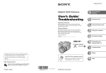
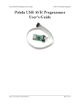
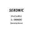
2. Names of Each Part
Clear switch
Feed switch
TEST LED (yellow)
ERROR LED (red)
Power switch
READY LED (green)
POWER LED (orange)
Fuse holder
Total counter
USB
Ground terminal (reserved)
RS-232C
Power connector
Power code
-2-
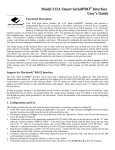
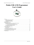
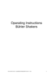
2.Names of Each Part
Side guard
Card stopper
Stacker
Lock lever
Top cover
Guide lock lever
Side guide
Guide wire
-3-
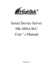
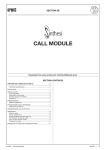
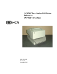
2.Names of Each Part
Rotary switch (SW2)
DIP switch (DIPSW)
Rotary switch (SW1)
Card detection sensor
Rotary switch (SW3)
Separation pad
Paper feeding roller
-4-
3.Specifications
3. Specifications
1.
Available cards
Card size: Standard-sized card, postcard-sized card, long-sized card
Paper type: OCR paper.
Paper ream weight: (70)* 90kg to 135kg
(basic weight: (83.8g/m2) 104.7g/m2 to 157.0g/m2)
(thickness: (0.11mm) 0.13mm to 0.19mm)
The 70kg paper is available to standard size only.
2.
Mark line number
Standard-sized card: Data = 12 lines, timing = 1 line
Postcard-sized card: Data = 15 lines, timing = 1 line
3.
Mark column
140 columns max. (specified by program)
4.
Reading method
Direct-under type, timing control type, mark-to-mark type
5.
Marking
Near-infrared light specifications: Pencil mark (HB), OCR marker
[infrared visible light specifications: The above + ball-point pen]
6.
Reading wavelength:
Near-infrared light specifications: 940nm
[infrared visible light specifications: 660nm]
7.
Card feeding rate
Approx. 256 sheets/min (AC 115V/50Hz, machine feeding rate using
standard-sized cards at room temperature)
8.
Hopper capacity
200 sheets max. (paper of ream weight of 110kg (basis weight of 127.9g/
m2), standard-sized card)
9.
Error check
Four types of errors can be judged (jam, timing mark, card empty and
double-feeding errors)
10. Self-check
The card detection sensor is to be checked.
11. Serial Interface
Serial EIA RS-232C-based, asynchronous, half-duplex,
data transfer rate = 2,400 to 38,400bps (variable)
variable data format
12. USB interface
USB 2.0 full-speed
Virtual COM Port Device
(same specification as 11.Serial interface)
13. Power supply
Supply voltage = AC 115V, Frequency = 60Hz
Current = Approx. 0.6A (during motor rotation)
Approx. 0.1A (in standby mode)
Supply voltage = AC 220V, Frequency = 50/60Hz
Current = Approx. 0.3A (during motor rotation)
Approx. 0.1A (in standby mode)
14. Operating environments Room temperature = 5 to 35C˚
Relative humidity = 40 to 80% RH (no dew condensation)
15. Overall dimensions
360 (L) x 222 (W) x 171 (H) (mm)
(Length in operation: 695 mm)
16. Weight
Main unit = Approx. 6kg
[ ] is option
-5-
4.Installing the USB Driver
4. Installing the USB Driver
The USB driver must be installed to use this product over a USB interface connection. If using this
product over a RS-232C connection, the driver does not need to be installed, and the procedures in this
chapter are not necessary.
4-A Before Installation
To use a USB interface connection, load the supplied CD-ROM, and install the driver by following
the installation procedure in this chapter.
Be sure to install the USB driver before inserting the SR-430 into the computer's USB port. The
driver cannot be installed properly if the SR-430 is inserted into the USB port first.
Notes
• If you accidentally connect the SR-430 before performing the installation, delete the falselyidentified driver from "Add or Remove Programs".
• To install the driver, you must log in as a user with administrator privileges.
Operating Environment
Software
USB driver
Windows2000 *1
OS
WindowsXP *2
WindowsVista *3
PC
Computer with USB interface in standard configuration *4
*1 Professional Edition SP4 or later
*2 Home/Professional Edition SP2 or later
*3 Home Basic/Home Premium/Business/Ultimate
*4 • The OS must be preinstalled.
• The software may not work for certain computer models and configurations.
• Operation is not guaranteed for systems with an upgraded OS, add-on USB interface, selfbuilt computers, built-to-order computers, and in emulator environments (such as VirtualPC).
• Operation is not guaranteed for connections that pass through a USB hub.
• A drive capable of reading CD-ROMs is required for installing the software.
-6-
4.Installing the USB Driver
4-B Installation Procedure (*The screens in the explanations below use Windows XP.)
(1) Check that the SR-430 is not connected.
(2) Start Windows, load the "driver CD", and run the installer program "sr430usbInstaller.exe" on
the CD.
Double click
(3) Click the "Install" button.
(4) Click "Continue Anyway". After installation is completed, the program will ask you to restart
the computer for certain environments. Click "Yes" to restart the computer.
-7-
4.Installing the USB Driver
(5) After the computer is restarted, turn on the power for the SR-430, and connect it to the computer's
USB port.
1) Turn on
the power
2) Connect to the PC
using a USB cable
(6) The Found New Hardware Wizard is started.
In response to "Can Windows connect to Windows Update to search for software", select "No,
not this time".
(7) In response to "What do you want the wizard to do", select "Install from a list or specific location (Advanced)".
-8-
4.Installing the USB Driver
(8) Select "Search for the best driver in these locations", insert a check mark for "Include this
location in the search", and click the Browse button and select the "C:\Program Files\SEKONIC
\SR-430" folder.
1) Select
2) Add check mark
3) Select the folder
(9) Click "Continue Anyway".
(10) Click "Finish" to complete the installation.
-9-
4.Installing the USB Driver
4-C Checking the Assigned Port
The COM port must be designated when using this software. After installing the USB driver, follow
the procedure below to check the port number assigned when using the USB interface.
(1) Right-click My Computer on the Desktop to open a pop-up menu, and click Properties.
(2) Select the "Hardware" tab, and click the Device Manager.
1) Select
2) Click
(3) Click Ports, and check the assigned port in parentheses for the "SR-430" entry.
-10-
4.Installing the USB Driver
4-D Troubleshooting for Communication Errors
-1 Changing the Assigned Port
The assigned port can be changed if the port number assigned to the SR-430 cannot be recognized by
the software or when you want to use a specific port. The procedure for changing the port is described below.
(1) Right-click the "SR-430" entry from the Device Manager screen (see section 4-C), and then
click Properties from the pop-up menu.
1) Right click
2) Click
(2) Select the "Port Settings" tab, and then click Advanced.
1) Select
2) Click
(3) At "COM Port Number", select the port number that you want to change to.
1) Select the port
-11-
4.Installing the USB Driver
4-E Uninstall Procedure
From the "Control Panel", go to "Add or Remove Programs", click the Change/Remove button, and
uninstall by following the instructions.
1) Click Change/Remove
2) Click Uninstall
-12-
5.Operation
5. Operation
5-A Preparation
Install the device and open the stacker. Set the card stopper at an appropriate position for the card
size to be used and raise the side guard at the specified position. (Make sure that the card stopper has
not been set inside out.)
During this operation, be careful not to allow bright light to directly enter the card ejector or hopper.
Open the stacker.
A
Raise the side guard.
Set the card stopper
like this.
B
C
Card stopper and card size
Position A: Long-sized card
Position B: Standard-sized card
Position C: Postcard-sized card
When using long-sized cards it is recommended to use the stopper plate so as to prevent paper from
coming out of the stacker.
Setting method: Engage the angled hole on the stopper plate with the protrusion at the center of the
top cover and firmly set it so that it is not disengaged even after you take off the hands.
(Be careful that the front and rear surfaces are set properly.)
Stopper plate
-13-
5.Operation
5-B Functions and Operating Method of Operation Panel
The operation panel is equipped with the following two switches and four LEDs (lamps):
(1) Functions of switches
FEED
: Pressing this switch feeds one card.
CLEAR
: Clears an error, if any.
The hardware or cover open error, however, cannot be cleared.
(2) Meanings of LED display
TEST (yellow)
: Comes on in the test mode.
ERROR (red)
: Comes on when an error occurs.
READY (green)
: Comes on when communication is enabled.
POWER (orange)
: Comes on when the power is turned on.
T
TES ROR
ER ADY
RE WER
PO
AR
CLE
FEED
Operation panel
-14-
5.Operation
5-C Setting Cards
(1) Pressing the [PUSH] button on the left of the hopper generates a "clicking" sound to lock the
hopper at the card setting position. Pressing the [PUSH] button again unlocks the hopper to
raise it. Do not unlock it by pressing the card.
(2) Set cards while the hopper is lowered at the setting position. Set them with the marked surfaces
facing upward and the timing mark sides facing left.
At this time, well-align the cards. Pay particular attention to the ends of the cards since a paper
feeding error may occur unless they are well-aligned.
(3) Press the side guide hard to the cards so that no clearance is allowed between them. Otherwise,
a reading error may occur.
When moving the side guide, keep pressing the guide lock lever (green). The side guide is fixed
when the lever is released.
(4) For the maximum card number settable onto the hopper, refer to the side guide index.
Note that setting too many cards on it may result in a paper feeding error or misreading.
(5) When using long-sized cards, raise the side guide toward the external side of the guide wire.
Pressing once: Locks the hopper.
twice: Unlocks the hopper.
How to move side guide
Slide it right and left while keep
pressing the guide lock lever (green).
Guide wire
Side guide index
-15-
5.Operation
Notes
1. Carefully handle cards so that they will not be bent or damaged. Otherwise, a paper
feeding or reading error may occur.
2. When adding cards, lower the hopper and be sure to reset cards. Otherwise, a paper
feeding error may occur.
(6) Setting double-feeding detection function
The device is equipped with a function to issue a double-feeding (DF) error.
A transmission-type sensor is used for detection and double-feeding is judged based on a difference in the amounts of light transmitted due to a difference in card thickness.
Before using the device, match the thickness of cards to be used and the paper ream weight
setting of SW3.
The settings of SW3 are as follows:
(If DF is detected in the SR-307 or SR-305 <SR-305S> mode, it is assumed to be a jam error,
outputting an error code.)
Position
1
2 3 4 5 6
*
DF sensitivity DF not judged Thin Thick
" * " refers to the initial setting.
Note
Please set position between 1and 6.
The deveice will not work correctly, In case of set other position from following.
Set position and paper ream weight (standard * )
Position
Paper ream weight (basis weight)
2
72kg (83.8g/m2)
3
90kg (104.7g/m2)
4
110kg (127.9g/m2)
5
135kg (157.0g/m2)
6
(160kg)
* Please set additional one step
more larger volume when DF
error occurred in a paper feeding.
Rotary switch (SW3): Sets paper ream weight.
SW1 SW2 DIPSW
SW3
Paper ream weight
Baud
rate
Density level
Setting
1~F
-16-
2
1 2 3 4 5 6 7 8
5.Operation
(7) Handling cards
1)
Do not use any card in one of the following states:
Soiled or damaged card, card to which dust or a foreign matter adheres, curled card or folded
card (folded in two, four, etc.)
2)
Storage of cards
Avoid storing cards in a place subject to sudden environmental change. Pay sufficient attention to moisture and keep them in a cabinet or the like. Do not leave them in a dusty place like
near a window.
3)
Before using new cards to test card feeding, be sure to loosen each card apart as shown in the
figure below so as to prevent double-feeding due to cards not completely separated.
-17-
5.Operation
OK
NG
Clearance
No clearance, but cards are not aligned.
-18-
5.Operation
5-D Power Connection and Operation Test
(1) Connect the power code after turning the power switch off.
(2) Turning the power switch on turns the "POWER" LED (orange) on to sound a buzzer.
This turns the device in the ready status for commands from the host computer.
If the "ERROR" LED (red) comes on or a buzzer continuously sounds, turn the power switch off
and refer to "5-F Troubleshooting".
(3) Pressing the "Feed" switch once feeds one card.
Keep pressing it continuously feeds cards.
5-E Test Mode
Test mode: Checks reading. For checking, use a specified check card.
(1) Turning the power switch on while pressing the "Feed" switch sounds a buzzer and calls the test
mode, turning all LEDs on.
(2) Pressing the "Feed" switch once continuously feeds cards. During this continuous feeding, a
buzzer goes off if a reading error occurs.
(3) Keep pressing the "Feed" switch stops card feeding.
(4) In order to exit from the test mode, turn the power off and on again.
Note
The check card to be used must be changed as follows depending on the setting of DIP
SW6:
DIP SW6 = OFF : Timing direct-under-type, 12-line, standard-sized card
ON : Timing control-type, 15-line, postcard-sized card
(With this setting, the mark-to-mark-type or direct-under-type selected by DIP
SW5 is neglected.)
-19-
5.Operation
5-F Troubleshooting
(1) Error display
Internal error
Hardware error (70H to 76H)
Card jamming
Card jam (31H or 32H)
- Card slips to prevent feeding.
- Card is attempted to be fed
Card feeding error (33H)
with the hopper being lowered.
Action
Turn the power off once and
on again. If the device is not
restored, contact the sales shop.
Remove cards by referring to
5-F-(2).
More than one card are fed at a
DF error (36H)
time.
Check the card conditions.
Timing mark read fails.
Timing mark error (40H)
Available timing marks are
three or less or no timing mark
is detected. Check cards.
Communication line error
between host computer and
device
- Overrun error
- Parity error
- Framing error
Communication error (51H)
Make sure that the
communication-related settings
are proper.
Invalid command or parameter
is entered.
Command or parameter error
(50H)
Enter a valid command or
parameter.
No card available in hopper.
Card empty (42H)
Set cards in the hopper.
Top cover is open.
Cover open (44H)
Close the top cover.
-20-
device.
Error type (HEX error code)
Reset the error by pressing the "Clear" switch to reboot the
Contents of error
5.Operation
(2) Action when a card jam or feeding error occurs
Follow the procedure below when a card jam or feeding error occurs.
Procedure
1)
Lower the hopper to open the top cover.
2)
Manually remove the jammed card(s).
3)
After removing, make sure that no torn piece of paper is left.
4)
Slowly lower the top cover toward you until it is locked.
(Make sure it is locked, otherwise, a feeding error may occur.)
This turns the "ERROR" LED (red) off.
5)
If the "ERROR" LED (red) is still on, repeat steps 3) and 4) again.
6)
Correct the error appropriately by referring to the following causes for a card jam or feeding
error.
Cause
Reference section for troubleshooting
Card deforming or breaking, foreign
1) and 2) in "(7) Handling cards" in 5-C.
matter adhered
Soiled roller
"(1) Cleaning of rollers"" in "11. Cleaning".
(3) Action when the device does not function
If the device should malfunction, correct it by referring to the following actions for each symptom.
Symptom
• The power cannot be turned on.
Action
Make sure that the power code is properly
connected.
• The "ERROR"LED (red) comes
Refer to 5-F-(1).
on after turning the power on.
• Reading is disabled.
• Make sure that the side guide is properly set. If
the clearance between the side guide and cards is
wide, cards are not fed properly, resulting in a
reading error.
• Aren't cards deformed?
• Aren't cards set in the opposite direction (leftside right, upside down, etc.)?
• Check operation of the device through self-check
using the attached check card.
• The program malfunctions.
• Make sure that the cable is not disconnected.
• Make sure that the communication-related
settings are proper.
-21-
6.Connection to Computer
6. Connection to Computer
SR-430 is available to connect either RS-232C or USB to the Computer.
The Computer is recognized USB interface, In case of both of cable connected to Computer.
Connection status
Only USB is connected.
USB
RS-232C
Available
N/A
N/A
Available
Available
N/A
Only RS-232C is connected.
USB & RS-232C are connected.
Connect the device to a computer by referring to the following procedure.
(1) Connection to Interface cable
This deveice is able to connect USB interface or RS-232C interface.
Please choose a cable which much as interface connector.
* RS-232C is needed to straight cable for connect between SR-430 and Computer.
Please set the following settings even if you use either USB initerface or RS232-C initerface.
(2) Setting data transfer rate
Set the same data transfer rate (baud rate) to this device and the computer. The device is set at
9,600bps by default. Before switching turning SW1, be sure to turn the power of the device off.
When setting the baud rate of the computer, refer to its operation manual.
The baud rate is set using 0 to 4 of SW1.
(* refers to the default setting)
Switch position
Baud rate
0
2,400
1
4,800
2
9,600
3
19,200
4
38,400 *
(5 to 9 are not used)
SW1: Sets baud rate.
SW1 SW2 DIPSW
SW3
Paper ream weight
Baud
rate
Density level
Setting
1~F
-22-
2
1 2 3 4 5 6 7 8
6.Connection to Computer
(3) Setting data format
Set the same data format to this device and the computer. The DIP switches are set as shown in the
table below by default. Before changing the settings of the DIP switches, be sure to turn the power of
the device off. When setting the data format of the computer, refer to its operation manual.
OFF
ON
1
2
3
4
5
6
#1 DIP switch function: Set the device as follows:
(* refers to the default settings)
DIP
SW No.
Meaning
ON
OFF
1
Sets Communication data
Data bit length = 8
format.
Data bit length = 7 *
2
Sets Communication data Parity check disabled
format.
*
Parity check enabled
3
Sets Communication data
Odd parity
format.
Even parity
4
Sets Communication data
Stop bit length = 1
format.
Stop bit length = 2 *
5
Read timing
Mark-to-mark type
Direct-under type
Changes line compatible
code in E mode
0123 ∼ : ; < = >
987∼XYABC
Lines to read
6
Card used in test mode
7,8
(note)
15
*
*
12
Postcard-sized, timing Card-sized, timing
control type
direct-under type
Operation mode
7
8
SR-430 *
(SR-410 compatible)
OFF
OFF
SR-307 compatible
ON
OFF
SR-305 compatible
SR-305S compatible
OFF
ON
Not used
ON
ON
*
Note:
Note that the reading sensitivity is graded in eight levels in the compatible mode.
-23-
7
8
6.Connection to Computer
(4) Communication control method
This device has the following two unreceivable states. In these states, set the communication timing
by the host computer.
1.
Due to half-duplex communication, data reception is disabled while the device is sending data.
2.
Data reception is disabled while the device is executing a command or the internal communication buffer is full.
The device notifies this state using an RS signal.
(5) Control line level
CS: The device sends data when this signal is at the high level.
RS: The device outputs low-level RSs in the unreceivable state.
DR: The device outputs high-level DRs while the power is turned on.
Signal level
High: +3V to +12V
Low: -3V to -12V
The following signals are only available to use RS-232C connection.
(6) Signal name and pin connection
External computer
This device
Signal
(GND)
(Data to send)
(Data to receive)
(Request to Send)
(Clear to Send)
(Data set Ready)
(Signal GND)
Signal direction
Signal
Pin
Pin
Signal
FG
SD
RD
RS
CS
DR
GND
1
2
3
4
5
6
7
1
2
3
4
5
6
7
FG
RD
SD
CS
RS
DR
GND
-24-
7. How to Enter Mark
7. How to Enter Mark
(1) Dimensions of mark
: Width = 3.5 to 5.0mm
Thickness = 0.4mm or moe
(2) Writing implements
: Pencil of HB or softer, OCR marker, mechanical pencil
(infrared visible light specifications: The above + ball-point pen)
(3) Density
: PCS = 0.7 min. (*1)
(4) Typical entries
OK
NG
(○)
(×)
Note:
When using a mechanical pencil, be sure to enter a mark with enough density.
(*1)
PCS = Printed Contrast Signal
It refers to the contrast in reflectance of a printed mark, symbol or letter against the non-printed
part of paper. It is calculated as follows:
PCS = (white reflectance - black reflectance)/white reflectance
-25-
8.Adjusting Reading Sensitivity
8. Adjusting Reading Sensitivity
Although the mark reading sensitivity of this device is set at level 4 by default, it can be changed so as not
to read stains as marks when particularly stained cards are read.
(1) Open the top cover of the device to turn SW2.
In SR-430 (SR-410 compatible) mode
Turn SW2 to level 1 to maximize the reading sensitivity.
Turn SW2 to level 0 to minimize the reading sensitivity.
IN SR-307/SR-305 (SR-305S) compatible mode
Turn SW2 to level 1 to maximize the reading sensitivity.
Turn SW2 to level 8 to minimize the reading sensitivity.
For SW2, use level 1 to 8 and do not use level 0, 9 to F.
(2) When adjusting the sensitivity, enter marks with different densities (line width or thickness) on mark
cards to test reading. Then, check and adjust entered marks and the reading sensitivity level using
SW2.
(3) Functions of SW2
SR-430 (SR-410 compatible) mode
SR-307/SR-305 compatible mode
Position
Sensitivity
1 2 3 4 5 6 7 8 9 A B C D E F 0
* High Reading sensitivity Low
Note
Position
Sensitivity
1 2 3 4 5 6 7 8 High Reading sensitivity Low
"*" refers to the default setting.
Reference detection density data of each level differs between the SR-430 (SR-410 compatible) and SR-307/SR-305 (SR-305S) compatible modes.
SW2: Adjusts sensitivity.
SW1 SW2 DIPSW
SW3
Paper ream weight
Baud
rate
Density level
Setting
1~F
2
1 2 3 4 5 6 7 8
-26-
9.Control Commands
9. Control Commands
This device operates according to command signals sent from the host computer. Control commands and
data are all sent and received in ASCII codes.
9-A Initialize Commands
The following commands are used to change the status of the device immediately after the power is
turned on:
-1
Kinds of Initialize Commands
Command
-2
Format
Explanation
DL
DLE DL∼
Sets the reading density.
DD
DC3 DD∼
Sets the difference in the reading
density.
T
DLE T∼
Sets the timing format.
DC3
DC3 ∼
DC3 L∼
Selects the 12-line or 15-line output.
Specifies the lines to be read in the
E, EA, ED or ES mode.
DC4
DC4 ∼
Sets separator codes and others.
CAN
CAN CR
Resets the device.
DLE DL Command (Reading Sensitivity Setting Command)
[Explanation]
This command is for setting the reading sensitivity level.
16 levels corresponding to density levels 1 to 16 can be set.
For example, a mark of density level 2 or more is read when "02" is set.
The setting of the rotary switch is enabled when the power is turned on while software is prioritized
when a DL command is used.
This setting is not stored after the power is turned off.
* This applies to when the CAN command is executed.
In the SR-307 compatible mode, the density levels are 1 to 8.
[Format]
DLE
D
(10H) (44H)
L
N1 N2
(4CH)
CR
(0DH)
N1N2: 2-byte ASCII code
-27-
9.Control Commands
-3
DC3 DD Command (Reading Density Difference Setting Command)
[Explanation]
This command is for setting the density difference allowable from the darkest mark in the CA and EA
modes.
After setting the difference, marks thinner than the setting are cancelled and those in the allowable
range are all output.
The density difference is set at "01" by default. In this case, mark data of the darkest density are
output.
This setting is not stored after the power is turned off.
* This applies to when the CAN command is executed.
Notes 1. Relationship with the sensitivity level setting
When there is one mark, the existence is judged according to the set sensitivity
level.
When there are more than one mark, the density differences are compared among
those at the set level or more and marks under the set level are cancelled.
2. When there are more than one mark at the same density level, more than one
pieces of data are also output.
e.g.1.
When the density level is set at 2 and there are marks of density 6, 4 and 3
If the density difference of 3 is specified, the mark under the density level of 3 (6 - 3
= 3) is cancelled and two pieces of data of density 6 and 4 are judged to exist and
output.
e.g.2.
When the density level is set at 4 and there are marks of density 8, 5, 4 and 3
If the density difference of 3 is specified, the mark under the density level of 4,
namely, the mark of density 3, is first cancelled due to the sensitivity level setting
and then the marks under the density level of 5 (8 - 3 = 5) are cancelled. Thus, data
of density 8 is judged to exist and output.
[Format]
DC3
D
(13H) (44H)
D
N1 N2
(44H)
CR
(0DH)
N1N2: 2-byte ASCII code
-28-
9.Control Commands
-4
DLE T Command (Timing Format Setting Command)
[Explanation]
This command is for setting mark read timing (timing mark type). If the DIP switch setting has not
been changed, the setting by this command is not required when the power is turned on.
When the T command is executed, the set value remains unchanged unless the device is reset or the
power is turned off.
When using the timing control type, be sure to set the read timing by this command.
-4-1 In SR-430 (SR-410 compatible) mode
[Format]
Host Computer
This device
DLE
T
CR
STX
(10H)
(55H)
(0DH)
(02H)
N
CR
Receive
(0DH)
* N: Specifies the format (1-byte ASCII numerical code between 1 and 5)
N
Mark read timing format
1
Timing control type
2
Direct-under type
3
Not used
4
Mark-to-mark type
(end or blank space not to be read)
5
Mark-to-mark type
(end or blank space to be read)
N values determine the mark read areas in the formats shown in the table below:
Setting method of timing control type
Specifying the timing control type with N = 1 when specifying the T command sets the read area at
three times of the timing mark.
[Format]
DLE
T
(10H) (55H)
CR
STX
1
(0DH) (02H) (31H)
CR
(0DH)
-29-
9.Control Commands
Descriptions of each read timing format ("R" refers to the read area)
[Descriptions of each control type]
R
d
1. Timing control type
R=dxm
m = Specified multiple (fixed at 3)
d = Timing mark width
R
2. Direct-under type
3. Mark-to-mark type
4. Mark-to-mark type
(front end or blank space not to be read)
(front end or blank space to be read)
-30-
R
1st column
1st column
R
R
Approx. 2.5mm
2nd column
9.Control Commands
-4-2 In SR-307 compatible mode
[Format]
Host Computer
This device
DLE
T
CR
(10H)
(55H)
(0DH)
N
CR
Receive
(0DH)
* N is the 1-byte ASCII numerical code indicating the reading method.
N values determine the mark read areas in the formats shown in the table below:
N
Mark read timing format
0
Mark-to-mark type
1
Timing mark direct-under type
2
Timing control type
(read multiple = 3 times)
-4-3 In SR-305 (SR-305S) compatible mode
[Format]
Host Computer
This device
DLE
T
CR
(10H)
(55H)
(0DH)
N
CR
(0DH)
* Specifies the timing control type.
N is the 1-byte ASCII numerical code indicating the reading method.
-31-
Receive
9.Control Commands
Descriptions of each read timing format ("R" refers to the read area)
[Descriptions of each control type]
R
d
1. Timing control type
R=dxm
m = Specified multiple (fixed at 3)
d = Timing mark width
R
2. Direct-under type
3. Mark-to-mark type
(front end or blank space to be read)
R
1st column
R
Approx. 2.5mm
2nd column
-32-
9.Control Commands
-5
DC3 Command (Read Line Specify Command)
[Explanation]
This command is for specifying the number of lines of data to be read. When the DC3 command is
executed, the set value remains until the device is reset or the power is turned off.
When the power is turned on or the device is reset, the number of lines will become the value set to
the DIP switch, and when the DC3 command is executed, the priority will be given to the software.
[Format]
DC3
N1 N2
(13H)
CR
(0DH)
The value of N1N2 determines the number of lines of data to be read.
N1N2 = 12 : Data is read assuming the number of lines as 12.
N1N2 = 15 : Data is read assuming the number of lines as 15.
(The modes in which the 15-line format is available are C, CA, D, E, EA, ED, ES and F modes.)
-6
DC3 L Command (Read Line Area Setting Command)
[Explanation]
This command is executed together with any of data read commands such as E, EA, ED and ES. This
command is for specifying the read area of each line and the range of line whose density is compared.
The setting of this command is not stored.
The initial value after the power is turned on is set for each column (as 12 lines or 15 lines).
Note :
When executed together with any of the E, EA, ED or ES command,
this command can specify square areas.
[Format]
DC3
L
N1 N2
M1 M2
(13H) (4CH)
CR
(0DH)
The values of N1N2 and M1M2 determine the range of lines to be read.
N1N2 : Read starting line counted from the timing mark side.
M1M2 : Number of lines to be read.
Note:
Although the E, EA, ED or ES command also follows the DC3 command, it does not follow
the DC3 command once the DC3 L command is used.
-33-
9.Control Commands
-7
DC4 Command (STX, ETX Setting Command)
[Explanation]
This command is for determining the ETX code following data output from the device and the recognizing method of received data.
When the DC4 command is executed, the set value remains until the device is reset or the power is
turned off.
[Format]
DC4
S1
S2
(14H)
S3
CR
(0DH)
The values of S1 determine the statuses of the ETX code, etc.
S1 = 0
: Initializes the device. (This value erases S1 = 7 data stored in the memory.)
Does not add the ETX (CR) code. (S2 and S3 are not necessary.)
S1 = 1
: Adds CR as the ETX (CR) code. (S2 and S3 are not necessary.)
S1 = 2
: Adds the code specified by S2 as the ETX code. (S3 is not necessary.)
S1 = 3
: Adds the STX code. This value adds the code specified by S2 as the STX code.
CR is added as ETX. (S3 is not necessary.)
S1 = 4
: Adds the STX and ETX codes. This value adds the code specified by S2 as the ETX code
S1 = 5
: The device neglects the codes specified by S2 or S3 as data at the time of reception (S3
and the code specified by S3 as the STX code.
can be omitted.)
Codes which are used in commands are not neglected.
Codes up to 6 bytes can repeatedly be specified (2-byte codes only in the 307 compatible
mode) .
All settable character codes are shown on the next page. All other codes cause command
errors.
S1 = 6
: Not used.
S1 = 7
: Stores the set STX and ETX codes. The set values remain even after the power is turned
on or the CAN command is executed. (S2 and S3 are not necessary.)
Note :
Only S1=0, 1, 2 and 5 are effective in the SR-307 mode.
-34-
9.Control Commands
Contents of separators added for each mode
- SR-430 (SR-410 compatible) mode
→ Command
↓
S1
0
1
2
3
4
0
1
2
3
4
?
∼
∼CR
∼ETX
STX∼CR
STX∼ETX
ENQ
∼
∼CR
∼ETX
STX∼CR
STX∼ETX
ENQ T
∼
∼CR
∼ETX
STX∼CR
STX∼ETX
ED
ES
∼CR
∼CR CR
∼CR CR
∼CR∼CR CR
∼CR ETX
∼CR∼CR ETX
STX∼CR CR STX∼CR∼CR CR
STX∼CR ETX STX∼CR∼CR ETX
C
∼
∼CR
∼ETX
STX∼CR
STX∼ETX
CAN
ACK
ACK
ACK
ACK
ACK
E
EA
∼CR
∼CR
∼CR CR
∼CR CR
∼CR ETX
∼CR ETX
STX∼CR CR STX∼CR CR
STX∼CR ETX STX∼CR ETX
" ∼ ": Data output from the device
- SR-307 compatible mode
0
1
2
3
4
?
∼
∼CR
∼ETX
STX∼CR
STX∼ETX
ENQ
∼
∼CR
∼ETX
STX∼CR
STX∼ETX
ENQ T
∼
∼CR
∼ETX
STX∼CR
STX∼ETX
ENQ S
∼
∼CR
∼ETX
STX∼CR
STX∼ETX
A
∼
∼CR
∼ETX
STX∼CR
STX∼ETX
B
∼
∼CR
∼ETX
STX∼CR
STX∼ETX
0
1
2
3
4
C
∼
∼CR
∼ETX
STX∼CR
STX∼ETX
CA
∼
∼CR
∼ETX
STX∼CR
STX∼ETX
D
∼
∼CR
∼ETX
STX∼CR
STX∼ETX
E
∼CR
∼CR
∼ETX
STX∼CR
STX∼ETX
EA
∼CR
∼CR
∼ETX
STX∼CR
STX∼ETX
ED
∼CR
∼CR
∼ETX
STX∼CR
STX∼ETX
0
1
2
3
4
ES
∼CR∼CR
∼CR∼CR
∼ETX∼ETX
STX∼CR∼CR
STX∼ETX∼ETX
0
1
2
3
4
K
∼
∼CR
∼ETX
STX∼CR
STX∼ETX
F
∼
∼CR
∼ETX
STX∼CR
STX∼ETX
L
∼
∼CR
∼ETX
STX∼CR
STX∼ETX
G
∼
∼CR
∼ETX
STX∼CR
STX∼ETX
CAN
ACK
ACK
ACK
ACK
ACK
-35-
H
∼
∼CR
∼ETX
STX∼CR
STX∼ETX
I
∼
∼CR
∼ETX
STX∼CR
STX∼ETX
J
∼
∼CR
∼ETX
STX∼CR
STX∼ETX
9.Control Commands
Character codes settable when S1 = 5
Upper 4 bit
Lower 4 bit
0
2
3
0
1
4
5
@
SH
2
!
D2
3
EX
4
ET
5
”
$
NK
%
6
AK
SN
&
7
BL
EB
’
8
BS
9
HT
EM
A
LF
SB
:
B
HM
EC
;
[
C
CL
→
<
¥
=
]
>
^
D
-8
1
(
)
,
←
E
SO
↑
F
SI
↓
.
_
CAN Command (Reset Command)
[Explanation]
This command is used as the reset command. (This command initializes the device.) After this
command is executed, the device is reset internally and returns the ACK code (06H). At the time, the
"READY" LED (green) and "ERROR" LED (red) blink. The host computer must be designed to
transmit the next command after receiving this code.
Separators like STX and ETX can be added by the DC4 command (only in the SR-430 (SR-410
compatible) mode).
[Format]
Host Computer
This device
CAN
Receive
CR
(18H) (0DH)
Reply
ACK
(06H)
-36-
9.Control Commands
9-B Card Feed Commands
-1 ? Command (Card Feed Command)
[Explanation]
When this command is transmitted, the device sends one card only and reads it. After reading the
card, the device outputs an error status code and waits for a command from the host computer.
Separators like STX and ETX can be added using the DC4 command.
[Format]
Host Computer
?
This device
CR
Receive
(3FH) (0DH)
Receive
Error status output
E
E: 1-byte error status (for the meaning, refer to the error status code table)
-2
Error Status Code Table
-2-1 SR-430 (SR-410 compatible) mode
Code
HEX
0
30H
Normal
Explanation
1
31H
Internal jam error (during card feeding)
2
32H
Cards remain inside the device.
3
33H
Card feed error (S2 cannot be turned on)
4
34H
Not used.
5
35H
6
36H
@
40H
A
41H
Not used.
DF error (only when a DF check is set)
(Double-feeding has occurred.)
Timing mark error
(only 3 or less timing marks detected)
Not used.
B
42H
Card empty
C
43H
Not used.
D
44H
Cover open
P
50H
An invalid command or parameter has been input.
Q
51H
Communication error
p
70H
q
71H
s
73H
t
74H
u
75H
v
76H
Hardware error of the main unit
* If a hardware error should occur, turn the power off once
and reboot the device.
If the device is not restored, contact the sales shop.
-37-
9.Control Commands
-2-2 SR-307 compatible mode
Code
HEX
0
30H
Cards have been sent normally.
Explanation
1
31H
Not used.
2
32H
Jam error (cards have not been sent normally.)
3
33H
4
34H
5
35H
Not used.
Timing mark error
(only 3 or less timing marks detected.)
Card empty
(There is no card in the card hopper.)
A jam error (32H) is assumed for the DF error.
9-C Device Control Setting Commands
-1 DC3 B Command (Buzzer Control Command)
[Explanation]
This command is for setting whether to sound a buzzer when no card exists or an error occurs.
The initial value after the power is turned on is set to flash the red LED three times and then turn the
light off without sounding a buzzer when no card exists (N = 0).
[Format]
Host Computer
DC3
B
N
(13H) (42H)
CR
(0DH)
The value of N determines the setting.
N = 0: The red LED flashes three times without sounding a buzzer when no card exists.
N = 1: The red LED does not come on but a buzzer goes off when no card exists.
N = 2: The red LED flashes three times without sounding a buzzer for all types of errors.
When no card exists
N=0
N=1
N=2
Buzzer
Not goes off.
Goes off.
Not goes off.
LED
Comes off after
flashing 3 times.
Not comes on.
Comes off after
flashing 3 times.
N=0
N=1
N=2
Buzzer
Goes off.
Goes off.
Not goes off.
LED
Comes on.
Comes on.
Flashes 3 times.
When an error occurs
-38-
10.Data Transfer Mode
10. Data Transfer Mode
10-A
Data Transfer Commands
The following commands are used to transfer data read from one card to the host computer:
-1 Types of data transfer commands
Mode
Explanation
A
Outputs the number at a mark when the mark is detected on the 9 to 0
lines in one column, or outputs a space when no mark or more than 2
marks are detected. The data is output as an ASCII code. The X and
Y lines are neglected.
B
Outputs data in one specified column in the A mode format.
C
Divides one column in units of 4 lines and outputs the ASCII codes of
0 to F regarding the data as hexadecimal numbers.
CA * Outputs the darkest mark in the C mode only as data.
D
Outputs data of one specified column in the C mode format.
E
Outputs ASCII codes corresponding to marked line positions.
EA * Outputs the darkest mark in the E mode only as data.
ED * Adds 1-byte density data after mark data in the E mode.
ES * Outputs mark and density data separately in the ED mode.
F
Outputs data of one specified column in the E mode format.
G
Reads EBCDIC-based punched-hole codes of one column and converts
the codes into ASCII codes to output them.
H
Outputs data of one specified column in the G mode format.
Modes marked "*" are for density-related commands.
Note:
The A, B, CA, D, F, G and H modes are available in the 307 compatible mode only.
-39-
10.Data Transfer Mode
10-B
A Mode(1-byte Fixed Output Command)
[Explanation]
This command is for outputting the number at a mark when a mark is detected on the 9 to 0 lines in
one column or outputs a space when no mark or more than two marks are detected. This device
neglects marks and prints on the X and Y lines and outputs data as a 1-byte fixed length ASCII code
for one column.
Separators like STX and ETX can be added using the DC4 command.
Note:
This mode is enabled only with the 12-line format setting.
Example
ASCII output data for the following marks
Y
X
0
1
2
3
4
5
6
7
8
9
YYYYY
XXXXX
0 0 0 0 0
1 1 1 1 1
2 2 2 2 2
3 3 3 3 3
4 4 4 4 4
5 5 5 5 5
6 6 6 6 6
7 7 7 7 7
8 8 8 8 8
9 9 9 9 9
1st column 2nd column 3rd column
Output data
4th column
ASCII code
0
1
SP
2
HEX code
30H
31H
20H
32H
[Format]
Host Compute
DLE
A
This device
N1 N2 N3 M1 M2 M3
(10H) (41H)
CR
Receive
(0DH)
Receive
Data output
###・・・・・#####
Fixed length of 1 byte a column x M1M2M3 columns
N1N2N3 : 3-byte ASCII code indicating read start column number
(Example) From the 3rd column = 003 (30H, 30H, 33H)
M1M2M3 : 3-byte ASCII code indicating number of columns to be read
(Example) 50 columns = 050 (30H, 35H, 30H)
Note:
N1N2N3 and M1M2M3 cannot be omitted as 6-byte fixed length data.
-40-
10.Data Transfer Mode
10-C
C Mode (Fixed Length Output Command)
[Explanation]
One column is divided in units of four lines. Existence of a mark on each line is indicated by "1" and
non-existence is indicated by "0." The 4-bit unit is regarded as a 4-digit hexadecimal number, and
the ASCII codes from 0 to F are output.
Data are of fixed length of 3 bytes a column.
(A 15-line postcard-sized card is a fixed length of 4 bytes a column. The 16th line, however, is
always "0" as a dummy line.)
Separators like STX and ETX can be added using the DC4 command.
Example
ASCII output data for the following marks in one column
Y
X
0
1
2
3
4
5
6
7
8
9
YYYYY
XXXXX
0 0 0 0 0
1 1 1 1 1
2 2 2 2 2
3 3 3 3 3
4 4 4 4 4
5 5 5 5 5
6 6 6 6 6
7 7 7 7 7
8 8 8 8 8
9 9 9 9 9
Output data
Number of lines
1 2 3 4 5 6 7 8 9 10 11 12
One column
0 0 0 0 0 0 0 1 0 0 1 0
ASCII code
0
1
2
HEX code
30H
31H
32H
[Format]
Host Computer
DLE
C
This device
N1 N2 N3 M1 M2 M3
(10H) (43H)
CR
Receive
(0DH)
Receive
Data output
###・・・・・#####
Fixed length of 3 (4) bytes a column x M1M2M3 columns
N1N2N3 : 3-byte ASCII code indicating read start column number
(Example) From the 3rd column = 003 (30H, 30H, 33H)
M1M2M3 : 3-byte ASCII code indicating number of columns to be read
(Example) 50 columns = 050 (30H, 35H, 30H)
Note :
N1N2N3 and M1M2M3 cannot be omitted as 6-byte fixed length data.
-41-
10.Data Transfer Mode
10-D
CA Mode (Fixed Length Output Command for Automatic Density Distinction)
[Explanation]
The data format is the same as the one in the C mode.
This command is for automatically distinguishing mark density for one column. When there are
several marks, it cancels light-colored marks of larger density difference than the set difference and
outputs marks of smaller density difference than the set difference. Since the density difference is set
at 01 by default, the darkest mark data is output in this case. Density difference between a dark mark
and the next darker mark to be canceled can be set using the DC3 DD command.
Separators like STX and ETX can be added using the DC4 command.
Note: Relationship with sensitivity level setting
When there is only one mark, the existence of a mark is distinguished according to the preset sensitivity level.
When there are several marks, density differences are compared among marks of density more than
the preset sensitivity level.
Marks of density less than the preset sensitivity level are canceled.
Note:
When there are several marks of the same density level, data is also output in a plural form.
[Format]
Host Computer
DLE
C
This device
A N1 N2 N3 M1 M2 M3 CR
(10H) (43H) (41H)
Receive
(0DH)
Receive
Data output
###・・・・・#####
Fixed length of 3 (4) bytes a column x M1M2M3 columns
N1N2N3 : 3-byte ASCII code indicating read start column number
(Example) From the 3rd column = 003 (30H, 30H, 33H)
M1M2M3 : 3-byte ASCII code indicating number of columns to be read
(Example) 50 columns = 050 (30H, 35H, 30H)
Note:
N1N2N3 and M1M2M3 cannot be omitted as 6-byte fixed length data.
-42-
10.Data Transfer Mode
10-E
E Mode (Variable Length Output Command)
[Explanation]
This command is for returning ASCII codes corresponding to marked line positions. Data are of a
variable length corresponding to the number of marks. CR codes are added at break points between
columns.
When no mark is detected in a column, "a space + CR" is output.
The correspondence between line positions and ASCII codes can be set in two ways as shown in the
tables below by turning DIP SW6 on and off.
Separators like STX and ETX can be added using the DC4 command.
DIP SW6 = OFF
Line
1
2
3
4
5
6
7
8
9
10
11
12
13
14
15
Code
9
8
7
6
5
4
3
2
1
0
X
Y
A
B
C
DIP SW6 = ON
Line
1
2
3
4
5
6
7
8
9
10
11
12
13
14
15
Code
0
1
2
3
4
5
6
7
8
9
:
;
<
=
>
[Format]
Host Computer
DLE
E
This device
N1 N2 N3 M1 M2 M3
(10H) (45H)
CR
Receive
(0DH)
Receive
Data output
# CR # CR・ ・ ・ # CR # CR
Data of X+1 bytes a column x M1M2M3 columns
X + 1: Variable length data of number of marks + 1-byte "CR"
N1N2N3 : 3-byte ASCII code indicating read start column number.
(Example) From the 3rd column = 003 (30H, 30H, 33H)
M1M2M3 : 3-byte ASCII code indicating number of columns to be read.
(Example) 50 columns = 050 (30H, 35H, 30H)
Note:
N1N2N3 and M1M2M3 cannot be omitted as 6-byte fixed length data.
-43-
10.Data Transfer Mode
10-F
EA Mode (Variable Length Output Command for Automatic Density Distinction)
[Explanation]
The data format is the same as the one in the E mode.
This command is for automatically distinguishing mark density for one column. When there are
several marks, it cancels light-colored marks of larger density difference than the set difference and
outputs marks of smaller density difference than the set difference. Since the density difference is set
at 01 by default, the darkest mark data is output in this case. Density difference between a dark mark
and the next darker mark to be canceled can be set using the DC3 DD command.
Separators like STX and ETX can be added using the DC4 command.
Note: Relationship with sensitivity level setting
When there is only one mark, the existence of a mark is distinguished according to the
preset sensitivity level.
When there are several marks, density differences are compared among marks of density
more than the preset sensitivity level.
Marks of density less than the preset sensitivity level are canceled.
Note: When there are several marks of the same density level, data is also output in a plural
form.
[Format]
Host Computer
DLE
E
This device
A
N1 N2 N3 M1 M2 M3 CR
(10H) (45H) (41H)
Receive
(0DH)
Receive
Data output
# CR # CR・ ・ # CR # CR
Data of X+1 bytes a column x M1M2M3 columns
X + 1: 1-byte variable length data of number of marks + "CR"
N1N2N3 : 3-byte ASCII code indicating read start column number.
(Example) From the 3rd column = 003 (30H, 30H, 33H)
M1M2M3 : 3-byte ASCII code indicating number of columns to be read.
(Example) 50 columns = 050 (30H, 35H, 30H)
Note: N1N2N3 and M1M2M3 cannot be omitted as 6-byte fixed length data.
[Example]
9
8
7
6
Mark position
Mark
(10)
(2)
(6)
(7)
Reading density
When reading sensitivity = 3 and density difference = 4
Marks of reading sensitivity 3 or less are cancelled and the set density of 4 is subtracted from the
maximum density.
In this example, the density setting of 4 is subtracted from the maximum reading density of 10.
Accordingly, marks of reading density 6 (10 - 4 = 6) or less are cancelled.
This outputs data at mark positions 9 and 6.
-44-
10.Data Transfer Mode
10-G
ED Mode (Variable Length Output Command with Density Data)
[Explanation]
The data format is the same as the one in the E mode.
One byte indicating density data is added after each mark data to output it in two byte units.
Separators like STX and ETX can be added using the DC4 command.
[Format]
Host Computer
DLE
E
This device
D
N1 N2 N3 M1 M2 M3 CR
(10H) (45H) (44H)
Receive
(0DH)
Receive
Data output
# # CR ・ ・ # # CR # # CR
Data of number of marks x 2 bytes + CR a column x M1M2M3 columns
N1N2N3 : 3-byte ASCII code indicating read start column number.
(Example) From the 3rd column = 003 (30H, 30H, 33H)
M1M2M3 : 3-byte ASCII code indicating number of columns to be read.
(Example) 50 columns = 050 (30H, 35H, 30H)
Note:
N1N2N3 and M1M2M3 cannot be omitted as 6-byte fixed length data.
A column without a mark is handled as space CR(20H, 0DH).
[Example]
When there are a mark of density level 2 at position 9 and one of density level 3 at position 1, data of
one column to be sent from the device is as follows:
HEX code
:
(39H)
(32H)
(31H)
(33H)
(0DH)
Data
:
9
2
1
3
CR
Mark
Density Mark
Density Density information output data
Density level : 1 2 ・・・ 10 11 12 13 14 15 16 Output data : 1 2 ・・・ : ; < = > ? @
ASCII code
:(31H)(32H) (3AH)(3BH)(3CH)(3DH)(3EH)(3FH)(40H)
* In the order of ASCII code
In the SR-307 compatible mode, the density levels of 1 to 8 are output.
-45-
10.Data Transfer Mode
10-H
ES Mode (Variable Length Output Command by Density and Mark Data)
[Explanation]
The data format is the same as the one in the E mode.
This command is for outputting mark and density data separately.
The density data format is also the same as the one in the ED mode.
Separators like STX and ETX can be added using the DC4 command.
[Format]
Host Computer
DLE
E
This device
S
N1 N2 N3
M1 M2 M3 CR
(10H) (45H) (53H)
Receive
(0DH)
Receive
Data output
# CR % CR ・ ・ ・ ・ # CR % CR
Data of number of marks + CR + number of marks + CR a column x M1M2M3 columns
(mark data)
(density data)
N1N2N3 :3-byte ASCII code indicating read start column number.
(Example) From the 3rd column = 003 (30H, 30H, 33H)
M1M2M3 :3-byte ASCII code indicating number of columns to be read.
(Example) 50 columns = 050 (30H, 35H, 30H)
Note:
N1N2N3 and M1M2M3 cannot be omitted as 6-byte fixed length data.
A column without a murk is handled as space CR space CR (20H, 0DH, 20H and 0D).
[Example]
When there are a mark of density level 2 at position 9 and one of density level 3 at position 1, data of
one column to be sent from the device is as follows:
HEX code
:
(39H)
Data
:
9
(31H) (0DH) (32H)
1
CR
(Mark data)
2
(33H)
(0DH)
3
CR
(Density data)
Density information output data
Density level : 1 2 ・・・ 10 11 12 13 14 15 16 Output data : 1 2 ・・・ : ; < = > ? @
ASCII code :(31H)(32H) (3AH)(3BH)(3CH)(3DH)(3EH)(3FH)(40H)
* In the order of ASCII code
In the SR-307 compatible mode, the density levels of 1 to 8 are output.
-46-
10.Data Transfer Mode
10-I G Mode (EBCDIC Code Convert and Output Command)
[Explanation]
This command is for reading EBCDIC-based punched hole codes of one column and converting the
codes into 1-byte ASCII codes to output them.
This device outputs a space when a mark position does not agree with the EBCDIC code or when no
mark is detected.
Separators like STX and ETX can be added using the DC4 command.
[Format]
Host Computer
DLE
G
This device
N1 N2 N3 M1 M2 M3
(10H) (47H)
CR
Receive
(0DH)
Receive
Data output
####・・ ########
Fixed length of 1 byte a column x M1M2M3 columns
N1N2N3 :3-byte ASCII code indicating read start column number.
(Example) From the 3rd column = 003 (30H, 30H, 33H)
M1M2M3 :3-byte ASCII code indicating number of columns to be read.
(Example) 50 columns = 050 (30H, 35H, 30H)
Note:
N1N2N3 and M1M2M3 cannot be omitted as 6-byte fixed length data.
-47-
10.Data Transfer Mode
10-J
B Mode
[Explanation]
This command is for outputting data in one specified column in the A mode format after indicating a
certain column.
[Format]
DLE
B
CR
NI N2
(10H) (42H) (0DH)
CR
(0DH)
N1N2 .... Specifies a certain column.
10-K
D Mode
[Explanation]
This command is for outputting data in one specified column in the C mode format after indicating a
certain column.
[Format]
DLE
D
(10H) (44H)
CR
NI N2
(0DH)
CR
(0DH)
N1N2 .... Specifies a certain column.
10-L
F Mode
[Explanation]
This command is for outputting data in one specified column in the E mode format after indicating a
certain column.
[Format]
DLE
F
(10H) (46H)
CR
NI N2
(0DH)
CR
(0DH)
N1N2 .... Specifies a certain column.
-48-
10.Data Transfer Mode
10-M Other Commands
-1 ENQ Command (Error Status Output Command)
[Explanation]
This command is for outputting the status after card feeding.
The data are of 1-byte fixed length ASCII codes.
Separators like STX and ETX can be added using the DC4 command.
[Format]
Host Computer
This device
ENQ
CR
Receive
(05H)
(0DH)
Receive
Data output
#
Error status
For error statuses, see 8-B-2.
-49-
10.Data Transfer Mode
-2 Timing Mark Count Check Commands
ENQ T Command (Read Area Count Output Command)
[Explanation]
This command is for returning the number of read timing marks.
Whether a certain record has a different timing mark count or not can be checked by checking the
number of timing marks after the card feed command (? command) is issued.
The data are of 3-byte fixed length ASCII codes.
Separators like STX and ETX can be added using the DC4 command.
[Format]
Host Computer
ENQ
T
This device
CR
Receive
(05H) (54H) (0DH)
Receive
Data output
###
Number of timing marks
Example
When the number of timing marks is "64", "064" data is output.
Note:
In the case of the mark-to-mark type, the contents of data vary for each mode.
SR-430 (SR-410 compatible) mode : Number of read areas
SR-307 compatible mode : Number of timing marks
-50-
10.Data Transfer Mode
-3 Sensor Status Check Commands
ENQ S Command (Sensor Status Inquiry Command)
[Explanation]
This command is for returning the present status of the card sensor. (The existence of a card at each
sensor position can be detected using this command.)
The data is of a form of 1-byte ASCII numeric code + CR. "1" is returned when a card is detected or
"0" when no card is detected.
[Format]
Host Computer
ENQ
S
This device
N
(05H) (53H)
CR
Receive
(0DH)
Receive
Data output
#
+ CR
1-byte status data
N is a 1-byte ASCII code indicating the sensor number. 1-byte data indicating the status of each
sensor by bit is returned when N is 0 or the status of a specified sensor when N is not 0.
When N = 0
7 6 5 4 3 2 1 0
Bit
Signal
Status control
0
Sensor S1
1
Sensor S2
2
Sensor S3
3
Sensor S4
4
DF sensor
5
Cover open
6
Not used
1 (always 1)
7
Not used
0 (always 0)
0: Card available, 1: Card not available
0: CLOSE 1: OPEN
When N ≠ 0: The sensor is turned on when status data = 1 or off when status data = 0
N = 1 (31H): Sensor S1
2 (32H): Sensor S2
3 (33H): Sensor S3
4 (34H): Sensor S4
5 (35H): DF sensor
6 (36H): Cover open
(0: Close, 1: Open)
-51-
10.Data Transfer Mode
1 Roles of sensors
Sensor S1 : Located at the card hopper and detects that cards have been set.
Sensor S2 : Located at the card feeding port and detects that card feeding has started.
Sensor S3 : Located at the reader and reads data.
Sensor S4 : Located at the card ejector and detects that cards have been ejected.
DF sensor : Located between S1 and S2 and detects double-feeding.
Cover open : Detects whether the top cover is open or not.
2 Sensor position
Paper feeding roller
S2
Reader
S3
S4
S1
DF sensor
Hopper
Cover open
Direction of card feeding
10-N
SR-305 Compatible Command
[Explanation]
The SR-305 (SR-305S) type is equipped with data transfer modes of A, B, C, D, E, F, G and H, which
are also available for this device.
For details, refer to the SR-305 operation manual.
-52-
11. Cleaning and Time of change of parts
11. Cleaning and Time of change of parts
11-A Cleaning
Clean the rollers, reading lens and sensors since various malfunctions are caused if they are stained.
(1) Cleaning of rollers
After feeding 5,000 sheets or paper or a large amount of cards or using carbon paper, wipe the
rollers by softly pressing clean cloth slightly wetted with disinfectant alcohol (ethanol) to them.
If the rollers are stained, the stains may rub off to cards or malfunction may occur.
(2) Cleaning of read lens
Wipe the lens on the reader by softly pressing clean cloth slightly wetted with disinfectant
alcohol (ethanol) to it (once a month or in every 5,000-sheet feeding).
If the read lens is stained, a reading error may occur.
(3) Cleaning of various sensors
Wipe the sensors by softly pressing clean cloth slightly wetted with disinfectant alcohol (ethanol) to it (once a month or in every 5,000-sheet feeding).
If the sensors are stained (with paper power, etc.), a detection error may occur.
DF sensor 1
Paper feeding roller
Paper feeding sensor
DF sensor 2
Lens
Feeding rollers Paper ejecting sensor
Slave rollers
-53-
11. Cleaning and Time of change of parts
(4) Cleaning procedure
1) Turn the power off and remove the power code from the outlet.
2) Lower the hopper and open the top cover.
Opening method
(1) Raise the lock lever toward you to unlock the cover.
(2) Pressing up the top cover away from you automatically holds the cover.
3) Clean the internal parts.
4) Close the top cover.
Closing method
Slowly lower the cover toward you until it is locked.
Open
Close
Lock lever
(5) When the device is not in use for long periods, insert the paper feeding roller protection card
between the paper feeding roller and the separation pad to prevent the roller material from
deteriorating.
11-B Time of change of parts
Spare or consumption parts are required to be regularly changed in order to use this device
safely and comfortably.
Please make contact with the dealer or distributor when they will become a time to be changed.
Time of change
(Number of counter)
200,000
Part name
Paper feeding roller
Separation pad
200,000
Mylar (two kinds)
100,000
Double feeding prevention pad
200,000
* A change of the above parts depends on condition of the device.
Paper feeding roller
Separation pad
Mylar
Double feeding prevention pad
-54-
12.External Views
12. External Views
171
222
360
695
(単位:mm)
-55-
13.Appendix
13. Appendix
13-A Reference for card creation
(1) Overall dimensions of card
Width
Length
Standard-sized card
82.55mm
187.32mm
Postcard-sized card
105mm
148mm
82.55mm
304.8mm
82.55∼110.0mm
150∼304.8mm
Long-sized card
Card of other size
Width
For details of dimensions of cards, refer to the reference drawing in 12-A-(6).
Direction of fiber
Timing mark
Length (longer side)
Note: When using carbon paper, design the device so as not to allow the pasting position to
overlap the end of the card feeding direction.
(2) Print ink
Be sure to use print ink satisfying the following reflectance characteristics:
1) Timing mark
: Non-reflectance ink (black) of PCS = 0.9 ± 0.05
2) Unreadable information in marked area: Drop-out color (*1) of PCS = 0.15 or lower
3) Direction of fiber
: Parallels the longer side of paper (direction of card
feeding).
4) PCS measurement wavelength
: 940nm for the near infrared light specifications
(660nm for the infrared visible light specifications)
Note 1: Drop-out color
Refers to a color which is not read by optical mark read elements due to being converted to the
same signals as "blank" parts although visible as various colors to human eyes.
-56-
13.Appendix
(3) Printing of timing mark
Direct-under type
Timing mark width (W)
Standard-sized
card
Card of other size
1.0 ± 0.05mm
1.0 ~ 10mm
Timing mark length (L)
Control type
Mark-to-mark type
0.89 ± 0.05mm
1.0 ± 0.05mm
3.0 ± 0.1mm
Timing mark pitch (P)
2.21mm
2.5mm min.
4.23mm min.
2.5mm min.
Blank between timing
marks (D)
1.5mm
1.5mm min.
Timing mark width
× 2+1.5mm min.
1.5 ~ 30.0mm
Number of timing marks
Four points min.
Reference drawing in 12A-(6)
①
②
③
④
* For postcard-sized cards, use the timing mark control type.
(4) Mark entry frame (fixed value for standard-sized card)
a. Dimensions (rectangle)
: Height (V) = 0.8 to 1.5mm
Should be less, however, than the timing mark width (W).
: Length (H): 3.5 to 4.3mm
b. Print color
: Use a drop-out color and set the PCS value at 0.15 or lower.
0.1
0.1 A
H
D
P
W
V
L
Left end of card
Mark entry frame
Timing mark
A
(5) Corner-cut
When cutting one corner of cards for reference to align cards, cut the opposite side from the
paper feed reference surface (timing mark side) by 5mm or less.
-57-
13.Appendix
(6) Reference Drawings
(1) Timing mark direct-under type (standard-sized card)
A
6.35
6.35
2.21
2.21
5.0
min.
3±0.1
6.35×11
Tolerance not accumulated.
187.32
0.1
0.8
max.
4.0
0.1 A
Timing mark
Mark entry column
82.55
General tolerance±0.20
Allowable range of
overall dimensions
187.20
187.45
-58-
82.73
Unit: mm
82.47
9.0
min.
1.0±0.05
0.1
13.Appendix
(2) Timing mark direct-under type
A
6.35
6.35×(Line−1)
Tolerance not accumulated.
0.2 A
4.0
min.
9.0
min.
3±0.1
3.5∼4.3
Card length
2.5
min.
0.1
0.1 A
0.8∼1.5
1.0±0.05 Standard
2.5
min.
5.0
min.
6.35
0.1
Mark entry column
Timing mark
Card width
General tolerance±0.20
0.2 A
Unit: mm
-59-
13.Appendix
(3) Timing mark control type
A
6.35
6.35×(Line−1)
Tolerance not accumulated.
0.2 A
4.0
min.
0.89±0.05
0.1
Card length
4.23
min.
4.23
min.
1.33
9.0
min.
6.35
0.1 A
9.0
min.
3.5∼4.3
0.8∼1.5
3±0.1
Mark entry column
Timing mark
Card width
0.2 A
General tolerance±0.20
Unit: mm
-60-
13.Appendix
(4) Timing mark-to-mark type
A
6.35
6.35×(Line−1)
Tolerance not accumulated.
0.2 A
4.0
min.
Card length
0.1
0.1 A
3±0.1
3.5∼4.3
0.8∼1.5
1.0±0.05
2.5
min.
2.5
min.
9.0
min.
6.35
9.0
min.
Mark entry column
Timing mark
Card width
0.2 A
General tolerance±0.20
Unit: mm
-61-
13.Appendix
13-B Code Tables
(1) ASCII code
Upper bit
Lower bit
0
000
1
001
2
010
3
011
4
100
5
101
6
110
7
111
0
1
2
3
4
5
0000
0001
0010
0011
0100
0101
NUL
SOH
STX
ETX
EOT
ENQ
DLE
DC1
DC2
DC3
DC4
NAK
SP
!
”
#
$
%
0
1
2
3
4
5
@
A
B
C
D
E
P
Q
R
S
T
U
a
b
c
d
e
p
q
r
s
t
u
6
7
8
9
A
0110
0111
1000
1001
1010
ACK
BEL
BS
HT
LF
SYN
ETB
CAN
EM
SUB
&
’
(
)
*
6
7
8
9
:
F
G
H
I
J
V
W
X
Y
Z
f
g
h
i
j
v
w
x
y
z
B
C
D
E
F
1011
1100
1101
1110
1111
VT
FF
CR
SO
SI
ESC
FS
GS
RS
US
+
,
−
.
/
;
<
=
>
?
K
L
M
N
O
〔
\
〕
↑
←
k
l
m
n
o
{
│
}
∼
DEL
(2) ASCII/decimal notation correspondence table
ENQ
ASCII
hexadecimal
number
05H
5
E
ASCII
hexadecimal
number
45H
CR
0DH
13
F
46H
70
DEL
10H
16
G
47H
71
DC1
11H
17
H
48H
72
DC2
12H
18
I
49H
73
DC3
13H
19
J
4AH
74
DC4
14H
20
K
4BH
75
Space
20H
32
L
4CH
76
0
30H
48
M
4DH
77
1
31H
49
N
4EH
78
2
32H
50
O
4FH
79
3
33H
51
P
50H
80
4
34H
52
Q
51H
81
5
35H
53
R
52H
82
6
36H
54
S
53H
83
7
37H
55
T
54H
84
8
38H
56
U
55H
85
9
39H
57
V
56H
86
A
41H
65
W
57H
87
B
42H
66
X
58H
88
C
43H
67
Y
59H
89
D
44H
68
Z
5AH
90
Code
Decimal notation
Code
-62-
Decimal notation
69
13.Appendix
(3) EBCDIC punch code/ASCII code correspondence table
Character
Punched hole
position
ASCII code
Character
Punched hole
position
ASCII code
Space
None
20H
+
8,6,Y
2BH
&
−
^
Y
X
26H
2DH
;
>
8,6,X
8,6,0
3BH
3EH
/
0
X,Y
1,0
0
5EH
2FH
30H
”
?
+
8,7
8,7,0
3,0,Y
22H
3FH
2BH
1
2
3
1
2
3
31H
32H
33H
A
B
C
1,Y
2,Y
3,Y
41H
42H
43H
4
5
6
4
5
6
34H
35H
36H
D
E
F
4,Y
5,Y
6,Y
44H
45H
46H
7
8
9
7
8
9
37H
38H
39H
G
H
I
7,Y
8,Y
9,Y
47H
48H
49H
&
:
$
!
#
.
$
,
@
<
*
%
7,6
8,2
8,2,Y
8,2,X
8,3
8,3,Y
8,3,X
8,3,0
8,4
8,4,Y
8,4,X
8,4,0
26H
3AH
24H
21H
23H
2EH
24H
2CH
40H
3CH
2AH
25H
J
K
L
M
N
O
P
Q
R
S
T
U
1,X
2,X
3,X
4,X
5,X
6,X
7,X
8,X
9,X
2,0
3,0
4,0
4AH
4BH
4CH
4DH
4EH
4FH
50H
51H
52H
53H
54H
55H
’
8,5
27H
V
5,0
56H
(
)
8,5,Y
8,5,X
28H
29H
W
X
6,0
7,0
57H
58H
−
8,5,0
5FH
Y
8,0
59H
=
8,6
3DH
Z
9,0
5AH
-63-
13.Appendix
13-C Typical sample program
Sample program using Microsoft Visual Basic
(Sample program is contained in the accessony CD-ROM)
This sample program is designed to open and close a communication line, transmit data and control
how to receive data of a fixed or variable length. Refer to this program for programming.
Before executing a program, attach "Command Button", "Text Box" and "MSComm" to your form.
Note: Please use "MScomm" compornent which upon "Microsoft Visual Basic 6.0".
We do not apply communication of custom control software whidh made by other third party.
Design screen
Execution screen
Text Box
MS Comm
Command Button
<Typical program>
Private Sub Form_Load()
Screen.MousePointer = 11
’ Change mouse pointer to sandglass.
’ >>>>> Initialize communication line <<<<<
MSComm1.Handshaking = comRTS
MSComm1.RTSEnable = True
MSComm1.CommPort = 4
MSComm1.Settings = "38400,n,7,2"
MSComm1.PortOpen = True
MSComm1.InBufferCount = 0
MSComm1.OutBufferCount = 0
Screen.MousePointer = 0
End Sub
’ Set handshake method (RS-CS control).
’ RS signal = High (receivable)
’ Set communication port (COM4).<<Change to using port.
’ Set communication conditions.
’ Open communication line.
’ Clear receive buffer.
’ Clear send buffer.
’ Initialize mouse pointer.
Private Sub Command1_Click()
Dim Response
As String
Dim TMCount
As String
Dim CMode
As String
Dim EMode()
As String
Dim ReciveCnt
As Integer
-64-
13.Appendix
’ >>>>> Check device communication <<<<<
If MSComm1.DSRHolding = False Then
’ Check communication.
MsgBox "The device is not turned on"+ Chr(&HD) + _
"or no communication cable is connected. !!", 16, "SR-430 Sample Program-1"
Screen.MousePointer = 0
Exit Sub
End If
If MSComm1.CTSHolding = False Then
’ Check device communication state.
MsgBox "The device is not in the receivable state. !!", 16, "SR-430 Sample Program-1"
Screen.MousePointer = 0
Exit Sub
End If
’ >>>>> Initialize <<<<<
MSComm1.Output = Chr(&H18) + Chr(&HD)
Do
DoEvents
Loop Until MSComm1.InBufferCount = 1
Response = MSComm1.Input
If Response <> Chr(&H6) Then
MsgBox "Initialization fails !!"
Screen.MousePointer = 0
Exit Sub
End If
’ Send initialize command.
’ Wait until 1 byte is received.
MSComm1.Output = Chr(&H13) + "12" + Chr(&HD)
MSComm1.Output = Chr(&H10) + "T" + Chr(&HD)
’ Send read line specify command (12 lines.)
’ Send timing format specify command
’ Receive initialize response.
(direct-under type).
MSComm1.Output = Chr(&H2) + "2" + Chr(&HD)
’ >>>>> Read card <<<<<
MSComm1.Output = "?" + Chr(&HD)
ReciveCnt = 1
’ Send card read command.
’ Set number of bytes of read status to re
Do
’ Wait until read status is received.
ceive.
DoEvents
Loop Until MSComm1.InBufferCount = ReciveCnt
Response = MSComm1.Input
If Response <> "0" Then
MsgBox "Error occurs!!" + Chr(&HD) ±
"Read status = " + Response
Screen.MousePointer = 0
Exit Sub
End If
-65-
’ Receive read status.
’ Check read status.
13.Appendix
’ >>>>> Read timing mark count <<<<<
MSComm1.Output = Chr(&H5) + "T" + Chr(&HD)
Do
DoEvents
Loop Until MSComm1.InBufferCount = 3
TMCount = MSComm1.Input
’ Send timing mark count read command.
’ Wait until timing mark count is received.
’ Receive timing mark count.
Text1.Text = "Timing mark count : " + TMCount + Chr(&HD) + Chr(&HA)
’ Display timing mark count.
’ >>>>> Read C mode (read fixed length data) <<<<<
MSComm1.Output = Chr(&H10) + "C001" + TMCount + Chr(&HD)
’ Send C mode read command.
Do
’ Wait until C mode data is received.
DoEvents
Loop Unti1 MSComm1.InBufferCount = 3* Val(TMCount) ’ Keep looping until "3 * timing mark
count" is received
’ since one column corresponds to 3 bytes.
’ Receive C mode data.
CMode = MSComm1.Input
Text1.Text = Text1.Text + "C Mode : " + CMode + Chr(&HD) + Chr(&HA)
’ Display C mode data.
’ >>>>> Read E mode (read variable length data) <<<<<
ReDim EMode(Val(TMCount)) As String
’ Secure area.
Dim DataLength
As Integer
Text1.Text = Text1.Text + "E Mode : " + Chr(&HD) + Chr(&HA)
MSComm1.Output = Chr(&H10) + "E001" + TMCount + Chr(&HD)
’ Send E mode read command.
ReciveCnt = 0
Response = " "
Do
’ Wait until E mode data is received.
DoEvents
Response = Response + MSComm1.Input
’ Receive E mode data.
DataLength = InStr(Response, Chr(&HD))
’ Extract received data for each column.
If DataLength <> 0 Then
EMode(ReciveCnt) = Left(Response, DataLength)
Text1.Text =Text1.Text+Format(ReciveCnt+1,"000")+"-Column:"+EMode(ReciveCnt)+Chr
(&HA)
Response = Mid(Response, DataLength + 1)
ReciveCnt = ReciveCnt + 1
End If
Loop Until ReciveCnt = Val(TMCount)
Screen.MousePointer = 0
’ Initialize mouse pointer.
End Sub
Private Sub Form_Unload(Cancel As Integer)
MSComm1.PortOpen = False
’ Close communication line.
End
’ Finish program.
End Sub
-66-
13.Appendix
13-D Check card
12-line standard-sized check card
15-line postcard-sized check card
-67-