1
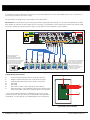
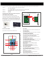
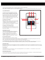
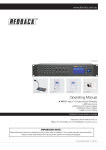
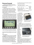
www.altronics.com.au
Operating Manual
A 4491/92 Input Source Selection Remote Plate
A 4491
A 4492
Overview
The A 4491and A 4492 wall plates allow remote selection of the zone’s input audio source and volume level.
In addition, when connected to the A 4478 or A 4479 local zone input wallplate, it allows the use of a local signal source,
such as a wired mic, radio mic or aux source, which VOX mutes the selected input from the A 4480.
The LCD displays the zone name, the input sources and zone and local input volume levels.
Note: The volume controls only adjust the volume of the 8 aux input sources, plus the local input (when used).
General and emergency paging from the A 4480 Audio Switcher will override these volume settings.
Features
• Remote selection of input audio source
• Volume control of zone input
• Volume control of local input
• Mute function
• Personal Identification Number 2 stage Lockout Function
• Zone Lockout
• DIP switch selectable Menu Lockout Function
• Provision for input of local microphone or line level audio via A 4478 or A 4479 wall plate
• Cat5e connection to A 4480
• Powered from the A 4480
Menu Accessed Features
• Enable/Disable Local Input
• Vox Sensitivity Level Adjustment
• Vox Delay Adjustment
• Disable Input Sources
• Backlight Timeout Adjustment
• Change Pin Number
• Change Zone (Wall plate ID)
• Lock/Unlock Screen
Redback® Proudly Made In Australia
User manual revision number: 1.2 07/10/2015
Connecting A 4491/92 remote plates to the A 4480 Audio Switcher
A maximum of eight A 4491/92 remote plates can be connected back to the A 4480 Audio Matrix, with a maximum of
one wall plate per zone as shown in Fig 1.
All connections are made using Cat5e leads or similar data cable.
Please note: On initial power up the wall plate ID will be requested to be entered. This number corresponds to the RJ45
port number on the back of the A 4480 that this wall plate is connected to. After entering this number you will be asked
to turn the A 4480 off and then back on again. The A 4480 will then complete a system update.
CAN
COM
EVAC
ALERT
Output
Levels
CHIME
Voice Chime Alert
Over
& Evac
SW1
INPUTS
Triggers
Manufactured in Australia By
Altronic Distributors Pty. Ltd.
www.altronics.com.au
CAUTION
RISK OF ELECTRIC SHOCK
OPEN BY QUALIFIED
PERSONNEL ONLY
230VAC
(AC Fuse 1A M205)
8
1 2 3 4
5
7 6
2
3
4
2
Input 1 & 2 XLR
1
ON
OFF
Phantom Power
(1) Input 1 ON
OFF
(2) Input 2 ON
OFF
(3)
Not Used
(4)
Not Used
1
SW2
8
1
2
3
Earth Lift
1
-
+
1
6
2
1
3
4
5
2
1
3
2
1
3
1
2
ON
ON
1 2 3 4
1 2 3 4
1 2 3 4
2
1
SW5
1
ON
OFF
Phantom Phantom
Power On Power Off
2
Mic Level Line Level
Switches 3 & 4 Not Used
1
2
1
3
2
1
3
2
2
1
3
3
8
(2A M205)
Paging Consoles / Preset Plates
Priority Input
USB
Keyboard
7
6
5
4
ZONE PLATES OR PRESET PLATES
3
2
1
Vox
Expansion IN Expansion OUT Level
ZONE1
ZONE1
ZONE1
ZONE1
ZONE1
ZONE1
ZONE1
ZONE1
INPUT 2
INPUT 2
INPUT 1
INPUT 2
INPUT 2
INPUT 1
INPUT 2
INPUT 2
INPUT 1
INPUT 2
INPUT 2
INPUT 1
INPUT 2
INPUT 2
INPUT 1
INPUT 2
INPUT 2
INPUT 1
INPUT 2
INPUT 2
INPUT 1
INPUT 4
INPUT 5
INPUT 6
INPUT 4
INPUT 5
INPUT 6
INPUT 4
INPUT 5
INPUT 6
INPUT 4
INPUT 5
INPUT 6
INPUT 4
INPUT 5
INPUT 6
INPUT 4
INPUT 5
INPUT 6
INPUT 4
INPUT 5
INPUT 6
INPUT 4
INPUT 5
INPUT 7
INPUT 8
LOCAL
INPUT
INPUT 7
INPUT 8
LOCAL
INPUT
INPUT 7
INPUT 8
LOCAL
INPUT
INPUT 7
INPUT 8
LOCAL
INPUT
INPUT 7
INPUT 8
LOCAL
INPUT
INPUT 7
INPUT 8
LOCAL
INPUT
INPUT 7
INPUT 8
LOCAL
INPUT
INPUT 7
INPUT 8
INPUT 1
ZONE VOL
MIN
Music
ON
L
R
Trigger
Volume
Vox
Level
2
1
CAT5 cable
Max 300M
L
R
1 2 3 4
3
INPUT 2
INPUT 2
INPUT 6
LOCAL
INPUT
A 4478
Mic
1 2 3 4
3
2
3
EMERGENCY INPUT
SW5
1 2 3 4
1 - Shield
2 - Hot
3 - Cold
24VDC In DC Fuse
!
7
2
3
SW3
SW
3
1 2 3 4
1 - Shield
2 - Hot
3 - Cold
Optional
Settings
SW4
(Not Used)
Dip Switch 3 Settings
1
3
ON
L
Lift/Chassis
A 4478 Local Microphone/
Local input wallplate.
(This is connected to the A 4491
zone selector plate to provide
a local VOX operated mic or line input.
Connection is via a 3 wire shielded
cable and euro block connector.
Maximum of 1 per A 4491 plate)
2
ON
R
Aux Input Sensitivity
DIP Switch Settings
SW1
ON OFF
(1) Input 1 0.3V 0.7V
(2) Input 2 0.3V 0.7V
(3) Input 3 0.3V 0.7V
(4) Input 4 0.3V 0.7V
SW2
ON OFF
(1) Input 5 0.3V 0.7V
(2) Input 6 0.3V 0.7V
(3) Input 7 0.3V 0.7V
(4) Input 8 0.3V 0.7V
OUTPUTS
ALERT - EVACUATION MODULE
LOCAL VOL
MIN
ZONE VOL
MIN
LOCAL VOL
MIN
ZONE VOL
MIN
ZONE VOL
LOCAL VOL
MIN
MIN
LOCAL VOL
MIN
ZONE VOL
ZONE VOL
LOCAL VOL
MIN
MIN
MIN
LOCAL VOL
MIN
ZONE VOL
MIN
ZONE VOL
LOCAL VOL
LOCAL VOL
MIN
MIN
MIN
Max 10M
A 4491 Zone Selector Wallplates.
Plate 1 must be connected to
input 1. Plate 2 to input 2 etc.
Zone plate ID number set by
the user via the menu.
Maximum of 1 zone plate per
zone and a maximum of
8 plates per system.
Fig 1
A 4491 Wiring Connections
A five way euro block connector is provided for connection to the
A 4478 wall plate. But only three of the connections are required as
listed above. It is advisable to use shielded cable for this connection.
7
1
2
3
4
5
ON
Positive audio connection from A 4478/79 wall plate.
Negative audio connection from A 4478/79 wall plate.
Ground audio connection from A 4478/79 wall plate.
Not Used
Not USed
DIP Switch (see DIP switch settings for more details).
RJ45 connection. (Cat5e provides power to the wallplate and routes local audio (fed from A 4478/79) back to the A 4480.)
6
1234
1
2
3
4
5
6
7
Fig 2. Rear view of A 4491
2 Redback® Proudly Made In Australia
www.altronics.com.au
DIP Switch Settings
On the rear of the wall plate as shown in Fig 2 there are four DIP switches which setup some of the plates options.
ON - PIN is required for access to the menu function.
OFF - PIN not required
ON - Backlight toggles on and off when buttons on screen pressed.
OFF- Backlight doesn’t change when buttons pressed.
Not Used
Not Used
Connection Diagram between the A 4491 TFT Wallplate
and the A 4478 Local Input Wallplate
Connecting the A 4478/79 local input wall plate to
the A 4491/92 Zone wall plate.
ON
Each A 4491/92 remote zone plate can have a
maximum of one A 4478 or A 4479 local input plate
connected, to provide a local audio override of the zone.
Both plates have a five way euro block connector used
for this purpose. It is advisable to use shielded cable for
this connection. NOTE : Only three of the connections are
required as shown in Fig3.
MIC+
MICGND
1234
Switch 1 Switch 2
Switch 3
Switch 4
A 4491
A 4478
Fig 3.
A 4478
A 4479
Screen Layout Guide
Fig 4 shows the layout of the A 4491/92 LCD.
1
ZONE1
13
INPUT 1
INPUT 2
INPUT 2
INPUT 4
INPUT 5
INPUT 6
INPUT 7
INPUT 8
LOCAL
INPUT
2
3
12
11
10
ZONE VOL
LOCAL VOL
55
40
9
8 7 6
4
5
1
Zone Label
This is the label set by the A 4480 used to identify the zone (e.g. Office).
2
Local Input Button
Press this button to activate the local input. The button will change to red when active.
3
Local input volume up button
Press this button to increase the local input volume.
4
Local input volume bar graph indicator
This bar provides a quick visual indicator of the local input volume.
5
Local input volume indicator
The number signifies the actual local input volume level.
6
Local input volume down button
Press this button to decrease the local input volume.
7
Sound indicator button
Press this button to mute/enable the sound.
8
Menu button
Use this button to enter the Menu functions.
9
Zone volume down button
Press this button to decrease the zone volume.
10
Zone volume indicator
The number signifies the actual zone volume level.
11
Zone volume bar graph indicator
This bar provides a quick visual indicator of the zone volume.
12
Zone volume up button
Press this button to increase the zone volume.
13
Input selection buttons 1-8
Use these buttons to select the desired input source.
Fig 4.
www.altronics.com.au
Redback® Proudly Made In Australia
3
Navigating The Menu
The menu button provides access to a host of options which are listed below.
Note : Access to the Menu can be restricted to only be available with a Personal Identification Number (PIN). This can be
activated by setting DIP Switch 1 to “ON” (See DIP settings).
1) Local Mic On/Off
The local input from the optional A 4478/79 wall plate can be enabled/disabled. Press the
button and follow the prompts to disable/hide
the local input button and volume controls. Once
hidden the local input icons will be greyed out.
They are no longer accessiible from the main
screen. To enable/show the local input press the
button and follow the prompts.
2) Change Pin Number
When DIP switch 1 is set to “ON” or if the plate
is locked, a Personal Identification Number (PIN)
is required to access the Menu function.
The pin number can be changed by pressing this
button and following the prompts.
8
7
1
2
3
LOCAL MIC
ON/OFF
CHANGE
PIN No.
CHANGE
ZONE
VOX
LEVEL
LOCK/
UNLOCK
SCREEN
BACKLIGHT
TIMEOUT
VOX
DELAY
DISABLE
INPUTS
EXIT
4
OK
5
3) Change Zone (Wall plate ID)
Use this option to set the wall plate ID. This must
be set to match the RJ45 port connection on the
rear of the A 4480.
4) Backlight Timeout
The time the backlight remains on after the
screen has been touched can be adjusted. The
time can be adjusted between 0 and 600
seconds. Setting the time to zero keeps the
backlight on continually. Set the time to 1 sec
and the backlight will turn off after 1 sec etc.
6
Fig 5. A 4491/92 Menu Screen
5) Lock/Unlock Screen
There are two levels of user lockout available.
The first level locks the inputs so that the input source cannot be changed by pressing the input buttons on the LCD.
Note : The volume and mute buttons are still accessible at this lockout level.
The second level locks out the entire wall plate so that none of the buttons function.
Press the Lock/Unlock Screen button and follow the prompts. Note: To unlock the plate after locking the first level, the
user will have to proceed to the Lock Entire plate function and then have access to the Unlock function.
6) Disable Inputs
By using this function any of the eight input sources can be disbaled, so that they are not available to the zone. Press the
Disable Inputs button and then highlight the zones to be disabled. Once the inputs are disabled the buttons will be greyed
out on the LCD.
7) Vox Delay
The amount of time the VOX delay is active can be adjusted from 0 to 30 seconds in 1 sec increments. Press the VOX
Delay button and follow the prompts.
8) Vox Sensitivity Level
The vox sensitivity of the local input can be set here. The VOX sensitivity can be set between 1 and 99 with 99 being the
most sensitive. Press the VOX Sensitivity Level button and follow the prompts.
4 Redback® Proudly Made In Australia
www.altronics.com.au