1
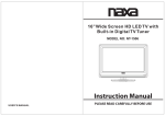
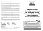
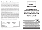
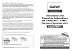
Installation and
Operating Instructions for
community water savings
To outlets
PRO
Rainwater
NOTE: Prior to installation remove the inlet and outlet pipe,
transport plugs & associated seals from the suction and/or
discharge ports.
WARNING : The RainBank®PRO system and associated pipework operate
under pressure. Under no circumstances should the RainBank®PRO System or
associated pipework be disassembled unless the internal pressure of the unit
has been relieved. Failure to observe this warning will expose persons to the
possibility of personal injury and may also result in damage to the pump, pipework
or other property.
WARNING: Failure to follow these instructions and comply with all applicable
codes may cause serious bodily injury and/or property damage.
Please pass these instructions on to the operator of this equipment.
CONTENTS
RainBank®PRO PUMP SET COMPONENTS
3
CONNECTION TO MAINS SUPPLY
4
PRESSURE SWITCH
4
TANK PRECHARGE
4
CHOOSING A SITE
4
POWER CONNECTION
4
ELECTRICAL POWER SURGE PROTECTION
4
PIPE CONNECTIONS
5
WHERE TO USE CHECK VALVES AND FOOT VALVES
5
ABRASIVE METALS
5
INSTALLATION WITH A MAINS PRESSURE HOT WATER SYSTEM
5
PRIMING AND OPERATION
5
CONTROL BOX OPERATION
6
CONNECTION DIAGRAM – 240V
7
CONNECTION DIAGRAM – 415V
8
TYPICAL INSTALLATION
9
MAINTENANCE
10
PRESSURE SETTINGS
10
TROUBLE SHOOTING CHECK LIST
11
TERMS AND CONDITIONS
12
Prior to using this pump you must ensure that:
• The pump is installed in a safe and dry environment
• The pump enclosure has adequate drainage in the event of leakage
• Any transport plugs are removed
• The pipework is correctly sealed and supported
• The pump is primed correctly
• The power supply is correctly connected
• All steps have been taken for safe operation
Appropriate details for all of these items are contained in the following Installation and Operating Instructions. Read
these in their entirety before switching on this pump. If you are uncertain about any of these Installation and Operating
Instructions please contact your Davey dealer or the appropriate Davey office as listed on the back of this document.
2
Congratulations on your purchase of a high quality, Davey RainBank®PRO pump set. All components have been designed
and manufactured to give trouble free, reliable operation.
RainBank®PRO PUMP SET
11
9
1
8
7
5
To outlets
Rainwater
2
6
10
4
RainBank®PRO pump set components:
1. VM pump and motor
2. Base plate
3. Check valve
4. Discharge manifold
5. Pressure gauge
6. Pressure switch
7. Isolation valve
8. Flow switch
9. Pressure tank
10.Dual check valve (mains water entry)
11. RainBank®PRO control box
3
3
See page 9 for standard
installation drawing
Connection of Mains Scheme or Town Water
Supply to either Suction or Discharge of Pump
Most Water Supply Authorities have strict regulations regarding direct connection of
pumps to mains water supplies. In most cases an isolating storage tank is required
between mains supply and pump — Davey also recommend this method. Directly applied
mains pressure can exceed pump operating pressure and damage pump.
Davey Water Products Pty. Ltd. cannot accept responsibility for loss or damage
resulting from incorrect or unauthorised installations.
Pressure Switch settings
Your Davey RainBank®PRO pump set should have the correct pressure switch setting
for zero suction lift. If your pump is installed on a suction lift you may need to adjust the
pressure setting to suit.
Any adjustment of the pressure switch settings should be made according to the pump
curve*. The cut-out pressure should never be higher than 90% of the maximum pump
shut head pressure OR higher than the maximum operating pressure for the pressure
tank and the cut-in pressure should be set within the pump curve*. For standard pressure
switch settings refer to the table in the maintenance section of these instructions.
XMP12 Adjustments
To adjust the cut-out (high) pressure of the system, turn the large dial (1) in the desired
direction: + (CW) for higher pressure, – (ACW) for lower pressure.
To adjust the cut-in (low) pressure of the system, turn the smaller screw (2) in the desired direction: + (ACW) for higher
pressure, – (CW) for lower pressure.
FLOW SWITCH SENSITIVITY ADJUSTMENT
There are two methods of setting the point at which the F25 flow switch operates, in relation to any given flow. By far
the most effective is careful trimming of the paddle length. The second method should only be used to fine tune an
installation. There is a sensitivity adjusting screw located at the upstream end of the switch under the end of the electrical
housing. This is accessible by removing the hexagon headed plug, and adjustable using a broad bladed screwdriver. As
supplied, the screw is wound fully in. This setting makes the switch least sensitive to liquid impinging on the paddle. The
screw may be wound anticlockwise, to increase the sensitivity. That is, to make the switch respond to lower flows, or to a
more smaller area of paddle eposed to the flow. The screw should never be removed or wound out more than 6 full turns,
and never wound in beyond its stop. The switch will not operate if the screw is removed.
Tank Precharge
The pressure tank fitted to your Davey pump set should be pre-charged with air to a value of 15kPa below the cut
in pressure. For standard tank pressure settings refer to the table in the maintenance section on page 10 of these
instructions.
Choosing a Site
Choose a site with a firm base and as close to the water source as possible with correct power supply. Make sure your
pressure pump is always connected to an adequate, reliable source of clean water.
Housing your Davey Pump: To protect your pump from the weather, make sure the housing is both water proof and frost
free and has adequate ventilation.
The pump set should be mounted on its base in a firm dry area allowing for drainage, to avoid damage due to flooding
etc., that over time may occur from leaking pipe joints or pump seals.
WARNING: Some insects, such as small ants, find electrical devices attractive for various reasons.
If your pump enclosure is susceptible to insect infestation you should implement a suitable pest
control plan.
Power Connection
Only connect the pump set to the power supply designated on the pump and motor label.
Single-phase pumps up to 1.5kW have a built in thermal overload and have been provided with a 10 amp cable and plug
for connection to a standard power outlet.
Single-phase 2.2kW pumps have a built in thermal overload and have been provided with a 15 amp cable and plug for
connection to a standard 15 amp power outlet.
Do not use long extension leads as they cause substantial voltage drop, poor pump performance and may cause motor
overload.
The electrical connections and checks must be made by a qualified electrician and comply with
applicable local standards.
* Adjusted for site conditions, i.e. suction
life or positive suction pressure
4
Electrical Power Surge Protection
An electrical power surge or spike can travel along the supply lines and cause serious damage to your electrical
equipment. The RainBank®PRO controller fitted to this system has a metal oxide varistor (MOV) fitted to help protect its
circuit. This MOV is a “sacrificial” device, meaning that it is gradually damaged every time it takes a surge. The MOV is
not a lightning arrestor and may not protect the control unit if lightning or a very powerful surge hits the pump unit.
Degradation of the MOV is a non-warrantable failure. If the installation is subject to electrical power surges or lightning
we strongly recommend the use of suitable additional surge protection devices on ALL electrical equipment.
In accordance with AS/NZS 60335.2.41 we are obliged to inform you that this appliance is not intended for use by young
children or infirm persons unless they have been adequately supervised by a responsible person to ensure that they can
use the appliance safely.
NOTE: Young children should be supervised to ensure that they do not play with the appliance.
Pipe Connections
For best performance use pipes at least the same diameter as the pump’s inlet and delivery outlet opening. Larger
diameter pipe may be used to minimise resistance to flow when pumping longer distances.
Use unions at pipe connections to enable easy removal and servicing. Use sufficient tape to ensure an airtight seal but
don’t over tighten. To prevent strain on pump threads always support heavy inlet and outlet pipes. If there is a likelihood
that the water supply may contain solid particles such as pieces of plant or vegetable matter, a suction strainer should be
installed before the pump to avoid blocking of pump. Lay suction pipe at a constant gradient to avoid air pockets which
may reduce pump efficiency.
NOTE: Suction leaks are the largest cause of poor pump performance and are difficult to detect.
Ensure all connections are completely sealed using thread.
Where to use Check Valves and Foot Valves
Installations with flooded suction require a gate valve so water supply can be turned off for pump removal and servicing.
On installations with a suction lift a good quality foot valve with strainer is required. It is not recommended to fit both a foot
valve and the check valve in a suction lift installation.
Abrasive Materials
The pumping of abrasive materials will cause damage to the pressure system which will then not be
covered by the guarantee.
For Automatic Pressure Pumps Installed with a Mains Pressure
Hot Water System
To protect your system from damage caused by back pressure from hot water systems, you should always have installed
on the hot water inlet an approved non-return valve.
Priming and Operation
1. After installing pump set shut the discharge gate valve.
2. Fill pump, suction line and discharge assembly with water via the priming ports. On flooded suction simply open
suction gate valve to the pump set. When full, fit priming plugs and hand tighten firmly.
3. Ensure an outlet nearest to the pump is open.
4. Ensure all valves in the suction line are open.
5. Switch pump on and partially open the discharge gate valve.
6. Prime should be established almost immediately and a strong flow of water should be evident from the outlet. Allow
water to flow for approximately 20 seconds to expel air.
7. If little or no flow is evident from the outlet, switch pump off at the power point and repeat from step 1 ensuring that
there is adequate supply of water available to the pump.
8. Once water flow has been achieved, shut the discharge isolation valve. The pump should slowly build up pressure (on
the gauge) and turn off at the appropriate cut-out pressure.
9. Check the pressure switch settings by opening and closing the discharge isolation valve slowly and reading pressure
on the pressure gauge. Adjust if necessary. Refer section on pressure switch.
10.To prime the discharge pipework, partially open discharge isolation valve and then systematically open & close all
outlets on the system to expel the air within the discharge pipework.
5
RainBank®PRO Control Panel Operation
The following explanations describe the
RainBank®PRO control panel and its operation.
MAINS/RAIN WATER SWITCHING
Indicators
LED indicators are used to display
•
•
•
•
•
•
POWER ON
Mains power supply is on
MAINS WATER
Mains water supply is in use
RAINWATER
Pumped rainwater is in use
Tank Low Level
Low level in water storage tank, mains water will
be in use
Pump Fault
Pump is in fault and mains water will be in use
Solenoid Test
While depressed mains water solenoid will open,
and pump will not run.
PUMP CONTROL
Indicators
LED indicators are used to display
• POWER ON
Mains power supply is on
• PUMP RUN
Pump is operating
• LOW FLOW ALARM
Water flow failure (60 second timer)
• PUMP OVERLOAD
Thermal overload on pump contactor has tripped
• FAULT RESET
Resets the LOW FLOW fault
PUMP MODE SELECT BUTTON
ALARM FUNCTIONS
• AUDIO ALARM
Will automatic mute after 5 minutes
• VISUAL ALARM and STROBE
Will continue to function until the fault is
corrected or the fault reset button is pressed.
• AUTO
Pump ready to operate from the control input
devices
• OFF
Pump selected to not operate
• MANUAL
The pump will operate in manual mode for 21/2
minutes then the control panel will switch to
AUTO.
6
RainBank®PRO Single Phase Wiring Diagram – 240V
7
RainBank®PRO Three Phase Wiring Diagram – 415V
8
To outlets
SOLENOID VALVE
DUAL CHECK VALVE
(MAINS CONNECTION)
6
7
9
TOP VIEW
2
MAINS SUPPLY POWER
5
3
LOW LEVEL ALARM FLOAT
4
7
PADDLE TYPE FLOW SWITCH
3
6
PRESSURE SWITCH
2
5
CONTROL PANEL
1
1
PRESSURE
TANK
RainBank®PRO Pump Set
100mm minimum
4
Rainwater Tank
RainBank®PRO Typical Installation
Maintenance
The only regular attention your new pump set requires is to check the pressure tank’s air charge every 6 months.
This can be checked at the air valve with a tyre gauge. Do not charge tank to a higher pressure than 15 kPa below cut-in
pressure setting.
To check air pressure in tank:
1. Switch off pump.
2. Open outlet nearest to pump to release water pressure.
3. Remove air valve cap from top of Supercell tank and charge tank to correct pressure using air pump and check with
tyre gauge.
4. Reprime system and switch on.
NOTE: Your pump is designed to operate as an automatic pressure system.
The pressure tank will require a specific precharge air pressure dependent upon model.
While your pressure tank may have been precharged in manufacture, the precharge pressure should
be checked upon installation and every 6 months thereafter. Follow the instructions on the tank. As a
guide, the precharge settings are listed below:–
Pressure Settings
Pressure Settings*
Tank
Cut-in
Cut-out
Pressure
Pump
Motor
Standard Tank
kPa
kPa
kPa
VM5-5
1.1
HP24+
200
450
185
VM5-6
1.1
HP24+
300
550
285
VM5-7
1.5
HP24+
300
650
285
VM5-8
1.5
HP24+
300
700
285
VM10-4
1.5
HP24+
300
400
285
VM10-5
2.2
HP24+
350
500
335
VM10-6
2.2
HP24+
400
600
385
VM10-7
3
HP24+
500
700
485
VM16-3
3
HP24+
250
400
235
VM16-4
4
HP24+
350
550
335
VM16-6
5.5
HP24+
450
650
435
*Standard settings. Can be adjusted to suit site conditions.
10
Trouble Shooting Check List
A) MOTOR RUNS WHEN SWITCHED ON BUT DOES NOT PUMP.
1. Suction line and pump body not filled with water.
2. Air leaks in suction lines or suction pipe not under water.
3. Air trapped in suction lines (also possible with flooded suction due to uneven rise in piping: eliminate humps and
hollows).
4. No water at source or water level too low.
5. Valve on suction line closed.
B) PUMP SWITCHES ON AND OFF FREQUENTLY (CYCLING).
1. Check that tank air pressure is correct.
2. Leaking taps, float valves etc. Check plumbing.
3. Leaking check valve/foot valve.
4. Pressure Switch may require adjustment to cater for flooded suction installations – consult your Davey dealer for
advice.
C) MOTOR DOESN’T START WHEN SWITCHED ON.
1. Power not connected.
2. Supply voltage too low.
3. Motor not free to turn e.g. a jammed impeller.
4. Internal motor fault.
NOTE: For protection, single phase motors up to 2.2kW are fitted with an automatic “over
temperature” cut-out. Constant tripping of this overload device indicates a problem e.g. low voltage
at pump, excessive temperature (above 40°C) in pump enclosure.
Warning: Automatic resets may allow the pump to restart without warning. Always disconnect the
pump motor from the electrical supply before maintenance or repairs.
WARNING: When servicing or attending the pump, always ensure power is switched off and lead
unplugged. Electrical connections should be serviced only by qualified persons. If the electrical
supply lead of this pressure system is damaged, it must only be replaced by authorised Davey
service personnel as special tools are required.
Care should also be taken when servicing or disassembling the pump to avoid possible injury from
hot pressurised water. Unplug pump, relieve pressure by opening a tap on the discharge side of the
pump and allow any hot water in the pump to cool before attempting to dismantle.
WARNING: Do not use hydrocarbon based or hydrocarbon propelled sprays around the electrical
components of this pump.
11
Davey® Repair or Replacement Guarantee
In the unlikely event in Australia or New Zealand that this Davey product develops any malfunction
within two years of the date of original purchase due to faulty materials or manufacture, Davey will at
our option repair or replace it for you free of charge, subject to the conditions below.
Should you experience any difficulties with your Davey product, we suggest in the first instance that
you contact the Davey Dealer from which you purchased the Davey product. Alternatively you can
phone our Customer Service line on 1300 367 866 in Australia, or 0800 654 333 in New Zealand, or
send a written letter to Davey at the address listed below. On receipt of your claim, Davey will seek to
resolve your difficulties or, if the product is faulty or defective, advise you on how to have your Davey
product repaired, obtain a replacement or a refund.
Your Davey Two Year Guarantee naturally does not cover normal wear or tear, replacement of product
consumables (i.e. mechanical seals, bearings or capacitors), loss or damage resulting from misuse
or negligent handling, improper use for which the product was not designed or advertised, failure to
properly follow the provided installation and operating instructions, failure to carry out maintenance,
corrosive or abrasive water or other liquid, lightning or high voltage spikes, or unauthorized persons
attempting repairs. Where applicable, your Davey product must only be connected to the voltage
shown on the nameplate.
Your Davey Two Year Guarantee does not cover freight or any other costs incurred in making a claim.
Please retain your receipt as proof of purchase; you MUST provide evidence of the date of original
purchase when claiming under the Davey Two Year Guarantee.
Davey shall not be liable for any loss of profits or any consequential, indirect or special loss, damage or
injury of any kind whatsoever arising directly or indirectly from Davey products. This limitation does not
apply to any liability of Davey for failure to comply with a consumer guarantee applicable to your Davey
product under the Australian or New Zealand legislation and does not affect any rights or remedies that
may be available to you under the Australian or New Zealand Consumer Legislation.
In Australia, you are entitled to a replacement or refund for a major failure and for compensation for
any other reasonably foreseeable loss or damage. You are also entitled to have the goods repaired or
replaced if the goods fail to be of acceptable quality and the failure does not amount to a major failure.
Should your Davey product require repair or service after the guarantee period; contact your nearest
Davey Dealer or phone the Davey Customer Service Centre on the number listed below.
For a complete list of Davey Dealers visit our website (davey.com.au) or call:
AUSTRALIA
NEW ZEALAND
Customer Service Centre
6 Lakeview Drive,
Scoresby, Australia 3179
Ph:
1300 367 866
Fax:
1300 369 119
Website:davey.com.au
Customer Service Centre
7 Rockridge Avenue,
Penrose, Auckland 1061
Ph:
0800 654 333
Fax:
09 527 7654
Website:daveynz.co.nz
Davey Water Products Pty Ltd
Member of the GUD Group
ABN 18 066 327 517
® Davey is a registered trade mark of Davey Water Products Pty Ltd.
© Davey Water Products Pty Ltd 2011.
P/N 401900-2 supersedes P/N 401900-1
* Installation and operating instructions are included with the product when purchased new.
They may also be found on our website.