1
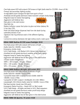
OPERATING INSTRUCTIONS LP-FLOWETCH-COMPACT Semi-automatic marking system Trend Marking Systems PO Box 1311 Castle Hill NSW 2154 AUSTRALIA Tel.: +61 2 96299535 Fax.: +61-2-96297535 Email: [email protected] Internet: http://www.trendmarking.com.au flowetch-compact-manual-v104 OPERATING INSTRUCTIONS LP-FLOWETCH-COMPACT Safety tip x Only authorised persons may open the machine. Unplug the machine before opening. x In handling the electrolyte you expose yourself to organic and inorganic oxide substances in conjunction with natural water. x Please request a safety material data sheet for each electrolyte number as per standard 91/155/EWG. Application The below described unit is designed to mark products with metal, electrically conductive surfaces in conjunction with electrolyte. Proper functioning of this unit depends upon correct treatment and maintenance of the system. The operation and maintenance instructions must be studied carefully by all operating personnel before the system is used. Copyright All parts of this technical document including any patents described or trademarks contained therein are the sole property of ÖSTLING Markiersysteme GmbH Solingen, Germany. Without prior approval no part of this document may be duplicated or made available to a third party. No misuse of this manual is permitted. No form of misrepresentation of the content of this document is permitted. Liability For any error in shipment or damage caused during shipment our liability is limited to those conditions outlined in the Terms of Delivery. Duration of the warranty is stated in the Terms and Conditions. We are not responsible for damage caused from improper handling of the equipment or for damage caused by disregarding the operating instructions. ÖSTLING Marking Systems for Products and Packaging 1 OPERATING INSTRUCTIONS LP-FLOWETCH-COMPACT EU - Conformity declaration We herewith declare that the construction of the following illustrated unit conforms to all regulations as required by EU guidelines. Alterations to the machine not performed by our technicians invalidates this declaration. Machine type: Electrolytic marking machine Model: LP-FLOWETCH Marking machine: EU-CLASSIC 300 / EU CLASSIC 500 Machine guidelines: altered through: 89/392/EWG 91/368/EWG; 93/44/EWG; 93/68/EWG; Low tension guideline: altered through: 73/23/EWG 93/68/EWG Electromagnetic agreement: altered through: 89/336/EWG 91/263/EWG; 92/31/EWG; 93/68/EWG; Applied harmonized norms: EN 292-1; EN 292-2; EN 60 204-1; EN 50 081-1; EN 50 082-1; EN 60 947; EN 60 439; Applied national standards: DIN VDE 0100; DIN VDE 0110; DIN VDE 0113; DIN VDE 0660 Place, date: Solingen, 14.11.97 Legally binding signature: Rolf Östling This declaration conforms to the terms of the applicable guidelines, and is not an assurance of quality. The safety precautions included in delivery of this produce are to be followed. ÖSTLING Marking Systems for Products and Packaging 2 OPERATING INSTRUCTIONS LP-FLOWETCH-COMPACT CONTENTS Page 1 General information.................................................................... 4 2 Function description ................................................................... 4 3 Unit drawing ............................................................................... 5 4 Operating the machine ............................................................... 6 4.1 Tungsten carbide outlet (Option)...........................................................6 4.2 Stencil assembly .....................................................................................7 4.3 Preparing the marking head ..................................................................7 5.0 Programming procedure - EU Classic .......................................... 8 5.1 Starting up................................................................................................8 5.1 Marking voltage .........................................................................................9 5.2 Marking time ..............................................................................................9 5.3 Pumping time .............................................................................................9 5.4 Retarder (Option)........................................................................................9 5.5 Counter (Option) ......................................................................................10 5.6 Original settings .......................................................................................10 6 The Marking Process ................................................................. 11 7 Maintenance.............................................................................. 12 8 Accessories ................................................................................ 12 9 Troubleshooting ........................................................................ 13 9.1 Problem: No mark at all ...........................................................................13 9.2 Problem: Mark is not clear........................................................................13 9.3 Problem: Black spots around the mark ......................................................13 10 Choice of electrolytes............................................................. 15 ÖSTLING ÖSTLING ......................................................................... 16 ÖSTLING Marking Systems for Products and Packaging 3 OPERATING INSTRUCTIONS LP-FLOWETCH-COMPACT 1 General information The LP-Flowetch is a semi-automatic marking system made of the EU Classic series, the electrolyte pump, and the mechanics of automation (basin, tripod, and product holder). 2 Function description The LP-FLOWETCH is for marking products with metallic, electrically conductive surfaces. It does not matter if the product is hardened, homp steamed, bronzed, chromed, nickel plated, large, small, flat, or round. The supplied voltage is 115 V or 230 V (AC), the output voltage can be set at infinite settings between 0 - 30 V (AC or DC), power can be set at 310 VA or 510 VA. In addition, a timer can delay marking times infinitely between 0,6 - 10 seconds. The marking head gets electrolyte via a pump. Working in conjunction with electric current and electrolyte, an electrochemical process takes place which marks an image on the product via a prepared stencil. EU CLASSIC 300 EU CLASSIC 500 Entry voltage 115 V or 230 V, AC 115 V or 230 V, AC Exit voltage 0 - 30 V (AC or DC) 0 - 30 V (AC or DC) Power 310 VA 510 VA Dimensions (L x W x H) 140 x 380 x 220 mm 140 x 380 x 220 mm EMV tested EN 50081-1; EN 50082-1 EN 50081-1; EN 50082-1 ÖSTLING Marking Systems for Products and Packaging 4 OPERATING INSTRUCTIONS LP-FLOWETCH-COMPACT 3 Unit drawing Pos. 1 Pos. 2 Pos. 3 Pos. 4 Pos. 5 Pos. 6 Pos. 7 Pos. 8 Pos. 9 Power switch Key n Key p (Werte verringern) Key (Enter) Key MENU Key =/a (DC/AC) Key Automatic Key Timer Key Pump Pos. 10 Pos. 11 Pos. 12 Pos. 13 Pos. 14 Pos. 15 Pos. 16 Pos. 17 Pos. 18 LED’s Display Throttle for cylinder speed Pressure regulator Socket for pump Pressure meter Air supply Power cord Electrolyte hose ÖSTLING Marking Systems for Products and Packaging Pos. 19 Pos. 20 Pos. 21 Pos. 22 Pos. 23 Pos. 24 Pos. 25 Pos. 26 Electrolyte hose Limit plate Marking head Limit plate Stencil Negatice contact Valve Socket for foot switch 5 OPERATING INSTRUCTIONS LP-FLOWETCH-COMPACT Pos. Pos. Pos. 4 33 Electrolyte runoff pump 34 Electrolyte entry pump 35 Connector 230 V, AC Operating the machine Set the marking voltage over the power cord with voltage (Pos. 18) and set the connector (Pos. 35) of the electrolyte pump in the accompanying connection (Pos. 17) the marking voltage. Bind the socket with the footswitch with the entry socket (Pos. 15) and solenoid valve plug (Pos. 24) with the entry socket (Pos. 19), which are on the back of the control. Please connect with the included cables (red and blue) the marking output (Pos. 13 and Pos. 14) with the negative contact point (blue) as well as the marking head (red). To that you will find on the side of the basin a fitting connecting piece. Close Electrolyte outlet tube (Pos. 26) on the filter mechanism of the Electrolyte pump (Pos. 33). Then connect the electrolyte supply of the pump (Pos. 34) with the cut-off valve (Pos. 25). Equalise air pressure as indicated on the valve/outlet/gauge (Pos. 22). For this use a tube PUN8. Now fill the pump with electrolyte (approx. 3,5 Litres). 4.1 Tungsten carbide outlet (Option) If you would like to use the tungsten carbide option you will find an appropriate socket (Pos. 16), which must be connected to the marking head. ÖSTLING Marking Systems for Products and Packaging 6 OPERATING INSTRUCTIONS LP-FLOWETCH-COMPACT 4.2 Stencil assembly There are several ways to assemble the stencils, depending on the nature of the product to be marked. The different manners to mark the product are described below. We will be happy to assist you with any questions you might have. 4.3 Preparing the marking head The marking surface of the marking head is covered with black felt and conductive net for black marking. For deep marking, use the green or grey felt. Stencil assembly for: x flat products Stencil (glued) Stencil cover (glued) Positive contact Electrolyte supply x flat products (cassette assembly) Felt holder or Cassette ÖSTLING Marking Systems for Products and Packaging Conductive net Felt holder Felt Stencil (glued) Stencil cover (glued) Conductive net Felt 7 OPERATING INSTRUCTIONS LP-FLOWETCH-COMPACT x for round products (sequence as above) The maximum writing field is ca. 150q Positive contact In case of a scarred marking head we recommend that you increase the delay time. Here a current passes through after the product is pressed by the pneumatically. Otherwise this can lead to unclear marks. 5.0 Programming procedure - EU Classic 5.1 Starting up After being switched on, the unit will be in the Main Menu mode. The values and settings last adjusted will be kept when the unit is switched off. The display shows for example U=08,0V MT=04,0s x The keys A, T, P and the START-Input (foot switch) can be operated within the main menu only. x The keys MENU, n, and p have no function within the main menu. x The key is used to leave the main menu and enter the sub menu marking voltage. ÖSTLING Marking Systems for Products and Packaging 8 OPERATING INSTRUCTIONS LP-FLOWETCH-COMPACT 5.1 Marking voltage Within the sub menu marking voltage only the keys n, p, , MENU and =/a can be operated. x The key =/a allows you to switch between DC and AC voltage. The LED´s above the key show the present current flow. x The key n (Pos. 2) increases, the key p (Pos. 3) decreases the output voltage by 0.2 Volt (Umin = 0.2 V; Umax = 30.0 V) each. x By operating the key the adjusted value is accepted. x By operating the MENU key (Pos. 5) the adjusted value is not accepted, and the main menu is re-entered. x From the sub menu marking voltage adjustment, you may enter the sub menu marking time. 5.2 Marking time In the sub menu marking time only the keys n, p, and MENU can be operated. x The key n increases, the key p decreases the marking time MT by 0.1 second each (MTmin = 0.1 s; MTmax = 15.0 s). x By using the key the new value is accepted, and you will re-enter the main menu. x By using the key MENU the new value is not accepted, and you will re-enter the main menu. x If the pumping time option is activated, it is possible to enter the sub menu pumping time. 5.3 Pumping time In the sub menu pumping time only the keys n, p, and MENU can be operated. x The key n increases, the key p decreases the pumping time PT by 0.1 second each (PTmin = 0.1 s; PTmax = 10.0 s). x By operating the key the new value is accepted, and you will re-enter the main menu. x By operating the key MENU the new value is not accepted, and you will re-enter the main menu x If the option delay is activated, you may enter the sub menu delay. 5.4 Retarder (Option) In the sub menu retarder only the keys n, p, and MENU can be operated. x The key n increases, the key p decreases the delay by 0.1 second each (RTmin = 0.1 s; RTmax = 10.0 s). ÖSTLING Marking Systems for Products and Packaging 9 OPERATING INSTRUCTIONS LP-FLOWETCH-COMPACT x By operating the key the new value is accepted, and you will re-enter the main menu. x By operating the key MENU the new value is not accepted, and you will re-enter the main menu. 5.5 Counter (Option) You can see the actual value of markings on the display: Counter= 00022 By operating the key p the counter will be reset. 5.6 Original settings All settings can be reset to their original settings by depressing the key MENU and turning the unit on. Output voltage U = 8.0 V Marking time MT = 2.0 s Pumping time off; PT = 0.00 s Delay off; DT = 0.01 s Type of output voltage: AC AC-LED = on; DC-LED = off Timer function off; T-LED = off Output magnet valve (24 V) off; A-LED = off Output Pump (230 V) off; P-LED = off Counter 00000 Language German ÖSTLING Marking Systems for Products and Packaging 10 OPERATING INSTRUCTIONS LP-FLOWETCH-COMPACT 6 The Marking Process x Set the marking voltage and turn on the unit by pressing (Pos. 1). x Depending on the material to be marked, select the appropriate electrical current with the key =/~. Refer to section 10 to select the appropriate electrolyte. Also select the exit voltage to an appropriate level as indicated in the display window (Pos. 11). x Set your desired marking time (see point 5.3) x Now touch the Automatic key (Pos.7) and Timer key (Pos. 8). The appropriate LED lights should be showing. x Next touch the Pump key (Pos.9) so that the electrolyte moves from the pump to the marking head. When the marking head is soaked with electrolyte, you may turn off the pump. Pump time is described under point 5.4 For every marking cycle, electrolyte should be added in order to accommodate the pump times. x Lay the product to be marked on the marking head (Pos. 29) and position it with help of the side fastening device (Pos. 27 and 28). Now depress the footswitch. x The negative contact (Pos. 31) goes down and presses the product to be marked on the stencil (Pos. 30) and remains there for the allotted time in the marking time. In order to produce a satisfactory impression the cylinder needs ca. 3 - 5 bar, as shown by the pressure gauge (Pos. 32). x You may adjust pressure with the installed pressure (Pos. 21). The negative contact should quickly and evenly pass the product. The speed of the Cylinder is adjustable with the choker valve (Pos. 20). x After completing the set marking time, the cylinder rises and the product can me removed. x If the option counter is activated the display shows after a few seconds the actual value of markings: Counter = 00156 The counter adds the marking process (s. display). After a product charge has been marked and the required counter reading has been reached, the counter can be returned to zero (see point 5.5). ÖSTLING Marking Systems for Products and Packaging 11 OPERATING INSTRUCTIONS LP-FLOWETCH-COMPACT x General instructions for voltage and marking time cannot be provided in the operation instructions, as these parameters are depending upon the product to be marked. x In order to obtain a long life time of the stencil, we recommend to strive for a low voltage and short marking time. x After finishing the marking, felt, conductive net and stencils should be cleaned with ordinary tap water. x Should you notice that the marking quality deteriorates, please inspect felt and conductive net, as during marking an operational carbonisation of the felt takes place i.e. felt and net have to be replaced from time to time. x To prevent a short circuit, please take care, that the marking head does not get in direct contact with the product fixture. 7 Maintenance Regular maintenance is not necessary. Should there be a problem, however, please contact our service department. Opening the unit without proper authorisation voids the warranty. 8 Accessories The modular construction of our machine makes it possible to automate the marking process. Our technicians will be pleased to answer any questions you might have. ÖSTLING Marking Systems for Products and Packaging 12 OPERATING INSTRUCTIONS LP-FLOWETCH-COMPACT 9 Troubleshooting 9.1 Problem: No mark at all Please check: x Is the main power cable connected and the etching machine switched on? x Are the electrode and pneumatic cables correctly connected? x Has the voltmeter been activated? x Is the marking head moistened with electrolyte? x Is the electrolyte reservoir filled with electrolyte? Note: x You can only mark products which conduct electricity. x Painted, anodised or otherwise coated surfaces are not suitable for marking by electrolytic etching. 9.2 Problem: Mark is not clear x Make sure that the stencil is clean. x Wash the stencil in water to remove oxides. x Also make sure that the surface of the product is clean. Wipe off dirt or excess oil with a dry cloth before marking. x Is the marking head moistened with electrolyte? x Normal usage yields slight discoloration of the stencil, for this reason we recommend that you change stencils from time to time. 9.3 Problem: Black spots around the mark x The stencil is worn out or has been treated improperly and holes have developed in the red portion of the stencil. Replace the stencil with a new one or prolong the life of the old stencil by covering over the damaged areas with adhesive tape. ÖSTLING Marking Systems for Products and Packaging 13 OPERATING INSTRUCTIONS LP-FLOWETCH-COMPACT Please contact us if: x you have technical problems. x you need marked samples. x you need any additional accessories such as marking heads in different sizes, felt, electrolyte for other types of materials, stencil covers, fixtures, etc. you need information about our other products such as pad printing, needle embossing, laser marking or ink-jet-systems. ÖSTLING Marking Systems for Products and Packaging 14 OPERATING INSTRUCTIONS LP-FLOWETCH-COMPACT 10 Choice of electrolytes Type of marking Black-etching Type of voltage Voltage AC 8V Marking time 1-2 s Felt Black with Material Stainless steel conductive net Alloyed Steel Steel Electrolyte 6744, 70 ,72 ,SP1 6744 Neutralise with N8 676, 74, 67/10/3, 676R74 Corrosion free electrolyte The marking time is dependent on coating thickness with chrome products. In case of unclear marking, send us sample. Chrome , Nickel Zinc coated White-etching AC 8V 1-2 s 75 639, 6578 Titanium 6578 Hard metal 332/2 Black with Black oxidised conductive net (Homo steamed) Remarks Neutralise with N8 114 Soft Depending of alloy, the hard metal option may be necessary. Neutralise with N8 119 Medium 117 Strong Deep-Etching DC approx. 20 -25 V >3s Green Brass DE40, DE90 Aluminium DE40, DE90 In the case of deep etching the marking time is dependent on the desired depth. This can last up to a few minutes. Electrolyte must be discarded after the marking process is complete ÖSTLING Marking Systems for Products and Packaging 15