1
,QVWDOOLQJDQG2SHUDWLQJ,QVWUXFWLRQV
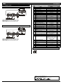
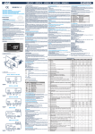
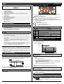
14. CONNECTIONS
15. DEFAULT SETTING VALUES
Label
Set
Hy
LS
US
Ot
OdS
AC
CCt
COn
R oom
14.1 XR30C: 8A COMPRESSOR
8(3)A250V
8(3)A250V
Aux/ N.C .
Alarm
Hot Key
Comp
COF
Line
CH
CF
rES
IdF
MdF
dFd
dAd
ALc
12Vac/dc supply: connect to the terminals 7 and 8.
24Vac/dc supply: connect to the terminals 7 and 8.
120Vac supply: connect to the terminals 7 and 8.
14.2 XR30C: 20A COMPRESSOR
Range
LS÷US
0,1÷25.5°C/ 1÷ 255°F
-50°C÷SET/-58°F÷SET
SET÷110°C/ SET ÷ 230°F
-12÷12°C /-120÷120°F
0÷255 min
0 ÷ 50 min
0.0÷24.0h
0 ÷ 255 min
°C/°F
3.0/37
2.0/4
-50,0/-58
110/230
0.0
0
1
0 ÷ 255 min
30
CL=cooling; Ht= heating
°C ÷ °F
CL
°C/°F
dE/8
20
it
30
Ab
in=integer; dE= dec.point
1 ÷ 120 ore
0 ÷ 255 min
rt, it, SEt, DEF
0 ÷ 255 min
rE= related to set;
Ab = absolute
Set÷110.0°C; Set÷230°F
-50.0°C÷Set/ -58°F÷Set
Room
MAXIMUM temperature alarm
Minimum temperature alarm
Temperature alarm delay
0 ÷ 255 min
Delay of temperature alarm at
0 ÷ 23h e 50’
start up
tbA Alarm relay silencing
n=no; y=yes
oA1 2nd relay configuration
ALr= alarm; dEF=no select it;
LHt=auxiliary; onF=always on;
Fan= no select it
AoP Second relay polarity (oA1=ALr)
oP; cL
i1P Digital input polarity
oP=opening;CL=closing
EAL=extern. alarm; bAL=lock
i1F Digital input configuration
20(8)A250V
Aux/
N.C .
Alarm
Name
Set point
Differential
Minimum set point
Maximum set point
Thermostat probe calibration
Outputs delay at start up
Anti-short cycle delay
Continuos cycle duration
Compressor ON time with faulty
probe
Compressor OFF time with faulty
probe
Kind of action
Temperature measurement unit
Resolution
Interval between defrost cycles
(Maximum) length for defrost
Displaying during defrost
MAX display delay after defrost
Temperat. alarms configuration
ALU
ALL
ALd
dAO
8(3)A250V
Hot Key
Comp
0.0
15
110/230
-50/-58
15
1.3
Y
LHt
cL
cL
LHt
regulation; PAL=press. switch;
dor=door switch; dEF=defrost;
LHt=switch on 2nd relay; Htr=
cooling - heating
Line
12Vac/dc supply: connect to the terminals 7 and 8.
24Vac/dc supply: connect to the terminals 7 and 8.
120Vac supply: connect to the terminals 7 and 8.
did Digital input alarm delay
Nps Number of activation of pressure
switch
odc Compressor status with open
door:
PbC Kind of probe
rEL Software release
Ptb Map code
0÷255min
0 ÷15
no, Fan = normal;
CPr; F_C = Compr. OFF;
Ptc; ntc
---
5
15
no
ntc/Ptc
4.0
-
Hidden parameters
Dixell s.r.l. Z.I. Via dell’Industria, 27
32010 Pieve d’Alpago (BL) ITALY
tel. +39 - 0437 - 98 33 - fax +39 - 0437 - 98 93 13
(PDLO GL[HOO#GL[HOOFRP KWWSZZZGL[HOOFRP
1592007220 XR30C GB r1.0 15.05.2003.doc
;5&
4/4