1
Model 615 Pressure Chamber Instrument
PMS Instrument Company
1725 Geary Street SE ✦ Albany OR 97322 ✦ USA
Phone: (541) 704-2299 ✦ FAX: (541) 704-2388
[email protected]
www.pmsinstrument.com
OPERATING INSTRUCTIONS
For a complete list of picture tutorials and videos - www.pmsinstrument.com
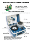
20 Cubic Foot
Aluminum Tank
40 Bar Analog Gauge
Safety Valve
Rate Valve
Compression
Gland
Screw
Pressure Chamber
Lid
Pressure Chamber
Control Valve
Tank Hose Connection
Instrument Specifications:
Portable Tank Valve
Portable Tank Hose
1 of 5 Tie Down Points
Tank Pressure Gauge
Shoulder Strap Connections
Maximum Instrument Operating Pressure: 40 BAR/ 600 PSI
Chambers Construction: Anodized Solid Stock Aluminum
Maximum Portable Tank Pressure: 207 BAR/ 3000 PSI
Weight: 32 Pounds / 14 Kg
1
2
1) A lower canopy,
shaded leaf is
covered with foillaminate bag.
3
2) The water in the
stem is under
tension.
3) The stem is cut
and the leaf with
bag is sealed
inside chamber.
4) Pressure is
applied to the
leaf until water
appears at the
cut surface.
4
How it Works
Simply put, the pressure chamber is just a device for applying pressure to a leaf or small shoot.
Most of the leaf is inside the chamber, but the cut end of the stem (the petiole) is exposed
outside the chamber (see illustration above). The amount of pressure it takes to cause water
to appear at the cut surface of the petiole tells you how much tension the leaf is experiencing
on its water supply. A high value of pressure means a high value of tension and a high degree
of water stress. These stress levels vary within different species. The unit of pressure most
commonly used is Bar (1 Bar = 14.5 PSI).
2
What is Plant Moisture Stress?
The water status of plants, and how to measure it, has received much attention in recent
years and for good reason. Plant moisture stress (PMS), or plant water potential, indicates
the demand for water within a plant. A PMS measurement indicates the water status of a plant
from the “plant’s point of view.” PMS also tells how the environment affects the plant. High
PMS levels cause many physiological processes, such as slowing or stopping photosynthesis.
Conditions producing high PMS reduce plant growth and may eventually result in the death of
the plant. PMS information can be used to evaluate the plants need for water or how well it is
adapted to its environment.
Why Measure Plant Moisture Stress?
Measuring PMS gives an indication of a plants ability to grow and function and can be used as
a guide for managing the plants moisture environment so as to improve growth and crop yield.
Air temperature, wind speed, humidity, and soil moisture are all integrated by the plant into
one single value — PMS. A measure of PMS thus gives an evaluation of the moisture status
of a plant from the plants point of view. It is an excellent tool for aiding in irrigation scheduling
for crop plants such as almond, walnut, prunes, cotton, and wine grapes or for any application
where plant growth is managed such as in nurseries, greenhouses, seedlings or reforestation.
Principle of Operation
The pressure chamber can be thought of as measuring the “blood pressure” of the plant
— except that for plants it is water rather than blood. And the water is not pumped by a heart
using pressure, but rather pulled with a suction force as water evaporates from the leaves.
Water within the plant mainly moves through very small inter-connected cells, collectively
called xylem, which are essentially a network of pipes carrying water from the roots to the
leaves. The water in the xylem is under tension. As the soil dries or humidity, wind or heat load
increases, it becomes increasingly difficult for the roots to keep pace with evaporation from
the leaves. This causes the tension to increase. Under these conditions you could say that the
plant begins to experience “high blood pressure.”
Since tension is measured, negative values are typically reported. An easy way to remember
this is to think of water stress as a “deficit.” The more the stress the more the plant is
experiencing a deficit of water. The scientific name given to this deficit is the “water potential” of the plant. The actual physics of how the water moves from the leaf is more complex than just “squeezing” water out of a leaf, or just bringing water back to where it was when the leaf
was cut. However, in practice, the only important factor is for the operator to recognize when
water just begins to appear at the cut end of the petiole.
The Plant Moisture Stress (PMS) reading at any given time reflects the plant’s interaction
with the water supply and the demand for water placed upon the plant by its environment
(see diagram on back cover). Since these factors are almost always changing, PMS is nearly
always changing. The time of measurement therefore requires careful consideration — PMS
is most at midday and least just before sunrise. Pre-sunrise PMS values will usually reflect
average soil moisture tension, if the soil is uniformly irrigated. Midday PMS values reflect the
tension experienced by the plant as it pulls water from the soil to satisfy the water demand of
the atmosphere.
3
GETTING STARTED
The instrument is complete with a 20 Cubic Foot Portable Nitrogen Tank. The Tank is fitted with a
CGA-580 Nitrogen Valve which is standard for US Nitrogen Service.
Tank is rated for a maximum pressure of 207 Bar/3000 PSI. The tank may be safely filled by using the
“Trans-filling” method described in “Filling the Portable Tank” or having it filled at a Gas Supply Store.
The instrument is designed for use with nitrogen (N2). Welding Grade is sufficient. Maximum pressure
in the Portable Tank or any tank connected to the instrument should not exceed 207 Bar/3000 PSI.
If the tank has not yet been filled, consult the tutorial on filling the tank.
USING THE PRESSURE CHAMBER
1. Turn the Control Valve to the “OFF” position.
2. Slowly open the valve on the Portable Tank. One-half to one turn is normally sufficient. Pressure
will register in the Tank Pressure gauge. If tank is empty refer to Filling Portable Tank tutorial.
3. Check the Safety Valve and set the Rate Valve using the following procedure.
4. Remove the lid from the chamber by turning
the lid counter-clockwise and lifting. Place a solid
rubber stopper inside the recessed area under the
lid as shown. Put the lid back on the chamber by
pushing down and turning clock-wise to the stop.
Lid must be turned completely to the stop to close
the brass Safety Valve. If the stainless steel piston
is not depressed, chamber will not pressurize. This
is a safety feature of the instrument to ensure lid is
properly seated.
Turn Control Valve to CHAMBER position and pressurize the chamber. Adjust Rate Valve until
pressure in the chamber increases at the desired rate. ½ Bar per second is a recommended rate of
increase. Rate may be changed at any time, even while pressurizing a sample.
CAUTION
Do not close Rate Valve completely or use as a Shut-Off Valve.
Valve may be damaged as a result.
5. Turn the Control Valve to EXHAUST position to release pressure from the chamber. Remove the
lid and solid rubber stopper from the inside of lid. You are now ready to take readings.
4
6. You can now select a leaf to test. To seal the sample, insert the cut end of the petiole (stem)
through the hole from the bottom side of the chamber lid. Twist the Compression Screw clockwise
to seal the sample in the lid. For more detailed information about sampling – consult our website.
WHEN YOU HAVE COMPLETED MEASUREMENTS
1. Close the Valve on the Portable Tank.
FILLING THE PORTABLE TANK
In order to successfully fill the Portable Tank,
the following items are needed:
1. 6-Foot Filling Hose.
2. Nurse Tank (Large Tank).
3. Model 615 Pressure Chamber.
5
1. Ensure the Portable Tank Valve is closed. Check the Tank Pressure Gauge to ensure
it reads zero and that there is no pressure in
the instrument or Tank Hose. If there is still
pressure, remove the lid of the instrument
and cycle the Control Valve to Chamber
position.
2. Detach the Tank Hose by releasing the
quick coupler. 3. Connect the end of the 6-Foot Filling
Hose to the Tank Hose.
4. Connect the other end of the 6-Foot Filling
Hose to a Nurse Tank that has 207 Bar/3000
PSI or less pressure in it.
5. Ensure that the Control Valve is in the
“OFF” position.
6
6. Ensure that the Nurse Tank Valve is
completely closed.
7. Ensure that the Purge Valve on the 6-Foot
Filling Hose is completely closed.
8. Ensure that the Portable Tank Valve is
completely closed.
7
9. The system should now look like this.
10. Next, open the valve on the Nurse Tank
slowly.
This allows pressure down to the Portable Tank
and you can verify quantity of pressure in Nurse
Tank by looking at the 6-Foot Filling Hose
gauge..
8
11. Next, open the Portable Tank Valve
— just barely. 1/6 of a turn at first and
you will hear the gas begin to enter
the tank. Wait for the gas to equalize
— you will be able to hear the gas enter
the tank. When the noise stops, simply
open the Portable Tank Valve a little
more. Eventually you will have the valve
completely open. The whole process
should take about 4-5 minutes.
CAUTION
Ensure you fill the tank slowly.
Filling it too quickly will cause the valve to heat up and can cause damage to the valve.
12. Now the tank is full, close the Portable Tank Valve. Close the Nurse Tank Valve.
13. Open the Purge Valve on the 6-Foot Filling Hose to release the pressure from the hose.
14. Reconnect the Portable Tank Hose to the Tank Hose Connection and give it a tug to ensure
properly connected.
9
Testing the Safety Valve
The instrument is fitted with a Safety Valve
to ensure that the lid is properly seated prior
to pressurizing the chamber. The Safety Valve
will vent the chamber if the lid is not properly
closed. This valve MUST be tested at the
beginning of each measurement session.
1
2
First, use your finger to depress the piston
so that it is inside the safety valve
Insert a solid rubber gasket into the lid
4
3
Turn the lid
clockwise to
the stop.
Ensure the
cam is directly
over the
piston
Install the lid on the chamber
10
6
5
Then turn
the lid back
so that the
cam
is not
blocking the
piston
Begin to slowly apply pressure to the chamber
7
safety valve
Nut
Collar
The safety
valve should
pop open
before the
pressure
reaches
2 bar
Piston
Buna 70 O-Ring (006)
Elbow
You will hear nitrogen escaping from the valve and the pressure will not increase in the chamber.
If it does not, turn the control to EXHAUST, then remove the nut and piston of the safety valve and
lubricate the O-ring on the piston with petroleum jelly. Reassemble and test the safety valve again. When the safety valve opens, the pressure in the chamber should drop to near zero. This time the
safety valve should open at a pressure below 2 bar. If it does not, remove the nut and piston of the
safety valve and again clean and lubricate the O-ring on the piston with petroleum jelly. Check for
any foreign debris then reassemble and test the safety valve again.
The safety valve is an important safety component of the instrument. Do not attempt to operate
the instrument until the safety valve is operating properly; that is, until it is releasing the chamber
pressure at less than 2 bar pressure,
As an added safety precaution, the cover should be left in only one of two positions:
1. On the chamber and completely locked in place; or
2. Completely removed from the chamber.
The lid should never be left in any intermediate position.
11
INSTRUMENT MAINTENANCE
1) Remove the O-Ring from around the lid. Clean with rag and
lubricate with Petroleum Jelly for optimal performance.
2) Remove the Compression Gland Screw from the lid. Clean the threads of the Screw and the Compression Gland Base with a rag. Lubricate this with Lithium Grease (White Grease) for optimal performance.
3) Compression Gland Gasket can be cleaned with a rubber treatment such as used with automobile detailing (Armour All
brand) for optimal performance. When Compression Gland Gasket
becomes worn – replace with new gasket for optimal performance.
CONTROL VALVE ADJUSTMENT
The control valve will need periodic adjustment
depending upon usage. Adjustment is required
if leakage occurs in the pressurized instrument
with the control valve in the OFF position. Two
tools are needed and have been provided with
your instrument. A 3/32 inch Allen Key is used to
remove the Control Valve Handle. A 11/32 inch
wrench is used to adjust the packing on the valve.
1. Pressurize the instrument with the control valve
in the OFF position.
2. Loosen the hex screw with the Allen Key. It is
located on the side of the Control Valve Handle.
3. Using the 11/32 wrench, slowly tighten the
packing gland nut until the leak stops.
CAUTION
Do not overtighten the packing gland!
Permanent damage to the valve will result.
4. Replace the handle and tighten the hex screw.
For a complete list of picture tutorials and videos - www.pmsinstrument.com
12
Maintenance for Compression Gland Lid
Maintaining the Compression Gland Lid is quite simple. Keep the O-ring around the
Compression Gland Insert clean and lubricated with petroleum jelly. Occasionally unscrew the
compression screw and take out the Compression Gland Insert and Compression Gland Gasket
inside for cleaning. We recommend lubricating the compression screw threads with a Lithium based lubricant such as white grease or other lubricant to maintain the threads and ensure easy
operation. Keeping these threads clean is important for ensuring operability of the cover. Clean the Compression Gland Gasket with ARMOR ALL or other similar cleaner. Over time the
compression gland gasket will become worn, a replacement has been supplied for your convenience. If additional gaskets are needed, you may purchase them directly from PMS Instrument Company.
Compression Gland Screw
Chamber lid
Friction washer
(Red)
4 Buna 70 O-Rings (006)
Compression Gland Insert
Compression Gland Gasket
Compression Gland Base
1 Buna 70 O-Ring (330)
4 Brass Screws
To re-assemble the Compression Gland start by:
1. Sliding the Compression Gland into the Chamber Lid
2. Insert the 4 brass screws and screw the insert down tight — make sure that the 4 small O-rings are in place first
3. Put the Compression Gland Gasket into the Compression Gland Base
4. Put the Compression Gland Insert on top of the gasket and the Friction Washer on top of the Compression Gland Insert
5. Be sure to lubricate the threads and screw the Compression Screw into the Compression
Gland Base
6. The Compression Gland Cover is now ready for use
13
Warnings, Considerations and Limits
Intended Usage
The Pressure Chamber Instrument usage is intended for applying pressure to plant material to
determine water potential or to extract water xylem from plants. It should not be used to pressurize
anything other than plant material. Using this instrument for any other purpose or in an unsafe manner could result in harm to the user.
Upon receiving the instrument or using it for the first time, each user should familiarize themselves
thoroughly with all safety features and set-up process to avoid damage of instrument or physical injury to operator.
Working Environment
The instrument is robust and durable and designed for outdoor use. It may be used in temperatures
as high as 55º C and as low as –10º C. It is best to store inside where temperatures do not exceed
40º C or lower than 0º C. Keep in clean and dry area. Store on a flat surface that is protected from
being struck or damaged. Normal vibration during use will not affect performance of the instrument
such as travel in vehicle or all terrain vehicles. Excessive shaking and vibration can cause damage. If the instrument has received a hard blow or hit, it should be evaluated prior to further use. The
instrument is not vulnerable to humidity but should never be submersed in water. If the instrument
becomes submersed, allow it to dry and evaluate the instrument prior to further use.
Transporting Instrument
Transporting the instrument by any mode should be done with care as not to strike the instrument
against anything hard as this might damage the instrument. If transporting by vehicle such as truck,
car or all terrain vehicle; the instrument should be securely fastened in order to avoid any damage to
the instrument.
Maintenance
Most maintenance issues can be done without much training. Consult the maintenance pages in this
manual. However, any adjustments to piping or high pressure connectors should only be performed by factory or authorized personnel. Consult us directly for more information.
Disposal or Decommission of the Instrument
While the instrument should provide years of use, it is possible that sometime it will be disposed of. Local recycling guidelines should be followed for disposal.
14
PMS Instrument Company
1725 Geary Street SE ✦ Albany OR 97322
Phone: (541) 704-2299
FAX: (541) 704-2388
E-mail: [email protected]
www.pmsinstrument.com
EU
Declaration of Conformity
We,
PMS Instrument Company
1725 Geary Street SE
Albany, OR 97322 USA
Declare under our sole responsibility that the following products:
Pump-Up Chamber, 600 Pressure Chamber, 605 Pressure Chamber, 615 Pressure Chamber,
615D Pressure Chamber, 1000 Pressure Chamber, 1005 Pressure Chamber, 1000
“upgraded to 100 Bar” Pressure Chamber, 1005 “upgraded to 100 Bar” Pressure Chamber.
In addition, the following accessories are included:
Cavitation Chamber
To which this declaration relates is in conformity with the following Standards or other normative
documents:
EN ISO 12100-1:2003, EN ISO 12100-2:2003, 97/37/EC Annex I
Following the provisions of Directives;
98/37/EC, 97/37/EC (Equipment is below class I limits per the PED)
Responsible party in the European Union:
Place: Elancourt, France
Date: May 6, 2009
President, PMS Instrument Company:
Place: Albany, Oregon, USA
Date: May 6, 2009
15
Atmospheric Demands: The atmosphere of the plant puts four different demands on the
plant: wind, humidity, air temperature, and radiation.
Plant Regulation: The plant regulates water stress by opening and closing the stomata
(small holes) on the backside of the leaf. Other regulators used are leaf flagging, rolling and
leaf loss. Good root development is also key in regulating water stress.
Soil Supply: Soil composition is critical for the plant. Moisture content is a key factor in PMS.
In addition, the temperature of the soil and depth will influence PMS. Depending upon the
texture of the soil and how it holds moisture is another important aspect of the soil. Loose
sandy soil will drain out moisture quickly while heavy clay will hold moisture longer.