1
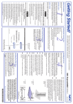
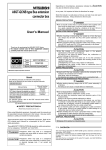
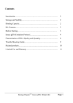
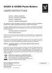
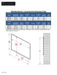
Operating Instructions
EziTite IBS Hydraulic Nut
Technofast Industries Pty Limited
667 Boundary Rd
Richlands Qld 4077
Ph: (07) 3375 1431
Fax: (07) 3375 9094
EziTite IBS Hydraulic Nut
Fitting Instructions
1
6
4
2
5
9
8
3
7
EziTite Hydraulic Nut
Components
1. Nut Body: screws onto the boom rope thread.
2. Piston: contains hydraulic pressure and seals.
3. Spherical Washer: designed to self-correct seating and misaligned bolts, also works
as a bridge to allow the locknut to be wound down.
4. Lock-Ring: to retain the load when hydraulic pressure is released.
5. High Pressure Seals: Seals.
6. SHCS: Used to deform the thread of the lockring to stop from releasing load when
dragline is in operation.
7. Locknut: used to hold tension whilst the hydranut is returned to the home position
8. High Pressure Inlet: 1/8” BSPP port with male hydraulic nipple.
9. C Spanner/Tommy Bar Hole: to nip up lock ring.
YOUR EziTite HYDRAULIC NUT COMES ASSEMBLED AND READY FOR FITTING
EziTite IBS Hydraulic Nut Operation Manual
Revision 2 May 2011
Page 2 of 13
Safety
Before attempting installation of EziTite Hydraulic Nuts it is imperative operators
understand the installation and tensioning procedures contained in this manual.
DO NOT ALLOW UNTRAINED STAFF ATTEMPT INSTALLATION!!
DO NOT allow personnel into the installation area without firstly instructing them on the
safety hazards of hydraulic components.
PRE-INSTALLATION SAFETY CHECKLIST.
1. Are all persons in the installation area aware of safety procedures contained in
this manual?
2. Have all persons in the installation area been issued with adequate eye and
hearing protection devices?
3. Have all persons in the installation area been issued with suitable protective
clothing?
4. Are installation personnel trained in the dangers of misuse of high-pressure
hydraulic equipment?
5. Is the installation area free of unnecessary obstructions, which could endanger
personnel, performing their assigned tasks?
6. No person should be allowed in close proximity to hydraulic components while
pressurising the system.
7. When pressurising the system the pump operator must remain at their station, at
the pressurising pump, in case of emergency.
8. Set air regulator to achieve the correct oil pressure for the product before
coupling and tensioning begins.
REMEMBER!
Fluids under high pressure can cause damage or injury if the device is improperly
used.
Incorrect installation procedures can lead to major safety problems & void warranty.
EziTite IBS Hydraulic Nut Operation Manual
Revision 2 May 2011
Page 3 of 13
Fitting EziTite IBS Hydraulic Nut
1. The “EziTite IBS Hydraulic Nut” is supplied with a Locknut (item 7). It should be
wound into position on the bolt with the large chamfer side facing the outwards.
Lock Nut
(item 7)
2. Place the Spherical Washer (item 3) over the stud and nut.
Spherical
Washer
(item 3)
EziTite IBS Hydraulic Nut Operation Manual
Revision 2 May 2011
Page 4 of 13
3. Using the machined hex on the top of the EziTite IBS Hydraulic Nut assembly
wind the assembly onto the stud until it is engaged with the spherical washer.
4. Nip up the assembly with a spanner to take up any slack from the joint.
5. Connect the pressure pumping apparatus hose to the hydraulic male coupler
provided. To ensure the EziTite Hydraulic Nut has a full working stroke open the
pressure relief port of the pump when connected. The Screw action downwards will
easily reset the stroke of the EziTite IBS Hydraulic Nut.
EziTite IBS Hydraulic Nut Operation Manual
Revision 2 May 2011
Page 5 of 13
6. Ensure that the lock ring remains free from the piston.
7. Close the pressure relief port.
The EziTite IBS Hydraulic Nut is now ready for tensioning!!
Tensioning EziTite hydraulic nut
8. Operate the pumping apparatus and slowly charge the EziTite Hydraulic Nut to
requied pressure (refer to load pressure graph suplied with EziTite Hydraulic Nut and
the dragline manufacturers specifications).
Do not advance the Nut Body too far out of the Piston or seal damage will occur.
Maximum Stroke is 30mm.
OIL
FLOW
EziTite IBS Hydraulic Nut Operation Manual
Revision 2 May 2011
Page 6 of 13
10.Due the limited amount of stroke which the EziTite Hydraulic Nut has you may be
required to screw the locknut down and return the EziTite Hydraulic Nuts to their home
home position (as below)
EziTite at full
stroke
Locknut wound
home to hold
load
EziTite in
homeposition
EziTite IBS Hydraulic Nut Operation Manual
Revision 2 May 2011
Page 7 of 13
10.Keep Repeating steps 9 & 10 until the boom rope it tensioned to the required level.
11.Once the required load is reached screw the lockring down so it is touching the face
of the piston. If the lockring is not contacting the face evenly repeat steps 9 & 10 as this is
because the piston is misaligned. Once alignment is correct nip up the lockring. Do not over
tighten the lockring as this will make removal difficult.
12. To prevent the EziTite IBS Tensioner from moving when the dragline is in operation
the locknut is to be locked onto the base off the EziTite. To do this wind the Locknut up to
the base of the EziTite so that it contacts the Bridge. Now pressurise the EziTite to 200 bar
and wind the lockring down so that it contacts the piston as in the previous step.
Tensioned
EziTite
Pressurised EziTitewith
locknut hitting
underside of bridge
Lockring wound
home locking the
assembly in place
12.Tighten the SHCS (item 6). This will deform the thread on the lockring to ensure that it
does not become loose during operation.
13. Your EziTite IBS Hydraulic Nut is now ready for service.
EziTite IBS Hydraulic Nut Operation Manual
Revision 2 May 2011
Page 8 of 13
IMPORTANT
1. Ensure that the base or washer face of the EziTite Hydraulic Nut contacts the joint face
evenly and is fully supported across its full diameter.
2. DO NOT EXCEED indicated pressure or working stroke as damage to equipment may
occur.
3. The Lock-Ring must contact the abutting face of the Piston evenly when tightened. If
not, repeat the tensioning procedure. DO NOT over tighten Lock-Ring with excessive
force, only nip tight.
Removal
To remove the EziTite IBS Hydraulic Nut from service, a procedure much the reverse of
that for tensioning, is carried out.
1. Couple the Pressure pumping apparatus to the EziTite IBS Hydraulic Nut.
2. Charge the EziTite IBS Hydraulic Nut to approximately 300 bar or until the Lockring
loosens.
3. Unscrew the Lock-Ring sufficiently to allow the bolt/stud to return to its un-tensioned
length when Hydraulic pressure is released this will also allow the Locknut to release
from the underside of the Bridge.
4. Relieve the pressure in the Pumping apparatus and in the EziTite IBS Hydraulic Nut.
5. Whilst the Hydraulic hoses are still connected the EziTite Hydraulic Nuts, the piston
should be returned to a closed position by inserting the pin spanner and winding it in
a clockwise direction to push the piston home.
6. Disconnect Hydraulic hose and fit protective covers to hose and fittings.
7. Unscrew the EziTite IBS Hydraulic Nut from the bolt.
EziTite IBS Hydraulic Nut Operation Manual
Revision 2 May 2011
Page 9 of 13
SEAL REPLACEMENT
Before seals are replaced the EziTite IBS Hydraulic Nut must be disassembled. Remove
the EziTite Hydraulic Nut from operation and follow these instructions:
1. Attached an air supply to the male coupler and blow air into the EziTite Hydraulic Nut to
separate the Nut Body from the Piston. Note: Do not use excessive pressure or
sudden burst of air as this may cause the piston to fly off with excessive force.
2. Remove old or damaged seals and clean all parts.
3. Inspect the internal seal contact surfaces and repair where necessary. That is, polish off
burrs and pick-up marks.
4. Lightly oil the two surfaces.
5. Place the ID O-ring over the spigot end of the Nut Body.
6. Place the OD O-ring inside the Piston at the bottom of the seal surface.
Inner Seal
Outer Seal
7. Carefully place the Nut Body inside the piston and push together.
8. Inspect the nipple for wear or damage and replace if needed. NOTE: The nipple is to
be tensioned to 50Nm.
9. Screw the assembly onto a test stud with an appropriate thread size, with the spherical
washer in place. Tighten only lightly against the seals. Note: if a test stud is
unavailable this can be done on the studs being tensioned.
10. Apply a quick charge of hydraulic pressure of between 1000 to 1500 psi to set the
internal seals into place.
11. Relieve the internal pressure.
Screw the EziTite IBS Hydraulic Nut to fully closed position. This should
be easy to do. If not the seals may be trapped. Therefore repeat all of the
procedure.
EziTite IBS Hydraulic Nut Operation Manual
Revision 2 May 2011
Page 10 of 13
EziTite Hydraulic Nut Maintenance And Repair
If the EziTite IBS Hydraulic Nut should be damaged in service, for example by overheating,
which may destroy the unit’s seals, it may be removed as a last resort by carefully splitting
the Lock-Ring. When the Lock-ring is removed, the piston will retract normally. If the outer
thread of the Nut Body has not been damaged during removal, new seals and lock-ring
can normally be fitted and the unit returned to service.
In most applications EziTite Hydraulic Nuts are unlikely to require any further care other
than to ensure that they remain free from rust and deposits, which could affect the
operation of, machined threads.
Replacement parts are available by request.
EziTite IBS Hydraulic Nut Operation Manual
Revision 2 May 2011
Page 11 of 13
Limited Warranty
Technofast manufactured products are warranted free of original defects in material and workmanship for a
period of one year from the date of shipment to the first user. This warranty does not include seals nor failures
caused by lack of proper maintenance; in-compatible fluids; foreign materials in the driving media; in the
pumped media; or application of pressures beyond specified ratings. Products believed to be originally
defective may be returned, freight prepaid, for the repair and/or replacement to the distributor, authorised
service representative, or to the factory. If upon inspection by the factory or authorised service personnel, the
problem is found to be originally defective material or workmanship, repair or replacement will be made at no
charge for labour or materials. F.O.B. the point of repair or replacement. Any claim for Warranty must be
addressed to Technofast, which shall at its’ discretion issue an Authority to Return in respect of such goods.
This Authority must be received before return shipment and include the following: the original purchase date,
purchase order number, model number and other pertinent data to establish a warranty claim, and to expedite
the return or replacement to the owner.
Any such warranty is void if;
the product has been disassembled and reassembled in a facility other than Technofast or a facility suitably
and currently qualified by Technofast in conformance with its Quality Standards,
or
substitute parts have been used at any time in place of factory manufactured parts
or
the product has been used in any manner not in accordance with the manufacturer’s directions.
or,
where any modifications not qualified by Technofast in writing have been made to the product
Any modifications to any Technofast product made by any party other than those suitably qualified by
Technofast shall be the sole risk and responsibility of that party. Technofast disclaims any and all liability,
obligation, or responsibility for the modified product; and for any claims, demands, or causes of action for
damage or for personal injuries resulting from the modification and / or use of such a modified Technofast
Product.
TECHNOFAST’S OBLIGATION WITH RESPECT TO ITS PRODUCTS SHALL BE LIMITED
TO REPLACEMENT, AND IN NO EVENT SHALL TECHNOFAST BE LIABLE FOR ANY
LOSS OR DAMAGE, CONSEQUENTIAL OR SPECIAL, OF WHATEVER KIND OR
NATURE, OR ANY OTHER EXPENSE WHICH MAY ARISE IN CONNECTION WITH OR
AS A RESULT OF SUCH PRODUCTS OR THE USE OR INCORPORATION THEREOF IN
A JOB. THIS WARRANTY IS EXPRESSLY MADE IN LIEU OF ALL OTHER
WARRANTIES OF MERCHANTABILITY AND FITNESS FOR A PARTICULAR PURPOSE.
NO EXPRESS WARRANTIES AND NO IMPLIED WARRANTIES WHETHER OF
MERCHANT ABILITY OR FITNESS FOR A PARTICULAR PURPOSE OR OTHERWISE,
OTHER THAN THOSE EXPRESSLY SET FORTH ABOVE, SHALL APPLY TO
TECHNOFAST PRODUCTS.
EziTite IBS Hydraulic Nut Operation Manual
Revision 2 May 2011
Page 12 of 13
Points To Note
The EziTite IBS Hydraulic Nut and all related intellectual property disclosed herewith is
covered by Australian and International Patents.
Due to the nature of applications of these fasteners, the manufacturer can accept no
responsibility for their performance.
For Technical Advice, please contact your nearest TechnoFast agent
or contact Technofast directly.
Technofast Industries Pty Ltd
667 Boundary Rd
Richlands Qld 4077
Brisbane, Australia
Telephone:
Facsimile:
Web site:
61 7 3375 1431
61 7 3375 9094
www.technofast.com
EziTite IBS Hydraulic Nut Operation Manual
Revision 2 May 2011
Page 13 of 13