Transcript
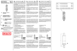
Penalty
Penalty Mode
Disconnect level
15
Discharge
Load Reconnect
13
12
Load Connect
# Sundaya
Penalty
PWM Float Charge
Charge
14
Load Reconnect
Buzzer
Buzzer
11
Penalty Load
Voltage
Boost
Load Reconnect
Level
Operation:
Load Disconnect
& Penalty ON
Load Disconnect
Level
Remarks :
Load
Load Connect Area
Penalty
Buzzer Warning
Penalty Area
STAGE - 1
STAGE - 2
STAGE - 3
STAGE - 4
STAGE - 5
STAGE - 6
STAGE - 7
STAGE - 8
STAGE - 9
Stage-1: - When the Controller is first connected to a half charged
battery (SOC < 12.7V).
Penalty mode LED Indicator - on
Load cut-off
Stage-2: - After the battery is charged up to SOC > 12.7V.
Load indicator on
Stage-3: - After the battery fully charged (SOC > 14.5V)
Penalty mode LED Indicator - off
Controller entry to PWM mode to prevent the battery being
over charged
The Charging LED indicator will start to blink
Stage-4: - The battery discharged to SOC < 11.7V.
Warning buzzer on
Stage-5: - The battery continues discharge to SOC < 11.5V.
Deep discharge Cut-Off LED Indicator on
Penalty mode LED Indicator on
Load cut-off
Stage-6: - The battery recharged back to SOC > 12.7V
Deep discharge Cut-Off LED Indicator off
Load indicator on
Stage-7: - Under the Penalty mode, the battery discharged to SOC <
12.1V.
Warning buzzer on
Stage-8: - Under the Penalty mode, the battery continues to be
discharged to SOC < 11.9V Load cut-off
Stage-9: - The battery charged back to SOC > 12.7V
Load indicator on
After the battery fully charge (SOC > 14.5V)
Penalty mode LED Indicator - off
Controller entry PWM mode to prevent over charge
Safety:
# User should ensure the surface for mounting the controller is
sufficiently strong to carry the weight of the unit.
# Short circuit of batteries could generate excessive heat and possibly
melt down the cables, causing injury to the User. During installation or
battery replacement it is advisable to connect and secure the battery
cable to the controller first, before connecting to the terminals on the
battery.
Warning:
# Do not connect the controller to AC power.
# Although all controllers are reverse polarity protected, User should
ensure correct connection by respecting the polerities.
# All controllers are designed for indoor uses only.
# All solar panel or charger connected to the controller should be
dedicated to 12Vdc applications, and the current suplied to the controller
should be equal to or smaller than the controller's output current. For
example: Apple-5 - The maximum current input from solar panel or charger
should NOT excess 5A.
Apple-10 - The maximum current input from solar panel or charger
should NOT excess 10A.
Apple-15 - The maximum current input from solar panel or charger
should NOT excess 15A.
Warranty:
All Sundaya Controller are warranted for any defects caused by faulty
components or factory error. Warranty period varies depending on the
country. Please check with your local dealer for details.
The warranty will be void under the following conditions:
-The Product shows signs of having been exposed to water spill or
submerged in liquid.
-The Product shows signs of being opened, or warranty seal is broken.
-The Product shows signs of abuse or misuse.
Mechanical Specification:
Enclosure Materials : ABS
Color
: Green
Shape
: Round
Size
: 120mm x 40mm
Terminals
:
# 8mm width Input terminal for Battery (bottom side)
# 8mm width Input terminal for Solar Panel (top side)
# 8mm width Output terminal for Load (top side)
Electrical Specification:
Nominal operating Voltage
Self consumption
Current Model Apple 5
Current Model Apple 10
Current Model Apple 15
Low Voltage Buzzer Warning Level
Low Voltage disconnect
(Non-Penalty mode)
: 12VDC
: 4 mA
: 5 Amp -0% +25%
: 10 Amp -0% +25%
: 15 Amp -0% +25%
: 11.70 V (Non-Penalty mode)
: 11.50 V +/- 0.10 V (Non- Penalty mode)
(with discharge current
compensation -0.04V/A)
Low Voltage Buzzer Warning Level : 12.10 V (Penalty mode)
Low Voltage disconnect
(Penalty mode)
Load Reconnect level
Penalty mode reset
Boost Charge Level @250c
PWM float Charge level
: 11.90V +/- 0.10V (Penalty mode)
(with discharge current
compensation -0.04V/A)
: 12.70 V
: 14.50V +/- 0.10V
: 14.5V (with Temperature
compensation -0.02V/deg C)
: 14.10V (with Temperature
compensation -0.02V/ deg C)
Apple
User's Manual
Product Description
The "Apple" is a unique small PV charge/discharge controller in the
Sundaya product range, specially designed for cost-effective applications
based on SMD technology. The Apple is extremely power- efficient due to
its very low voltage drop over both input and output switching Mosfets.
Unique features include Forced Health Improvement (FHI®) algorithm,
and a buzzer to remind the User of the battery’s SOC (State of Charge) as
it gets close to LVD (Low Voltage Disconnect). Furthermore, it comes with
a self-reset electronic master-switch, so that whenever the Apple is
reconnected to the battery or simply newly installed, the output will
always stay inactive until the user presses on the reset switch. A SOC
(State of Charge) indicator gives clear indication of the battery's status.
Forced Health Improvement (FHI®):
Frequent cycling of the battery at a very low state of charge causes
fast deterioration of the battery due to sulphation and stratification.
The Apple will not allow the User to frequently operate the battery at
low state of charge. After reaching a forced Low Voltage Disconnect
(LVD), the user will not be able to discharge the battery to the same
low level again next day. This is indicated to the user with a yellow LED
Penalty mode. Only after reaching the Boost Charge level of 14.5V the
Penalty mode will be reset and the Apple will allow the user to use the
full battery capacity again.
The Apple is available in 3 standard charge/discharge current
capacities 5, 10 and 15 Amperes. With its clean and round appearance,
and all cable connections nicely covered at the backside of the unit,
the Apple is esthetically attractive for indoor installation.
Main Features:
# Strong input and output connectors with clear polarity markings
# Cable connectors not reachable and not visible after mounting on the
wall (safety and esthetic reasons)
# Extremely low voltage drop over power mosfets
# Boost Charge mode
# LED Indicator for charging
# LED Indicator for state of charge in 8 steps
# Electronic Overload/Short circuit protection with LED Indicator
# Electronic Master-switch to centrally cut off all loads
# Deep discharge cut off with LED Indicator
# Forced Health Improvement (FHI®) feature
# Sundaya
7
1
2
6
5
3
4
1
LED Indicators and Button/Switch Description:
1 8-steps SOC (State of Charge) LED Indicator
To indicate the SOC of the batteries, the SOC level is proportional to the
numbers of the LEDs lit up. Example: All 8 LEDs lit up indicate the
batteries are fully charged (SOC = 12.7 - 13.1V); Only the first (lowest)
LEDs lit up indicate the batteries close to exhaustion, the output of the
controller will soon be cut if the LOAD continues to be connected
without sufficient charging to replenish the batteries (SOC = 11.4 11.7V).
2. Deep discharge Cut-Off LED Indicator
To indicate that the controller disconnected the output due to SOC
falling below 11.9 V +/- 0.10 V on Penalty mode, or 11.5V +/- 0.10 V on
Non Penalty mode.
3. Display Button
The 8-steps SOC (State of Charge) LED Indicator, Deep discharge Cut-Off
LED Indicator, Master-switch / Overload/Short circuit LED Indicator, and
Penalty mode LED Indicator will display the status only when the Display
Button pressed.
4. On/Off Master-Switch
Toggle the controller output from on to off, or off to on by pressing the
switch once.
5. Master-switch / Overload/Short circuit LED Indicator
The LED Indicator will light up when the User turns off the output by
pressing the On/Off Master-Switch once, or the controller cuts off the
output due to a short circuit detected.
6. Penalty mode LED Indicator
The LED Indicator will light up when the Penalty mode is in effect, due to:
- During controller’s first power up, the SOC of the battery is below 12.7V
- After the controller disconnected the output due to SOC falling below
11.9 V +/- 0.10 V on Penalty mode, or 11.5V +/- 0.10 V on Non Penalty
mode.
7. Charging LED Indicator
The LED Indicator will light up when charging take place.
Load Terminal
Connector
PV Terminal
Connector
Battery Terminal
Connector
# Sundaya
Sundaya Contact Information
Sundaya International Pte., Ltd.
Address
: II Tampines street 92
SINGAPORE 528872
E-mail
Web Site
Telephone
Facsimile
:
:
:
:
[email protected]
www.sundaya.com
+65 6788 8345
+65 6788 8749
Sundaya Indonesia, PT.
Address
: Jl. Pondok Randu No.38
Cengkareng, Jakarta Barat
INDONESIA 11750
Telephone
: +62 21 541 6103-05
Facsimile
: +62 21 541 6106
# Sundaya
Installation procedure:
1. Unpack the controller.
2. Prepare a fully charged battery.
3. Connect the controller to the fully charged battery. (Caution: - please
make sure the polarities are correctly connected)
4. Press on the Display Button. All the 8-steps SOC (State of Charge) LED
Indicator should light up if the battery is fully charged.
5. Connect the controller output to the load. Ideally, use low power load
first such as DC lighting product (Ulite3), to verify proper operation.
(Caution: - please make sure the positive and negative polarities are
correctly connected)
6. Press the On/Off Master-Switch, and hold for one or two seconds, then
release. The Load will turn on.
7. Connect the Solar Panel Input to either 12Vdc Solar modular or 12Vdc
charger such as DC10. (Caution: - please make sure the positive and
negative polarities are correctly connected)
8. The Charging LED Indicator should light up if charging is taking place.
9. Mount the controller in indoor environment with minimum exposure
to rainwater, water spill or hot temperature such as cooking oven.
10. The surface to mount the controller should be of good isolated
material such as brick wall, plastic, or wood.
# Sundaya